PERFORMANCE
OF
A
REAL-TIME
SENSOR
AND
PROCESSING
SYSTEM
ON
A
HELICOPTER
F. Kurz, D. Rosenbaum, O. Meynberg, G. Mattyus, P. Reinartz
DLR, German Aerospace Center, 82234 Wessling, Germany -
(franz.kurz, Dominik.rosenbaum, oliver.meynberg, gellert.mattyus, peter.reinartz)@dlr.de
ICWG I/Va
KEY WORDS: real-time processing, sensor design, aerial camera, hazards
ABSTRACT:
A new optical real-time sensor system (4k system) on a helicopter is now ready to use for applications during disasters, mass events and traffic monitoring scenarios. The sensor was developed light-weighted, small with relatively cheap components in a pylon mounted sideward on a helicopter. The sensor architecture is finally a compromise between the required functionality, the development costs, the weight and the sensor size. Aboard processors are integrated in the 4k sensor system for orthophoto generation, for automatic traffic parameter extraction and for data downlinks. It is planned to add real-time processors for person detection and tracking, for DSM generation and for water detection. Equipped with the newest and most powerful off-the-shelf cameras available, a wide variety of viewing configurations with a frame rate of up to 12Hz for the different applications is possible. Based on three cameras with 50mm lenses which are looking in different directions, a maximal FOV of 104° is reachable; with 100mm lenses a ground sampling distance of 3.5cm is possible at a flight height of 500m above ground.
In this paper, we present the first data sets and describe the technical components of the sensor. The effect of vibrations of the helicopter on the GNSS/IMU accuracy and on the 4k video quality is analysed. It can be shown, that if the helicopter hoovers the rolling shutter effect affects the 4k video quality drastically. The GNSS/IMU error is higher than the specified limit, which is mainly caused by the vibrations on the helicopter and the insufficient vibrational absorbers on the sensor board.
1. INTRODUCTION
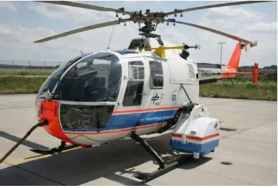
Helicopters are a valuable mean of transportation for security authorities and organisations (Gstaiger 2014). Although, sensors customized for the needs of the BOS and rescue forces exist, e.g. from FLIR, wide-area and real-time mapping sensors are not in use yet. The German Aerospace Center (DLR) makes now the first step towards a real-time mapping sensor by developing the first prototype of the so called 4k system with a certificate of airworthiness for DLR’s BO105 helicopter. The name of the sensor is derived from the 4k video capability and is also a reference to the DLR 3K and the 3K+ camera system (Kurz 2012). Figure 1 shows the 4k system mounted on the BO-105 using an external cargo carrier weapon carrier mount as link between 4k system and helicopter fuselage.
In this paper, the system components, the technical and geometrical sensor properties are presented and discussed with special focus on the influence of the vibrations on the GNSS/IMU accuracies and on the quality of the 4k video stream.
2. THE 4K SYSTEM
The 4k system is designed weight-optimized, small, and relatively low-cost, but equipped with a full real-time image processing chain including a high-capacity data downlink to the ground station. Figure 2 shows the composition of the 4k system, which consists of three non-metric off-the-shelf cameras, a microwave datalink system including two antennas, three processing units and a GNSS/IMU system. Table 1 lists the properties of the most important system components. The 4k system is certified for the BO105 helicopter and mounted on an external cargo carrier on the right side 10cm above the helicopter skids. The platform and housing of the 4k system is decoupled from the helicopter vibrations by using four absorbers inside the system housing. These absorbers mainly
decouple from the vibrations caused by the main rotor and the four rotor blades (7Hz, 28Hz). Additionally, the eigen frequency of the sensor structure should be far away from the main and spurious oscillations of the rotor to prevent damages to the system.
Figure 1. 4k system mounted on the helicopter BO-105
Figure 2. System components of the 4k system
The system is connected to the 28V/35A power supply of the helicopter and to the GPS antenna near the tail rotor. The system can be commanded from inside the helicopter via LAN or from the ground station via data link.
Three optical non-metric cameras are integrated in the sensor with different looking directions (see Figure 3). The latest camera generation from Canon EOS, two 1D-X and one 1D-C, are installed on the platform, which each is capable of acquiring 17.9 MPix images with a frame rate of up to 14Hz.
Additionally, the Canon EOS 1D-C is capable of acquiring 4k movies with a resolution of 4096 x 2160 pixels at 24 fps and is installed in nadir direction. Table 2 lists the properties of the integrated Canon cameras.
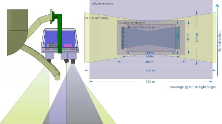
Alternatively, four different lenses from Zeiss with 25mm, 35mm, 50mm and 100mm focal length can be deployed, which leads to different ground sampling distances (GSD) and different footprint sizes on the ground. In Figure 4, the footprints of the most common camera and viewing configurations are visualized.
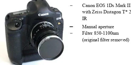
Figure 3. Properties of the near infrared sensitive camera
Additionally, one camera is modified to be sensitive in the near infrared region. Figure 3 shows the properties of the near infrared sensitive camera. The internal filter was removed and an 850nm low pass filter was attached.
The camera is now sensitive to light from 850nm to around 1100nm. This NIR sensitive band is mainly used for water detection in flood scenarios. The figure shows the Canon EOS 1Ds Mark II, whereas in the final version of the 4k system a NIR sensitive Canon EOS 1D-X will be installed.
In principle, the cameras of the 4k sensor are arranged to provide one nadir view and two oblique views. The oblique viewing angle is configurable freely with a maximum of 32°. There are two basic configurations.
In the first configuration the two oblique looking cameras have a small overlap in the nadir direction whereas the nadir looking camera, e.g. the NIR sensitive camera, is fully overlapping with the oblique looking cameras.
In the second configuration, all three cameras have a small overlap to reach the maximum FOV of 104°. Table 3 lists the viewing directions, the FOV, the coverages for two flight heights, and the GSD for each camera of the most common configurations.
A detailed discussion of the geometrical and radiometric properties of the cameras, the reached accuracies and a description of the real-time processing chain as it is installed at the 4k system is given in (Kurz 2012).
The real-time application scenarios for the 4k system are sketched (Kurz 2014).
Component Size [mm] Weight [kg] Properties
2 Microwave antenna (SRS1) 120120113 20.75 Bidirectional C band data link system with 11 Mbit/s eff. data rate, for distances up to 80km line-of-sight.
1 Network radio (SRS) 58120230 1.00
2 Amplifier (SRS) 78108220 21.60
3 Canon EOS 1D X/C cameras 158163.682.7 31.34 See table 2
3 Zeiss lenses ø72 length 65 30.53
1 IMU (IGI2 Aerocontrol IId) 200132137 2.10 Real-time GNSS/IMU measuring and processing unit, RMS position 0.1 m, yaw 0.05°, roll/pitch 0.01° 1 GPS/IMU processor (IGI) 65140205 1.80
1x Camera trigger box 19011060 0.6 Raspberry Pi3 minicomputer with
programmed trigger intervals
3 PC unit 43031090 8.5
1 Housing + plattform … 542869595 40.1 Carbon fiber hull, aluminum structure
Σ 81.4
Table 1. Properties of 4k system hardware components
1 SRS: Schulze Radio Systems http://www.srsw.de
2 IGI: Ingenieur Gesellschaft für Interfaces mbH http://www.igi.eu
̶ Canon EOS 1Ds Mark II
with Zeiss Distagon T* 25 IR
̶
Manual aperture̶ Filter 850-1100nm
(original filter removed)
Figure 4: Viewing configuration and footprints of the 4k system with different configurations
Canon EOS 1D-X (left/right) Canon EOS 1D-C (nadir) Lenses Zeiss Makro Planar 2/50, 2/100
Zeiss Distagon T* 35
Zeiss Makro Planar 2/50, 2/100 Zeiss Distagon T* 35
Sensor / Pixel size Full frame CMOS / 6.944µm Full frame CMOS / 6.944µm Image size 5184 x 3456 pixel, ratio 3:2
(17.9 MPix)
5184 x 3456 pixel, ratio 3:2 (17.9 MPix)
Image format JPEG (Canon L10-L1) RAW (14Bit)
JPEG (Canon L10-L1) RAW (14Bit)
4k movies 4096 x 2160 pixel, ratio 1.9:1
8.85 MPix
max. 24 fps / 4:2:2 YUV 8 bit 1.7 Gbps (uncompressed) 0.5 Gbps (MJPEG compressed)
ISO 100-204800 100-204800
Max. frame rate / max. images
14 fps / 180 images 14 fps / 180 images
Exposure time 30s – 1/8000s 30s – 1/8000s
Data interface LAN (EDSDK software interface) LAN (EDSDK software interface)
Table 2. Properties of the 4k cameras
Wide area RGB 50mm lense
RGB 50mm lense
RGB 100mm lense
NIR 25mm lense
4k video 35mm lense
4k video 50mm lense Viewing
directions 12 Nadir 32° 219° 29° Nadir Nadir Nadir
FOV 52° across,
13° along
38° across,
13° along
19° across,
7° along
36° across,
26° along
22° across,
12° along
16° across,
9° along
Coverage / GSD@500m
1280m 230m /
6.9cm nadir
780m 230m /
6.9cm nadir
344m 122m /
3.5cm nadir
720m 480m /
13.8cm nadir
404m 212m /
9.9cm nadir
286m 158m
6.9cm Coverage /
GSD@1000m
2560m 460m /
13.8cm nadir
1560m 460m /
13.8cm nadir
688m 244m /
7.0cm nadir
1440m960m/
27.6cm nadir
808m 424m /
19.8cm nadir
572m 316m
13.8cm
Table 3. Viewing geometry of six different sensor configurations
3. PERFORMANCE ANALYSIS
The focus in the following performance analysis lies on the accuracy of the GNSS/IMU system in the presence of enormous vibrations of the helicopter and on the effect of these vibrations to the 4k video quality.
3.1 Real-time GNSS/IMU
The sensor including the IMU is decoupled from the helicopter with four absorbers, which are installed between the outer pylon
and the sensor board within the pylon. Figure 5 shows exemplarily the amplitude spectrum of roll and pitch angle measured on the decoupled sensor board.
As expected the vibrations are higher when the helicopter hoovers compared to the forward flying case. In some cases, the spurious oscillation peaks of the rotor blades appear in the amplitude spectrum which are located at around 14 and 28Hz based on a rotational frequency of 7Hz.
Figure 5. Single-sided amplitude spectrum of roll and pitch angle measured on the decoupled sensor board. Upper left and right: helicopter is hovering. Lower left and right: helicopter goes with standard speed (~60m/s).
The spurious oscillation peaks of the rotor are marked.
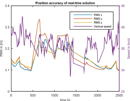
It is expected that these vibrations have influence on the final accuracy of the GNSS/IMU system. Therefore, the reached position accuracies are analysed for the real-time and the post-processing case. Figures 6 and 7 show exemplarily the theoretical accuracies of the position after a combined calculation of the position based on GPS and IMU measurements. In both cases, the reached accuracies are beyond the specified 0.1 m, and even in the post-processing case the accuracies are not increased. A direct comparison of both cases should not be made, as they are based on different data sets.
Figure 6: RMS of the sensor position in the real-time solution (left axis) and vertical speed of the helicopter (right axis)
Figure 7: RMS of the sensor position in the post-processing solution (left axis) and vertical speed of the helicopter (right
axis)
In some cases, the influence of the vertical speed on the RMS errors is visible as the RMS error increases when the vertical speed decreases.
RM
S
in
[m
]
Speed in
[m
/s]
R
M
S
in
[m
]
Speed i
n
[
m
/s
]
3.2 4k video
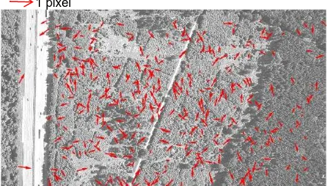
As mentioned before, the Canon EOS 1D-C camera is capable to acquire 4k videos. Due to the vibrations of the helicopter, the rolling shutter effect has a great impact on the quality of the 4k video. The rolling shutter effect is caused by the line-by-line acquisition of the CMOS sensor in combination with movements of the imaged object which are happening during the time one single frame is captured. Transferred to the helicopter sensor it follows that the rolling shutter effect is caused by movements of the camera with a frequency higher than the frame rate of 24 fps. In Figure 8, the rolling shutter effect is visualized by showing the distortions between two consecutive 4k video frames. For this, tie points are matched, a projective transformation between two frames is calculated and then the differences after transformation are plotted as arrows. Clearly visible is a rolling shutter effect which is caused by the 28Hz spurious oscillation of the rotor blades, as there is one movement in pitch direction in the upper third of the image and one movement in roll direction at the image bottom. The time difference (assuming that a frame is acquired within 1/24s) between two effects roughly corresponds to this 28Hz.
Figure 8: Image distortions between two consecutive 4k video frames if the helicopter hoovers. Arrows show the positional
difference after projective transformation.
Figure 9: Image distortions between two consecutive 4k video frames if the helicopter goes with standard speed. Arrows show
the positional difference after projective transformation. Figure 9 shows the image distortions between two consecutive 4k video frames but in difference to figure 8 with the helicopter going with standard speed. The remained distortions are all below 1 pixel, show no pattern, and are mainly caused to the changed viewing directions between two frames.
4. DISCUSSION
As presented in chapter 3, vibrations caused by the helicopter have great impact on the accuracy of the GNSS/IMU and on the quality of the 4k video stream. It was planned to reduce the vibrations by the absorbers which are installed on the sensor board. But first test flights have shown that these absorbers do not reduce the incoming vibrations sufficiently, at least not if the helicopter hoovers. The re-design of the sensor with better absorbers is one easy possibility to remedy the problem. The installation of a stabilization platform for the cameras would be another option but takes more efforts.
4.1 Status
In table 4, the status of the processors which are planned for 4k sensor is listed. Operationally installed are the automatic traffic data extraction (Leitloff 2014) and the mapping processor. Ongoing research topics are real-time person data extraction and real-time 3D generation. All data products can be sent to ground-station in real-time, except the 4k video stream.
real-time
* Possible with optical data link (Moll 2013) **Ongoing research
Table 4. Status of installed processors and downlink capability
REFERENCES
Gstaiger, V., Kurz, F., Hohloch, M., 2014: VABENE++
multi-sensor approach to support crisis management. In: International
Disaster and Risk Conference (IDRC), 283-286. Global Risk Forum GRF Davos. 5th International Disaster and Risk Conference IDRC 2014, 24.-28. Aug. 2014, Davos, Schweiz.
Kurz, F., Türmer, S., Meynberg, O., Rosenbaum, D., Runge, H., Reinartz, P., 2012: Low-cost optical Camera System for
real-time Mapping Applications. Photogrammetrie Fernerkundung
Geoinformation, 2012 (2), 159-176. DOI: 10.1127/1432-8364/2012/0109. ISSN 1432-8364.
Kurz, F., Rosenbaum, D., Meynberg, D., Mattyus, G., 2014:
Real-time mapping from a helicopter with a new optical sensor
system. In: Publikationen der Deutschen Gesellschaft für
Photogrammetrie, Fernerkundung und Geoinformation e.V., 23, 1-8. DFG. 34. Wissenschaftlich-Technische Jahrestagung der DGPF, 26.-28. März 2014, Hamburg. ISSN 0942-2870
Leitloff, J.,
Rosenbaum, D., Kurz, F., Meynberg, O., Reinartz, P., 2014: An operational system for estimating road traffic
information from aerial images. In: Remote Sensing, MDPI. In
review.
Moll, F., 2013: Free-space laser system for secure
air-to-ground quantum communications. SPIE Newsroom. DOI:
10.1117/2.1201311.005189. ISSN 1818-2259. 5 pixel
1 pixel