GEOREFERENCING OF TLS DATA FOR INDUSTRIAL INDOOR COMPLEX SCENES:
BEYOND CURRENT SOLUTIONS
Jean-Franc¸ois Hullo*a b, Pierre Grussenmeyera, Tania Landesaand Guillaume Thibaultb c a
The Image Sciences, Computer Sciences and Remote Sensing Laboratory INSA , 67000 Strasbourg, France bEDF R&D, 92141 Clamart, France
c
Laboratoire de Physiologie de la Perception et de l’Action, Coll`ege de France, UMR 7152, CNRS, Paris, France (jean-francois.hullo, pierre.grussenmeyer, tania.landes)@insa-strasbourg.fr, [email protected]
Commission V/3
KEY WORDS:TLS, primitive-based registration, indoor georeferencing, industrial installations, geolocation
ABSTRACT:
Current Terrestrial Laser Scanners (TLS) allow fast acquisitions of many dense point clouds. This technology is widely used within industrial complex scenes. The precise georeferencing of all the per-station point clouds is a crucial stage. Nowadays, the use of targets or tacheometry for precise georeferencing is time-consuming and then limits the number of surveys. The purpose of this article is to present and analyse a primitive based registration using points, lines and planes automatically extracted and paired in the station point clouds. Our tests highlight the advantages and the current limitations of this approach. We also discuss the recent, and probably future, improvements of indoor geolocation systems as possible ways of research for the georeferencing of TLS data into industrial complex scenes.
1 INTRODUCTION
Several industrial applications require as-built models of the whole or part of their installations (mostly indoor and complex as illus-trated in figure 1). The number of surveys increases, because the tools for analysis and simulations based on 3D data are becoming more numerous and powerful. The utility of the Terrestrial Laser Scanner (TLS) for 3D acquisition of industrial scenes, as point clouds, is now admitted. The current resolution and speed of the TLS make it possible to consider wide campaigns of dense and accurate measurement, i.e. hundreds of scans, or even more.
Though the GPS + IMU combination solved many problems of georeferencing for outdoor measurements, indoor georeferencing of TLS data remains a research topic.
Our contributions in this paper are the followings:
• A review of several registration techniques for indoor com-plex installations, cf. section 2;
• A description of a primitive-based registration algorithm, cf. section 3.
• A test on two typical scenes: description, results and discus-sion, cf. section 4;
2 3D POINT CLOUD ACQUISITION OF INDUSTRIAL SCENES
2.1 Current effective best practices
Constraints. Due to functional constraints of the installations, the time allowed for the acquisition of TLS data can be very short. However, the position accuracy of the global point cloud after registration must typically reach 1-2 cm. Georeferencing is frequently required to make data fusion and retrieval easier.
Best practices. Currently, inside wide and complex industrial scenes, the common practice to georeference station point clouds is based on tacheometry. Since only few known points exist, sur-veyors have to traverse across rooms and corridors to establish
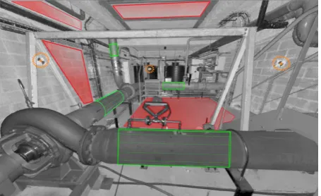
Figure 1: Typical station-based view of an industrial complex scene. Grey level: point cloud coded in intensity. Colour: recon-structed 3D primitives.
a control network. This method is time consuming with regard to the time of scanning but ensures the quality of the results. With the created network, surveyors are free to use targets to georeference directly, as discussed in (Lichti and Gordon, 2004) and (Scaioni, 2005), or indirectly, as presented in (Balzani et al., 2001).
Improvements. We aim at improving the previous methods in order to reduce the time of on-site acquisition and, as often as possible, to georeference without targets and total station.
2.2 Related works and selected approach
ICP.Many communities (such as Robotics, Computer Vision or reverse Mechanical Engineering) have worked on the registra-tion of point clouds. With the ICP, (Besl and Mckay, 1992) have defined a cloud-to-cloud approach which has since been widely used and adapted. Despite its improvements, this method cannot be used in our applications because: (a) the industrial scenes can be very regular; (b) the differences between point clouds from several stations can be large; and (c) the great number of stations and points per stations leads us to work with huge amount of data. Under those conditions, the accuracy of 1-2cm on the complete dataset cannot be reach by using the ICP or its current variants.
Keypoints. Targets are commonly used as keypoints for either registration or georeferencing of point clouds. In this case, the geometry of the network has to be designed before the acquisi-tion of TLS data. Another approach is presented in (Barnea and Filin, 2008): tiepoints are automatically extracted from range im-ages using local descriptors and a RANSAC is performed. In our configuration, few tiepoints can be extracted because the scene is composed of planar or smooth objects, mainly grey or metallic. Without enough details in geometry or texture of the scene, this approach does not lead to the required accuracy.
Geometric features for Photogrammetry. The feature-based approach is another method to overcome the targets for the reg-istration. Since 1980, several researchers in digital photogram-metry have argued for the use of 2D linear features instead of points, as (Schenk, 2004) explains. For terrestrial photogrammet-ric applications, linear features are commonly used for matching or pose (position and orientation of the sensor) estimation. Pro-jective geometry fully exploits the linear features, as presented and detailed in (Hartley and Zisserman, 2000) and (Forsyth and Ponce, 2002). This method for the registration of 2D images in-spired the feature-based registration of 3D TLS data.
Geometric features for TLS.The detection of linear features in TLS data, and their use for registration, is presented in (Jaw and Chuang, 2008b). (Rabbani and van den Heuvel, 2005) intro-duced a flexible registration using simultaneously several 3D ge-ometric entities (points, lines and planes) from 3D reconstructed primitives (mainly cylinder, sphere and plane). This approach was improved by (Jaw and Chuang, 2008a) by defining several constraints for the functional model and also a more complete stochastic model. An adaptation of those two works will be pre-sented in the section 3.
Prerequisites. Since TLS data are not directly used for the reg-istration in the feature-based approach, we first have to consider the stage of extraction and then the stage of pairing. Latest im-provements in the automatic extraction of 3D primitives in point clouds, (Schnabel et al., 2007) and (Rabbani et al., 2007), allow us to rely on the high level of automation and reliability of those methods. Pairing the 3D entities is a key point of the method. Indeed, the principle of bundle adjustment does not allow any wrong pairing. Therefore, it is important to check the exactness of pairing upstream of estimation of the poses. To correctly pair the entities, (Rabbani and van den Heuvel, 2005) constraint the search by using the geometric attributes of 3D primitives such as radius for cylinders or spheres. (Thapa, 2009) adds a semantic architectural constraint to pair windows and walls. The search interval for pairing is also limited by the uncertainty of the ap-proximate pose parameters of the stations. Although it does not ensure the existence of a solution for pairing problem, the con-straints on the search interval can drastically reduce the number of wrong pairs.
2.3 Using as many sources of information as possible
We have a corpus of information including data and uncertainty on it. We want to maximally exploit this corpus in the registra-tion. The method needs to be able to integrate many types of inputs:
• Approximate values of scan positions and orientations mea-sured with geolocation devices such as INS or odometer; • Bi-axial compensator;
• 2D maps of the civil works;
• A priori3D CAD model of the installation, especially civils; • Partial, less dense and/or non-updated previous point cloud; • Images or panoramas from calibrated or uncalibrated
cam-eras;
• Knowledge and surveyor’s estimation of his own position and heading.
By integrating all this information, the purpose is to help to calcu-late the pose parameters, to limit the search space of the unknown parameters and to improve the accuracy of georeferencing.
3 A PRIMITIVE-BASED REGISTRATION ALGORITHM
In this section, we present a feature-based registration approach, inspired by (Rabbani et al., 2007) and (Jaw and Chuang, 2008a).
3.1 Principle
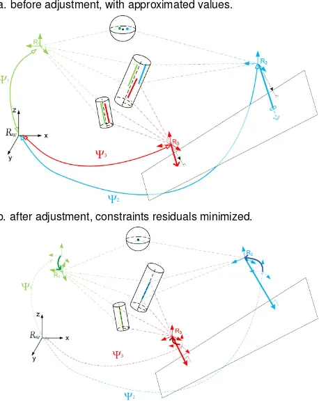
a. before adjustment, with approximated values.
b. after adjustment, constraints residuals minimized.
Figure 2: Principle of the current feature-based registration. In the scene: 3 stations, 2 lines, 1 point and 1 plane.
First, we have to choose an efficient parameterisation of the pose (position and orientation) of the stations. Efficient means here that we want to avoid dependency on the unknown parameters and to fit the geometric model to the nature of the uncertainty of the approximate values (measured with a geolocation system). Similarly, the choice of the parameterisation of the 3D primitives has to fit as well as possible the uncertainty of the point clouds and primitives reconstruction.
Thus, the stochastic and the functional (geometric) model are de-veloped using the technical specifications of the equipment. The definition of the constraints depending on the nature of the errors is also studied.
3.2 Parameterisation of the transformations
Definitions. We first define the global three dimensional Carte-sian coordinate systemgR={O,[~x, ~y, ~z]}, right-handed. The pose parametersΨsof a stationsare defined as the parameters of the frame transformation of any point fromgRto the attached
frame of the station sR, thenΨs = g→s
Ψ. The translation
ts = g→stis simply a three coordinate vector[txtytz]. As
de-tailed in (F¨orstner and Wrobel, 2004) and studied in (N¨uchter et al., 2010), many parameterisations can be used for rotations. In order to fit the hardware design of TLS, we use the three con-catenated rotations, of angles{ωφκ}, for a frame transformation respectively aroundx,yandz. This means that the3×3 rota-tion matrixg→sMused for frame transformation of a point from
gR
tosRcan be evaluated using the matrix relationg→sM =
M−ωM−φM−κ.
Approximate values of translations. In our configuration, we always have a 2D map of civil works and sometimes of major equipments and pipes. Due to construction tolerances, the errors of position of the walls can reach 5 cm in the worst case. Due lo-cal modifications, maps of equipments can be lolo-cally incomplete or not up-to-date. But this information can help the operator to approximate the position of the stations. For the z value, the height of the instrument is added to the altitude of the ground-floor. For the(x, y)value, the surveyor indicates the position of the station on a drawing of the civils.
To estimate the ability of surveyors to locate a ground point on a local map of civils, we carried out a psycho-experimental study whose results of this experiment allow us to make quantitative as-sumptions on the uncertainty of this type of approximations. Fif-teen students in topography of the INSA Strasbourg were tested. The experiment took place in the basement of the INSA Stras-bourg, considered as an indoor facility. Each student was guided through the building, from ground point to ground point. For each one of the 15 ground points, the student had to indicate on a local map the position of this ground point. The distance errors of the pointed locations is studied.
One student was rejected because of particularly incoherent re-sults. For the other 14 students, 75 percents of the points were closer than 50 cm to the true position. Only 4 percents of the an-swers were further than 1.5 m (fault).
In conclusion:stand.dev.(x, y) = 50cm andstand.dev.(z) = 15cm.
Approximate values of rotations. Currently, most laser scan-ners used for the acquisition of industrial scenes have a bi-axial compensator with range from 0.08◦
to 10◦
. Their accuracy varies from 0.015◦
to 0.00008◦
, depending on brands and models. Con-sequently, we can set, through calibration,(ω, φ) = 0with an uncertainty given by the manufacturer or by calibration. This as-sumption can also be found in (Reshetyuk, 2009). Regardingκ, since(ω, φ)⋍0, we can easily get an approximate value of the
κthrough the heading value of INS or IMU. However, our own experiments on a Crossbow AHRS440 have shown that this head-ing value can be strongly disturbed (up to 20◦
) with the proxim-ity (0 to 1 meter) of huge steel materials (such as pipes, turbines and large metallic objects). These metallic objects are commonly present in industrial scenes. Without a more reliable system for heading approximation, the registration algorithm must handle poor approximations forκ.
Selected parameterisation for the transformations. The pre-vious assumptions on the approximated values of the pose pa-rameters lead us to choose the following parameterisation of the transformations, involving 4 parameters: 3 translations and only 1 rotation. Consequently:Ψs={κ txtytz}.
3.3 Representation of the objects
In the scene, we can extract several 3D primitives: spheres (tar-gets), cylinders (pipes), polyhedron (walls and boxes) and possi-bly cones or torus. For the registration, we only consider 3 types of geometric entities: points, lines and planes. Typically we use points from targets or sphere centres, lines from cylinder axis and plane from polyhedron faces or walls.
Points.A pointPtis represented by its 3 Cartesian coordinates. For convenience, we use normalized homogeneous coordinates.
Lines.Many representations can be used. A line has only 4 de-grees of freedom, but most representations involve 6 parameters to avoid singularities. In our implementation we use the conve-nient normalized Pl¨ucker coordinates as defined in (F¨orstner and Wrobel, 2004) for the definition of the constraints. We mention (Schenk, 2004) who uses a 4 parameters representation, 2 orienta-tion and 2 posiorienta-tional parameters, which allows a better stochastic interpretation of line parameters but does not avoid special be-haviour for horizontal and vertical lines, mainly represented in our configuration.
Finally, we represent a lineLiwith two 3D vectors: u, its unit directional vector andv, a normal vector of the plane through the line and origin with length equal to the distance of the 3D line to the origin. Using two arbitrary distinct points(x,y)with Cartesian coordinates(x,y), we can easily computeuandv. The closest point to origin,w, can also be easily computed. ×is the vector product.
Planes. For a planePl, we use the Hessian normal form using unit normal vectorn = [n1n2n3]and the distancedfrom the origin. In summary:
3.4 Definition of the constraints
For the following relations, we use as notation for the entities: Frame
TypeID of entityStation of measure. For example line number 15 measured in the station 101 and expressed in the global frame has to be identical to line number 15 measured in the station 106 expressed in the global frame:gLi15101=
g
Li15106
study of frame transformations, let’s consider two frames1Rand matrix of rotation around the axis~zof angle−κ:
1→2
In the following relation,S(t)is the skew-symmetric matrix de-pending on a 3-vectortinducing the cross-product.
1
The constraints are defined as follows:
Points gPti1−
The current definition of the constraints is over parametrized for lines and planes and then brings dependencies between relations. The main issue of these dependencies concerns the estimation of thea posterioricovariance matrix.
3.5 Design of the system
Designing the system for bundle adjustment consists in building the Jacobian matrix (matrix of partial derivatives of constraints with respect to unknowns). Using 4 parameters instead of 6 al-lows us to get a lighter analytical expression of the transforma-tions, inverse transformations and derivatives intoMaxima (Shel-ter, 1998).
The idea is, for pairs of entities, to transform the coordinates of the entities from the station-based frame to a common (or “global”) frame and to use one of the two stations as reference to adjust the pose parameters of the second station.
We solve the system using least squares method, defined by the following relation:
δΨ = (AtP A)−1
(AtP e) (4)
whereδΨ is the residual vector, A the Jacobian matrix, P a weight matrix ande the enclosure vector. We add corrections to unknowns and iterate until convergence.
A weight matrix is used, but to properly handle the noise for points, lines and planes, we suggest in subsection 4.1 the use of a common noise factor to define weights.
4 STUDIES AND ANALYSIS
In this section, we assess the primitive-based registration approach defined previously. After the description of the simulations, we study two commonly existing configurations into industrial in-stallations: a corridor and a large hall. We compare the possible combinations of objects at several levels of noise. To focus our tests on the performance of the approach, we present here the registration of a simulated noisy data set on a reference data set (pairwise case). All the tests have been implemented using R, (Team, 2011).
4.1 Simulation of the noise
The initial data consist in point clouds measured from several sta-tions. 3D primitives are reconstructed and finally entities (points, lines and planes) are extracted. Then, the resulting error on the entities is function of: (a) the scanning error (hardware specifi-cations, scene configuration and scene materials) and (b) the re-construction error (number of points per reconstructed primitive, size of the visible part of the primitive from the station and perfor-mance of the algorithm of reconstruction). The expression of the noise on the entities must make sense with these two consecutive errors. Moreover, to properly handle several types of entities and their combinations, we define a common noise factor,σo, that
re-flects an identical level of uncertainty in the final reconstruction of the entities.σodoes not include the polar measurement errors
but an average cartesian measurement noise of the point cloud.
For the simulation of the data set, we carried out random sam-pling of the entities parameters following Gaussian distributions around “ground truth” parameters, as illustrated in figure 3.
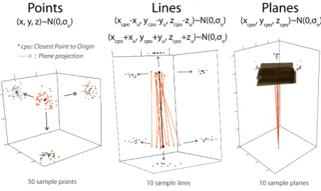
Figure 3: Stochastic models using a common noise factorσo.
Black: reference entities. Orange: sample interest points and sample entities. Brown: plane projections of sample interest points.
For a point,σo is the standard deviation of a normal
distribu-tion around the(x, y, z)coordinates of the reference point. For a line,σois the standard deviation of a normal distribution around
two points of the line: one meter below and one meter above the closest point to origin of the station-based frame. For a plane, σois the standard deviation of a normal distribution around the
(x, y, z)coordinates of the closest point of the plane to the origin of the station-based frame.
values of the pose parameters of the station, as introduced in the subsection 3.2, we adjust the pose using primitive-based con-straints as presented in the subsection 3.4. We do not study in these examples the influence of wrong matching of 3D entities.
4.2 First case: a typical corridor
Figure 4: First case: a typical industrial corridor. The scene includes planes, cylinders and targets from which we select 3 points, 7 lines and 5 planes.
The first configuration is a corridor (8 m×3 m×3 m, cf. figure 4), in which we set up 3 points, 7 lines and 4 planes in both the point cloud and the reference data set. These quantities reflect a fre-quent configuration for corridors. For each possible combination of type of entities and for several level of noiseσo, we sample 50
scenes around the reference data set.
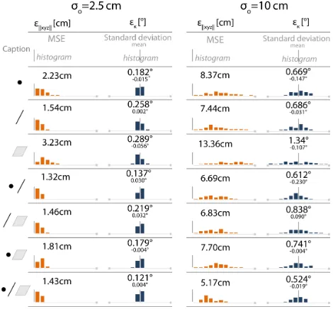
Figure 5: Errors in registration using 3D entities in the case of a corridor. 50 sample tests per case. Orange: error in position. Blue: error in orientation.
For the position, we compute the distance from registered station to reference station for the 50 sample scenes. In figure 5, we display the mean square error and the histogram of position errors for each combination and noise level. Since the orientation is 1-dimensional, we compute the error inκ. The standard deviation, the mean and the histogram of errors in orientation are displayed in figure 5.
We carried out the experiment for 8 values ofσo from 0 cm to
20 cm. For both position and orientation, the pose errors as func-tions ofσoare linear, as expected by the adjustment theory.
Con-sequently, for clarity, we only display two noise levels:σo= 2.5
cm andσo = 10cm. Most of the TLS data acquired for
indus-trial reconstruction purposes correspond to a noise level factorσo
between 0.1 cm and 5 cm.
4.3 Second case: a large hall
The second test case is a large hall (16 m×16 m×5 m) in which we set up 2 points, 11 lines and only one plane, the ground. The noise is simulated as previously described. For several levels of noise, we sample 50 scenes and we use all the features avail-able for the registration. The errors of position and orientation as function ofσoare also linear, as presented in figure 6.
Figure 6: Errors in registration using 3D entities in the case of a hall. 50 sample tests per case. Orange: error in position. Blue: error in orientation.
4.4 Discussion
First, the geometric model using constraints on 3D entities presents great results for two commonly seen configurations in industrial indoors. Our simulations highlight interesting properties of the approach: (a) no combination of 3D entities presented clearly larger errors; (b) the largest the number of used 3D entities is, the best are the results as expected; (c) the statistic properties of the errors did not reflect any degenerate configuration in the two presented tests.
However, degenerate configuration may be encountered, such as the trivial case of parallel lines. To avoid numerical instabilities (large enclosure vector and corrections), we recommend to use approximations of the pose parameters using geolocation system. The use of approximations also helps the convergence of the iter-ations by ensuring the validity of the linearisation in the Jacobian matrix. The use of many 3D entities with diverse directions and positions is the best way to avoid degenerate configurations. The noise of the 3D entities directly influences the quality of the esti-mation of the pose parameters.
The quality and the statistical behaviour of the results encourage us to develop the approach. However, since two over an infinity of configurations have been studied, we cannot generalize our results. A first development is the integration of many stations in a block estimation. Traverses, as pairwise series, can be easily handled using our present approach. A network configuration would yet require few adaptations in our method, especially in the consideration of several levels of uncertainty.
4.5 Toward a new approach for georeferencing indoor com-plex scenes using external information
Currently, the method uses as inputs some paired objects and ini-tial approximations of the pose parameters of the stations. As mentioned in subsection 2.3, more information is available and may help estimating the pose parameters. Parts of this informa-tion are always available: uncertainty on the approximainforma-tions of pose parameters, uncertainty on the reconstructed 3D primitives and uncertainty on the bi-axial compensator. Some other infor-mation will be sometimes, not always, available: images and 3D data (maps, previous point cloud or model).
The least squares method outputs adjusted values and cofactors. To help the surveyor making a decision during the acquisition stage, we could imagine other outputs such as probability maps of the solutions.
Current inputs and desired outputs lead us to study the probabilis-tic approaches to solve the problem of matching and registration, such as bayesian solver for SLAM used in (Montemerlo et al., 2002). The relevance and the use of these probabilistic methods are part of the future work of the authors.
5 CONCLUSIONS AND FURTHER WORK
In this article, we have presented a primitive-based registration algorithm using points, lines and planes. These 3D entities are extracted from reconstructed 3D primitives such as sphere, cylin-ders, planes or targets. The simulations confirmed the validity of the approach for two typical industrial indoor scenes: a corridor and a large hall. This validation is based on the quality of the out-puts (accuracy and precision) and on the flexibility of the method (combination of 3D entities). These tests on pairwise cases were necessary to study the possibilities of the approach which can then be extended to more stations using bundle adjustment.
However, the solver does not currently handle external informa-tion. Several types of information, such as geolocation systems ora prioriCAD models, should be used to guide the estimation of the pose parameters. The relevancy of a probabilistic approach to solve the problem has been discussed.
The authors future work will concern the following points: (a) the integration of multi-sources information; (b) a research of ef-ficient mathematical tools, including probabilistic methods, and (c) the integration of the primitive based registration in the pro-cess of TLS data acquisition.
REFERENCES
Balzani, M., Pellegrinelli, A., Perfetti, N. and Ucceli, F., 2001. A Terrestrial 3D Laser Scanner-Accuracy Tests. In: 18th Interna-tional Symposium CIPA, Postdam, pp. 445–453.
Barnea, S. and Filin, S., 2008. Keypoint based autonomous reg-istration of terrestrial laser point-clouds. ISPRS Journal of Pho-togrammetry and Remote Sensing 63(1), pp. 19–35.
Besl, P. J. and Mckay, N. D., 1992. A method for registration of 3-D shapes. IEEE Trans. Pattern Anal. Mach. Intell 14, pp. 239– 256.
F¨orstner, W. and Wrobel, B., 2004. Chapter 2 : Mathemati-cal concepts in photogrammetry in: Manual of Photogrammetry, Fifth Edition , pp. 35-53 and 111-165. ASPRS - MC-GLONE, J.-C. edn.
Forsyth, D. A. and Ponce, J., 2002. Computer Vision: A Modern Approach. Us ed edn, Prentice Hall.
Hartley, R. I. and Zisserman, A., 2000. Multiple View Geom-etry in Computer Vision. Cambridge University Press, ISBN: 0521623049.
Jaw, J. and Chuang, T., 2008a. Feature-Based Registration Of Terrestrial Lidar Point Clouds. ISPRS Commission III, WG III/3 XXXVII(3b), pp. 303–308.
Jaw, J. and Chuang, T., 2008b. Registration of Ground-Based Lidar Point Clouds By Means Of 3d Line Features. Journal of the Chinese Institute of Engineers 31(6), pp. 1031–1045.
Lichti, D. and Gordon, S., 2004. Error Propagation in Directly Georeferenced Terrestrial Laser Scanner Point Clouds for Cul-tural Heritage Recording. In: FIG Working Week, WSA2 Mod-elling and Visualization, Citeseer, Athens, p. 16.
Montemerlo, M., Thrun, S., Koller, D. and Wegbreit, B., 2002. Fastslam: a factored solution to the simultaneous localization and mapping problem. In: Eighteenth national conference on Artificial intelligence, American Association for Artificial Intel-ligence, pp. 593–598.
N¨uchter, A., Elseberg, J., Schneider, P. and Paulus, D., 2010. Study of parameterizations for the rigid body transformations of the scan registration problem. Computer Vision and Image Un-derstanding 114(8), pp. 963–980.
Rabbani, T. and van den Heuvel, F., 2005. Automatic point cloud registration using constrained search for corresponding objects. In: H. Kahmen and A. Gruen (eds), Proceedings of 7th Confer-ence on Optical, Vol. 1, Vienna, Austria, pp. 3–5.
Rabbani, T., Dijkman, S. T., Van Den Heuvel, F. and Vosselman, G., 2007. An integrated approach for modelling and global reg-istration of point clouds. ISPRS Journal of Photogrammetry and Remote Sensing 61(6), pp. 355–370.
Reshetyuk, Y., 2009. Self-calibration and direct georeferencing in terrestrial laser scanning. PhD thesis, Royal Institute of Tech-nology, Stockholm, Sweden.
Scaioni, M., 2005. Direct georeferencing of TLS in surveying of complex sites. In: Proceedings of the ISPRS Working Group V/4 Workshop 3D-ARCH “Virtual Reconstruction and Visualization of Complex Architectures”, Mestre-Venice, Italy.
Schenk, T., 2004. From point-based to feature-based aerial trian-gulation, 1. Introduction . ISPRS Journal of Photogrammetry and Remote Sensing 58(5-6), pp. 315–329.
Schnabel, R., Wahl, R. and Klein, R., 2007. Efficient RANSAC for Point-Cloud Shape Detection. Computer Graphics Forum 26(2), pp. 214–226.
Shelter, W., 1998. Maxima, a computer algebra system , version 5.18.1 (2009).http://maxima.sourceforge.net/.
Team, R. D. C., 2011. R: A Language and Environment for Sta-tistical Computing. R Foundation for StaSta-tistical Computing, Vi-enna, Austria. ISBN 3-900051-07-0.http://www.R-project. org.