THE PERFORMANCE ANALYSIS OF AN AKF BASED TIGHTLY-COUPLED INS/GPS
INTEGRATED POSITIONING AND ORIENTATION SCHEME WITH ODOMETER AND
NON-HOLONOMIC CONSTRAINTS
Kun-Yao Peng a, Cheng-An Lin a, *, Kai-Wei Chiang a
a Dept. of Geomatic, National Cheng Kun University, No.1, University Road, Tainan County 701, Taiwan –
Commission VII/7, III/2, V/1, V/3, ICWG V/
KEY WORDS: INS, GPS, Tightly-coupled, AKF, non-holonomic constraints
ABSTRACT:
INS/GPS integration scheme can overcome the shortcoming of GPS or INS alone to provide superior performance, thus this study implements a tightly-coupled INS/GPS integration scheme using AKF as the core estimator by tuning the measurement noise matrix
R adaptively. The AKF is based on the maximum likelihood criterion for choosing the most appropriate weight and thus the Kalman
gain factors. The conventional EKF implementation suffers uncertain results while the update measurement noise matrix R and/or the process noise matrix Q does not meet the case. The primary advantage of AKF is that the filter has less relationship with the priori statistical information because R and/or Q vary with time. The innovation sequence is used to derive the measurement weights through the covariance matrices, innovation-based adaptive estimation (IAE) in this study. The covariance matrices R are adapted in the study when measurements update with time. A window based approach is implemented to update the quality of GPS pseudo-range measurements by adaptively replace the measurement weights through the latest estimated covariance matrices R.
The use of odometer is particularly recommended when a low cost and precise vehicle localization system has to be implemented and there is the risk of GPS coverage failure, which is prone to happen when the vehicle enters a tunnel or cross deep valleys. Odometers are applied in land-vehicle navigation to provide augmented host velocity observations for standalone INS system in this study. There are two non-holonomic constraints (NHC) available for land vehicles. Land vehicles will not jump off the ground or slid on the ground under normal condition. Using these constraints, the velocity of the vehicle in the plane perpendicular to the forward direction is almost zero. EKF and AKF based tightly-coupled scheme with NHC is implemented in the study.
To validate the performance of AKF based tightly-coupled INS/GPS integration scheme with odometer and NHC, field scenarios were conducted in the downtown area of Tainan city. The data fusion of INS/GPS/Odometer/NHC can be used as stand-alone positioning tool during GPS outages of over 1 minute, and AKF based tightly-coupled INS/GPS integration scheme can be more stable combined with odometer and NHC during GPS outages of over 1 minute likewise.
* Corresponding author: C.A. Lin
1. INTRODUCTION
Global Positioning System (GPS) receivers require direct line of sight signals to the GPS satellite to provide navigation solutions with long-term stability; consequently, it is capable of providing continuous navigation solutions with uninterrupted signal reception. However, GPS leaves two scenarios to be considered in the land environment. The first one is intermittent signal reception, as for instance in heavily forested areas or in urban canyons. The other one is no signal reception at all, as for instance in buildings, tunnel or underground. In the first case, GPS has to be integrated with other sensors to bridge periods of no signal reception. In the second case, GPS has to be replaced by another navigation system that can provide continuous navigation solutions in above environments during no GPS signal reception.
On the contrary, Inertial Navigation System (INS) is widely used in many applications for navigating of moving platforms. Low-cost INS can experience large position and attitude errors over short term duration in comparison with high-grade systems. It has been proved through numerous researches that the INS/GPS integrated is the ideal technique for seamless vehicular navigation.
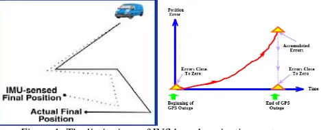
The stand-alone INS is self-contained and independent of external signals. Providing acceleration, angular rotation and attitude data at high sampling rates is the primary advantage of using INS in land vehicles. However, the disadvantage of using INS is that its accuracy degrades rapidly with time because of the accumulations of nonlinear errors and noises from accelerometers and gyros, as shown in Figure 1. Therefore, INS is used in the short-term case if no other navigation system or navigational aids is available.
Figure 1. The limitations of INS based navigation systems
The integrated system consisted of INS and GNSS takes advantage of the complementary attributes of both systems and
outperforms either stand-alone system operated (Yang, 2008). There are different integrated schemes including loosely-coupled, tightly-loosely-coupled, and ultra-tightly coupled INS/GPS integrated strategies, have been researched and developed since the last decade (Petovello, 2003).
The sustainability of INS/GPS integrated system using current commercially available micro-electro-mechanical systems (MEMS) inertial technology in typical GPS denied environments is fragile. However, the progress of MEMS inertial sensors is advanced rapidly thus the inclusion for general land vehicular navigation is bright in the future. In addition to waiting for the advanced development process of MEMS inertial sensor, some measures have been taken to increase the sustainability of MEMS INS/GPS integrated systems for vehicular applications during frequent signal blockages in software aspect (Chiang et al, 2003; Chiang and Huang, 2008). In other words, aiding the INS with other complementary sensors is critical to improve the accuracy of inertial based navigation systems. Choosing an appropriate estimation method is a key issue in developing an aided INS (Shin, 2005).
2. PROBLEM STATEMENTS
It is common practice to use Extended Kalman Filter (EKF) to accomplish the data fusion. Several architectures for EKF implementations are known (Wendel and Trommer, 2004). The most common integration scheme used today is loosely-coupled (LC) integration scheme. It is the simplest way of integrating a GPS processing engine into an integrated navigation system. The GPS processing engine calculates position fixes and velocities in the local level frame and then send the solutions as measurement update to the main INS EKF. By comparing the navigation solutions provided by INS mechanization with those solutions provided by GPS processing engine, those navigation states can be optimally estimated, as shown in Figure 2, the primary advantage of LC architecture is the simplicity of its implementation, because no advanced knowledge of GPS processing is necessary. The disadvantage of implementation is that the measurement update of the integrated navigation system is only possible when four or more satellites are in view.
Accelerometers (△v)
Gyroscopes (△ θ)
GPS
Corrections Corrections
INS KF
GPS KF
(position/velocity)
Gravity
Positions
Velocities
Attitudes
Figure 2. Loosely-coupled INS/GPS integration architecture
On the other hand, the tightly-coupled (TC) integration scheme uses a single KF to integrate GPS and IMU measurements. In the TC integration, the GPS pseudo-range and delta-range measurements are processed directly in the main KF, as shown in Figure 3. For some references, the aiding of the receiver tracking loops using velocity information provided by the INS
is an essential characteristic of tightly-coupled scheme, too. The primary advantage of this integration is that raw GPS measurements can still be used to update the INS when less than four satellites are available. This is of special benefit in a hostile environment such as downtown areas where the reception of the satellite signals is difficult due to obstruction when the vehicle navigates in urban or suburban area.
Accelerometers
(Δv)
Gyroscopes (Δθ)
GPS
(ρ or ϕ)
Corrections
Corrections
INS KF ∫
∫ ∫
Gravity
Positions
Velocities
Attitudes
Figure 3. Tightly-coupled INS/GPS integration architecture
However, according to Chiang and Huang (2008), the EKF implemented with a TC scheme may come with serious problems concerning the quality of GPS raw measurements. In other words, EKF based TC architecture is sensitive the quality of GPS raw measurements. This scenario usually takes place in urban and suburban areas because of the impact of reflected GPS measurements. Therefore, this study applied the Adaptive Kalman Filter (AKF) as the core estimator of a tightly-coupled INS/GPS integrated scheme by tuning the measurement noise matrix R adaptively. The idea of AKF is based on the maximum likelihood criterion for choosing the most appropriate weight and thus the Kalman gain factors. The conventional EKF implementation suffers uncertain results while the update measurement noise matrix R and/or the process noise matrix Q does not meet the case.
3. THE IMPLEMENTAION OF AKF SCHEMES The AKF can be implemented by Multi model adaptive estimation (MMAE) and Innovation-based adaptive estimation (IAE), respectively. Those methods need to calculate the innovation sequence, which is obtained by the difference between real measurement received by the filter and predicted value. At the current epoch k, not only the new measurement but the predicted value provides the new information. Hence, the innovation sequence represents the information satisfy the new measurement and considered as the most relevant source of the adaptive filter. See Genin (1970), Kailath (1972) and Kailath (1981) for more details. The primary advantage of AKF is that the filter has less relationship with the priori statistical information because the R and/or Q matrices vary with time.
According to Schwarz and Mohamed (1999), the IAE scheme is more efficient than MMAE scheme. Therefore, the IAE scheme is chosen in this study. The innovation sequence is used to derive the measurement weights through the covariance matrix
R in this study. In the IAE method implemented in study, the
covariance matrix R is adapted when measurements update with time. A window based approach is implemented to update the quality of GPS pseudo-range measurements by adaptively
replace the measurement weights through the latest estimated covariance matrices R. Figure 4 depicts the implementation of IAE procedure.
Figure 4. IAE computing procedure
In the IAE approach, the measurement covariance matrix R and system noise covariance matrix Q are tuned by measurements of different time. The study focuses on the influence of the qualities of measurements, so only the measurement covariance matrix R is variable. The formulations of AKF are shown below (R-only) (Schwarz and Mohamed, 1999).
)
Where
v
krepresents the innovation sequence andk
v
Cˆ
is the covariance of innovation sequence at epoch k. j0 is the firstepoch of estimation window, and it would be calculated by
j
0=
k
−
N
+
1
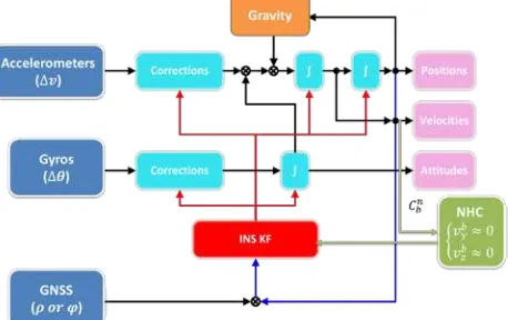
and N is the size of window.The integrated algorithm in this study is applied for land vehicle navigation. Therefore, the velocity of land vehicle navigation constraints is derived assuming that the vehicle does not slip, which is a close representation for travel in a constant direction. A second assumption is that the vehicle stays on the ground, i.e. it does not jump of the ground. If both assumptions are true, non-holonomic constraints (NHC) are defined as the fact that unless the vehicle jumps off the ground or slides on the ground, the velocity of the vehicle in the plane perpendicular to the forward direction is almost zero (Sukkarieh, 2000; Nassar et al., 2006; Godha, 2006). Figure 5 shows the scenario of non-holonomic constraints in the b-frame. Therefore, two constraints can be considered as measurement updates to the Kalman filtering navigation:
Figure 5. The two non-holonomic constraints in the b-frame
The body frame velocity can be given as:
n Perturbing Equation 5 expresses:
)
Collecting terms to the first order, the velocity error dynamics can be written as:
Then the measurement matrix can be given as:
T
In general, the velocity output of the inertial navigation mechanization
v
n can be transformed to the body frame velocityv
b by the attitude error dynamics DCMC
bn. And theNHC k
z
is used as the measurements in the Kalman filter. The estimated errors will be fed back to the mechanization then. Finally, the implementation of the Kalman filters with non-holonomic constraints in INS-based tightly-coupled integrated systems can be illustrated as Figure 6.Figure 6. INS-based tightly-coupled integrated systems with NHC
4. RESULTS AND ANALYSIS
To validate the performance of proposed algorithm, the field scenario of the land vehicle was conducted in the downtown area of Tainan. Reference and test systems were installed on the test vehicle. The geodetic GPS receiver with double frequency board and the low-cost GPS receiver with single frequency board were applied in the field scenario. In the case of INSs, the two tactical grade INSs were applied.
4.1 Test Instrument
Table 1 and Table 2 show the specifications of the GPS receivers and INSs used in the field scenario.
Table 1. The specifications of the GPS receivers NovAtel OEMV-3
Carrier Phase C/A Code Accuracy
(RMS)
SPP (m) L1:1.8 L1+L2:1.5 3.0
DGPS (m) 0.45 2.4
Table 2. The specifications of the INSs
Type of IMU Grade Gyro Drift Acc. Drift SPAN-CPT Tactical 1 deg/hr 0.75 C-MIGITS III Tactical 3 deg/hr 0.2
The reference system is the SPAN-CPT with NovAtel OEMV-3 integrated system. The reference solutions were computed by the single point positioning (SPP) solutions with Rauch-Tung-Striebel (RTS) smoother. The test systems are the C-MIGITS III with NovAtel OEMV-3 integrated system and C-MIGITS III with U-blox AEK-4T integrated system. And the test systems are implemented by the SPP solutions and the Kalman filters with non-holonomic constraints to integrate.
4.2 Field Scenario
The field scenario of the land vehicle was conducted in the downtown area of Tainan, and the total trajectory distance is 5 kilometers and the work time is 20 minutes. The trajectory is displayed in Google Earth as shown in Figure 7, and Figure 8 shows the building distribution and scenes beside the roads went through in the field scenario. The installed instruments on the top of the land vehicle can be shown as Figure 9.
Figure 7. Trajectory of the field scenario
Figure 8. Building distribution and scenes in the field scenario
Figure 9. Installation of the instruments
4.3 Results
The testing system is composed of the tactical INS (C-MIGITS III) with low-cost GPS receiver (U-blox) and a geodetic grade dual frequency GPS receiver, respectively. The integration algorithms to deal with the data fusion in this study are EKF, AKF, EKF with NHC and AKF with NHC. The reference system is the SPAN-CPT with geodetic GPS receiver integrated
system and the integrated algorithm is RTS smoother processed in post-mission with differential carrier phase measurements. For testing system, the GPS solutions are proceed with the SPP solutions. The PDOP values and visible satellite numbers of the geodetic GPS receiver and the low-cost GPS receiver in the field scenario are shown in Figure 10 and Figure 11.
Figure 10. PDOP and visible satellites of the geodetic GPS receiver
Figure 11. PDOP and visible satellites of the low-cost GPS receiver
4.3.1 Tactical INS & Geodetic GPS receiver
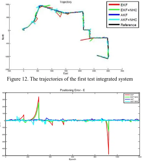
The first scenario is to demonstrate the results of tactical INS and geodetic GPS receiver processed by EKF, EKF with NHC, AKF and AKF with NHC, respectively. Figure12 shows the n-frame trajectories of the integration algorithms, and positional solutions errors in local level frame (East, North and Up directions) are shown in Figures 13 to 15.
Figure 12. The trajectories of the first test integrated system
0 200 400 600 800 1000 1200
-500 -400 -300 -200 -100 0 100 200 300 400
Epoch
E
rro
r
Positioning Error - E
EKF EKF+NHC AKF AKF+NHC
Figure 13. E-errors of the first test integrated system
0 200 400 600 800 1000 1200
-200
Positioning Error - N
EKF EKF+NHC AKF AKF+NHC
Figure 14. N-errors of the first test integrated system
0 200 400 600 800 1000 1200
-100
Positioning Error - U
EKF EKF+NHC AKF AKF+NHC
Figure 15. U-errors of the first test integrated system
Generally speaking, the positional errors estimated by NHC are significantly smaller than those estimated by EKF and AKF in East direction in most of the cases. On the other hand, the position errors of north components estimated by AKF+NHC are slightly smaller than those estimated by EKF in North direction in most of the cases. Similar trend can be founded in height components. Tables 3 and 4 illustrate the error statistics of the first test.
Table 3. Maximum errors of the first test integrated system
KF Maximum Error (m)
Table 4. RMS values of the first test integrated system
KF RMS (m)
4.3.2 Tactical INS & Low-cost GPS receiver
The second testing scenario is to analyze the results of the tactical INS with the low-cost GPS receiver proceed with EKF, EKF with NHC, AKF and AKF with NHC integration algorithms. Figure 16 shows the n-frame trajectories of the integration algorithm. The position errors can be plotted as shown in Figures 17 to 19, and their error statistics are illustrated in Tables 5 and 6.
Figure 16. The trajectories of the second test integrated system
0 200 400 600 800 1000 1200
-600
Positioning Error - E
EKF EKF+NHC AKF AKF+NHC
Figure 17. E-errors of the second test integrated system
0 200 400 600 800 1000 1200
-150
Positioning Error - N
EKF EKF+NHC AKF AKF+NHC
Figure 18. N-errors of the second test integrated system
0 200 400 600 800 1000 1200
-150
Positioning Error - U
EKF EKF+NHC AKF AKF+NHC
Figure 19. U-errors of the second test integrated system
Table 5. Maximum errors of the second test integrated system
KF Maximum Error (m)
Table 6. RMS values of the second test integrated system
KF RMS (m)
E N U
EKF 67.214 30.703 43.888
EKF+NHC 36.088 16.557 37.725
AKF 14.169 16.019 28.464
AKF+NHC 11.222 10.963 22.721
4.4 Analysis
The first test integrated system implements AKF with NHC can achieve 25% in horizontal position error and 25% in vertical position error in comparison with AKF based algorithm. The second test integrated system implements AKF with NHC can achieve 26% in horizontal position error and 20% in vertical position error from AKF based algorithm.
Comparing to the results of the first test integrated system (geodetic GPS receiver) and the second test integrated system (low-cost GPS receiver), similar improvement ration can be obtained. In the case of EKF based INS/GPS tightly-coupled integration with non-holonomic constraints, all the results in this field scenario have 40% up improvement in horizontal position error and 30% averaged improvement in 3D position error from EKF to EKF with non-holonomic constraints. In the other case of AKF based INS/GPS tightly-coupled integration with non-holonomic constraints; the results show the 25% averaged improvement in 3D position error.
From the results of EKF, EKF with NHC, AKF and AKF with NHC applied in the integrated systems, the non-holonomic constraints can improve the EKF and AKF based integration algorithms. Therefore, the aid of non-holonomic constraints to the Kalman filters applied in land vehicles can be reveal here, especially during no GPS signals.
5. CONCLUSION
The objective of this study is to implement EKF and AKF based tightly-coupled INS/GPS integrated system with non-holonomic constraints for land vehicles. 17-state EKF and 17-state AKF with non-holonomic constraints can raise the position accuracy especially during GPS signal obstructions for land vehicles.
The case of the 17-state EKF based tightly-coupled INS/GPS integrated system can reach 30% averaged improvement in 3D position error with non-holonomic constraints. The other case of 17-state AKF based tightly-coupled INS/GPS integrated system can reach 25% averaged improvement in 3D position error with holonomic constraints. Especially, the non-holonomic constraints can be the aid for the stand-alone INS to decrease the position drift during the GPS obstructions over 1 minute in those two cases of the INS integrated with the geodetic GPS receiver and the low-cost GPS receiver. Therefore, the AKF based INS/GPS tightly-coupled integrated algorithm with non-holonomic constraints can provide more stable navigation solutions than EKF and AKF based integration algorithms applied in a hostile environment.
6. REFERENCE
Brown, R.G. and Hwang, P.Y.C., 1992. Introduction to random signals, John Wiley and Sons, New York.
Chiang, K.W.; Noureldin, A.; El-Sheimy, N., 2003. A New Weight Updating Method for INS/GPS Integration Architectures Based on Neural Networks. Measurement Science and Technology, 15(10), pp. 2053-2061.
Chiang, K.W. and Huang, Y.W., 2008. An Intelligent Navigator for Seamless INS/GPS Integrated Land Vehicle Navigation Applications. Applied Soft Computing, Vol. 8, Issue 1, pp. 722-733.
Gelb, A., 1974. Applied Optimal Estimation. MIT Press, Cambridge, England.
Genin, F., 1970. Further comments on the derivation of Kalman filters, section II: Gaussian estimates and Kalman filtering. In: Leondes CT (ed) Theory and applications of Kalman filtering, AGARDOgraph 139, NATO Advanced Groups for Aerospace R&D.
Kailath, T., 1972. A note on least squares estimation by the innovation method. Soc Ind Appl Math 10(3), pp. 477-486.
Kailath, T., 1981. Lectures on Wiener and Kalman filtering, CISM courses and lectures no. 140. Springer, Berlin Heidelberg New York.
Lewantowicz, Z.H., 1992. Architectures and GPS/INS integration: impact onmission accomplishment, IEEE Aerospace and Electronics Systems Magazine; 7 (6) 16.
Schwarz, K.P. and Mohamed, A.H., 1999. Adaptive Kalman Filtering for INS/GPS, Journal of Geodesy 73, pp. 193-203.
Wendel, J. and Trommer, G.F., 2004. Tightly coupled GPS/INS integration for missile applications, Aerospace Science and Technology 8, pp. 627–634.
Barbour, N. and Schmidt, G., 2001. Inertial Sensor Technology Trends, IEEE Sensors Journal, Vol. 1, No. 4, pp. 332-339.