THE ROLE OF ASTRO-GEODETIC IN PRECISE GUIDANCE OF LONG TUNNELS
Mirahmad Mirghasempoura, Ali Yaser Jafarib
a Dept. of Civil Engineering, Shahid Rajaee Teacher Training University, Tehran, Iran – [email protected] b Dept. of Architecture and Urbanism, Shahid Rajaee Teacher Training University, Tehran, Iran – [email protected]
KEY WORDS: Astro-geodetic, TZK2-D, Underground surveying, vertical deflection.
ABSTRACT:
One of prime aspects of surveying projects is guidance of paths of a long tunnel from different directions and finally ending all paths in a specific place. This kind of underground surveying, because of particular condition, has some different points in relation to the ground surveying, including Improper geometry in underground transverse, low precise measurement in direction and length due to condition such as refraction, distinct gravity between underground point and corresponding point on the ground (both value and direction of gravity) and etc. To solve this problems, astro-geodetic that is part of geodesy science, can help surveying engineers. In this article, the role of astronomy is defined in two subjects:
1- Azimuth determination of directions from entrance and exit nets of tunnel and also calibration of gyro-theodolite to use them in Underground transvers: By astronomical methods, azimuth of directions can be determine with an accuracy of 0.5 arcsecond, whereas, nowadays, no gyroscope can measure the azimuth in this accuracy; For instance, accuracy of the most precise gyroscope (Gyromat 5000) is 1.2 cm over a distance of one kilometre (2.4 arcsecond). Furthermore, the calibration methods that will be mention in this article, have significance effects on underground transverse.
2- Height relation between entrance point and exit point is problematic and time consuming; For example, in a 3 km long tunnel ( in Arak- Khoram Abad freeway), to relate entrance point to exit point, it is necessary to perform levelling about 90 km. Other example of this boring and time consuming levelling is in Kerman tunnel. This tunnel is 36 km length, but to transfer the entrance point height to exit point, 150 km levelling is needed. According to this paper, The solution for this difficulty is application of astro-geodetic and determination of vertical deflection by digital zenith camera system TZK2-D. These two elements make possible to define geoid profile in terms of tunnel azimuth in entrance and exit of tunnel; So by doing this, surveying engineers are able to transfer entrance point height to exit point of tunnels in easiest way.
1.1 Introduction
Tunnel construction for transport and other usage have existed for centuries. They have been developed both in urban environments for mass traffic transports and in interurban environments. Tunnels are long and deep, especially in mountainous regions. Surveying represents an important role within these tunnels’ lifecycles by applying different technologies and methodologies, for different purposes, from the guidance of new tunnels to the monitoring of old ones (Boavida et al, 2012). Astro-geodetic technique is one of the oldest and the most fundamental technique can be used for this application. The complete astro-geodetic works have a significant influence on the tunnel construction expenses, starting with the preparation of project documentation, tunnel cutting, staking out the route axis, control of work performance and surveying the completed situation (Zrinjski, 2006).
Until the middle of the last century, exclusively astro-geodetic methods allowed the absolute determination of longitude and latitude related to the global terrestrial coordinate system. Essential early applications were positioning (e.g. on expeditions), orientation of geodetic networks or reference ellipsoids, determination of geoid profiles using the method of astronomical leveling (Hirt and Bürki, 2006). Major improvements of astro-geodetic observation techniques could be achieved since the 1970’s when transportable photographic zenith cameras were successfully designed and constructed at the University of Hannover to determine vertical deflection component (Hirt et al, 2010).
Moreover, tunneling projects frequently involve the construction of long tunnels whose azimuths are to be determined very accurately, particularly prior to holing. Although conventional
traverse methods may be employed, generally, these cannot guarantee the accuracy required and contractual conditions may then specify that independent gyro-theodolite bearings must be obtained (Whetherelt and Hunt, 2002). So to do this operation exactly, the gyro-theodolite must be calibrated.
This research has yielded that astro-geodetic methods provide a fast result in controlling and for guidance of tunnel excavation.
1.2 Theory and Concept
In this research the role of astro-geodetic in precise guidance of long tunnels have been dealt in two main subjects:
1.2.1 ∆H determination
Initial relative positioning results using the satellites of the Global Position system (GPS) encourage users to compute orthometric height differences, ∆H= H2-H1, by the use of well-
known relation (Hein, 1984):
H2-H1: (h2-h1) - (N2-N1) (1)
Or ∆H12= ∆h12 -∆N12
Where ∆h=h2-h1 is difference in ellipsoidal heights and ∆N= (N2 -N1) is the difference in geoid heights. Whereas ∆h can be derived by GPS with an accuracy of 0.1 ppm, ∆N has to be determined using other data sources and formulas that will be mentioned. But the main problem is ∆H1,2 determination in long tunnel, because when entrance point height is known, to have exit point height, surveyors must do geometry levelling several kilometre more than the tunnel length especially in mountainous areas. So in this way, astro-geodtic can help surveyors to determine ∆H1,2 and after that engineers are able to calculate exit point height without The International Archives of the Photogrammetry, Remote Sensing and Spatial Information Sciences, Volume XL-1/W5, 2015
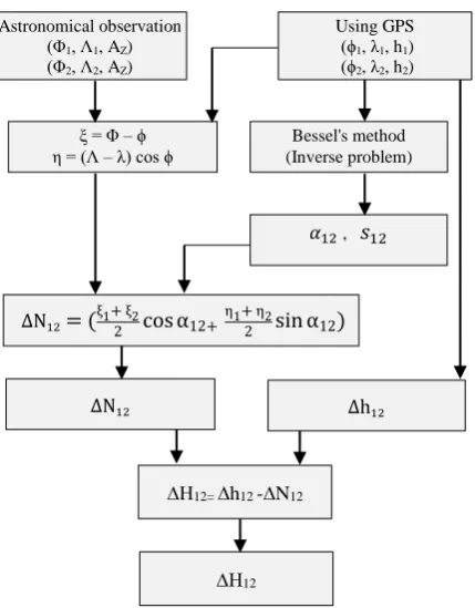
long time consuming. According to this research steps of ∆H1,2 determinationwill be as the below diagram:
1.2.2 Calibration and Correction in gyro-theodolite As known gyro-theodolite measure horizontal angles from the astronomical North (astronomical Azimuth) with an accuracy of ±3 (Lewén, 2006; Lambrou and Pantazis, 2004). The gyroscope theodolites used to be calibrated before and after their use in an arranged time period frame for their proper function. This is a very important check, which ought to be done carefully and repeatedly. So in this research 5 correction will be introduced to in order to assure the proper function of the instrument and the correct value of the measured astronomical azimuth.
After calibration of gyroscope and applying required correction to examine whether determined azimuth is right or wrong, that azimuth will be compare to the azimuth determined by astronomical (with an accuracy of 0.5‟) method.
1.3 Data processing
1.3.1 Vertical defelection components
The astronomical coordinates (Φ, Λ) is obtained by means of direction measurements to celestial objects, primarily stars, whose equatorial coordinates right ascension α and declination δ are given in the International Celestial Reference System ICRS. Longitude Λ and latitude Φ define the spatial direction of the plumb line with respect to the International Terrestrial Reference System ITRS (Fig. 1). ITRS and ICRS are linked by Greenwich Sidereal Time GAST being a measure for Earth’s rotation phase angle. Astro-geodetic methods use the equivalence of astronomical coordinates (Φ,Λ) and equatorial coordinates (α,δ) for a star exactly located in zenith (Farzaneh, 2009) or other directions. When we observe star in zenith direction the equation will be: Φ = δ , Λ = α – GAST (2) But for stars in other than the zenith direction, the geodetic coordination can be calculate by reading star height and time.
Vertical deflections (ξ, η) are directly obtained by calculating the difference between astronomical coordinates and geodetic coordinates (ϕ, λ) to be determined with GPS.In linear
approximation, the components (ξ, η) are usually computed as (Hirt et al, 2010): CT= Correction Term
ξ = Φ –ϕ+CT , η = Λ –λ cos ϕ+CT (3)
Nowadays these components can be determined with GPS and Digital zenith camera (Abedini, 2015).
1.3.2 Geodetic azimuth (� and distance �
We can compute geodetic azimuth by using inverse problem equation that could be called Bessel Bessel's method and have a history dating back to F. W. Bessel's original paper on the topic titled: 'On the computation of geographical longitude and latitude from geodetic measurements.
Inverse problem
In this problem we are given P1(φ1,λ1) and P2 (φ2,λ2) With the ellipsoid constants a, f, b= a (1-f ), e2= f (2-f ) and �ˊ = e
−e (Fig 2) and (Fig 3).
Figure 1. Astronomical coordinate and observation
Figure 3. Geodesic on auxiliary sphere Figure 2. Geodesic on ellipsoid
Diagram 1. Basic principle of ∆H determination
Astronomical observation
(Φ1, Λ1, AZ) (Φ2, Λ2, AZ)
Using GPS
(ϕ1, λ1, h1) (ϕ2, λ2, h2)
ξ = Φ –ϕ
η = (Λ –λ) cos ϕ (Inverse problem) Bessel's method
� , �
ΔN = ξ + ξ cosα + η + η sin α
ΔN Δh
∆H12= ∆h12 -∆N12
∆H12
A. Compute reduced latitude 1and 2 of P1 and P2 from
Tan = − tan φ (4) B. ωompute the longitude difference Δλ on the ellipsoid Δλ = λ2–λ1 (5)
C. ωompute the longitude difference Δ on the auxiliary sphere between P1 to P2 by iteration using the following sequence of equations until there is negligible change in Δ .
Sinσ = √�� � and cosσ. This will give −180̊ < σ ≤180̊.
�� �
=
(cos 2 sin Δ )2+ (cos
1 sin 2- sin 1 cos 2 cos Δ )2 (6)Cos σ = sin 1sin 2+ cos 1cos 2cos Δ (7)
Tan σ= �� �
c s �
Sin aE = ��� COS si Δ
si � (8) Cos 2σm = cos σ- si si
� � ��
(9)
Δ = Δλ + -C) f sin aE {σ+ C sin σ[ cos σm +
C cos σ - 1+2 cos σ )]} (11)
Where:
C= �6 � �� (4+f (4- 3 � ��) (12)
The first approximation for Δ in this iterative solution can be taken as Δω ≃Δλ
D. Compute the reduced latitude of the geodesic vertex from Cos = sin �� (13)
E. Compute the geodesic constant � from
� = ˊ �� (14)
F. ωompute Vincenity’s constants Aˊ and Bˊ from
Aˊ=1+ 6 8� + � (− + � − � ) (15)
Bˊ= � + � (− + � − � ) (16)
G. Compute geodesic distances s from
Δσ= Bˊ sinσ {cos2σ + Bˊ [cosσ 2 � σ − −6 Bˊ cos2 σ (-3+4�� σ) (-3+44 � σ ]} (17)
� =bA (σ- Δσ (18)
H. So finally the geodetic azimuth will be:
Tan � = � � si Δ
c s si −si c s c s Δ (19) I. Compute azimuth � from
Tan � = � � si Δ
−si c s +c s si c s Δ (20)
So reverse azimuth � will be
� = � ± ̊ (21)
1.3.3 Geoid undulation (∆N)
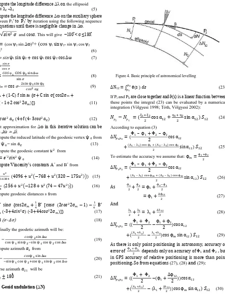
The basic principle of astronomical levelling gives us a definite mathematical relationship between geoid undulations and vertical deflection (Vӧlgyesi, 2005; Tse and Bâki Iz, 2006, Ceylan, 2009). According to the notations of Figure 4 we get:
dN =ϑds (22) where ϑ is the Pizzetti-type deflection of the vertical in the
azimuth α. ψetween any points P1 and P2 the geoid height change is:
ΔN12 = ∫ ϑ s � (23)
If Pi and Pkare close together and ϑ(s) is a linear function between these points the integral (23) can be evaluated by a numerical integration (Völgyesi 1998; Tóth, Völgyesi 2002):
� − � = ξ + ξ cos α +η + η sin α ) � (24)
According to equation (3)
∆� = Φ – ϕ + Φ – ϕ cos α
+ Λ – λ c s ϕ + Λ – λ c s ϕ sin α ) � (25)
To estimate the accuracy we assume that: ϕ =ϕ +ϕ
∆� = Φ – ϕ + Φ – ϕ cos α
+ Λ – λ c s ϕm + Λ – λ c s ϕmsin α ) � (26)
As ϕ +ϕ = ϕ +ϕ −ϕ
= ϕ +∆ϕ (27) And
λ +λ = λ +∆λ (28)
∆� = Φ + Φ −ϕ + ϕ cos α
+ Λ +Λ −λ +λ cos ϕ sin α ) � (29)
As there is only point positioning in astronomy, accuracy of error of Φ + Φ depends only on accuracy of Φ and Φ , but in GPS accuracy of relative positioning is more than point positioning. So from equations (27), (28) and (29):
∆� = Φ + Φ − ϕ +∆ϕ cos α
+ Λ +Λ − λ +∆λ cos ϕ sin α ) � (30)
So from determined geodetic azimuth and geodesic distance from equations (18) and (19), ∆N12 can be computed. After that from the equation ∆H12= ∆h12 -∆N12, surveyors can determine ∆H12 and due to known entrance point height, by using the equation ∆H12= H2- H1, exit point height is computable.
Figure 4. Basic principle of astronomical levelling
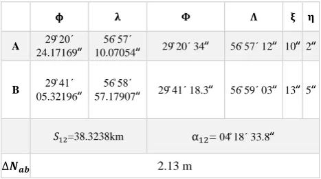
As an example for mentioned equations, in Kerman tunnel according to table 1, estimated ∆� was 2.13 m. Baesd on accuracy of astronomical point positioning and Gps about 0.2‟, if we assume that the maximum error for ξ and η is 0.4‟, when
we change this value for ξ and η, the ∆� value change below
5 cm, that is acceptable for administrative project. Morever, Length between entrance and exit point is the important factor that cause error, For instance, in above example for Kerman tunnel, if we assume 3 km instead of 38 km for tunnel length, the error will change in under 1 cm.
Table 1. Kerman tunnel parameters
1.4 Correction in gyro-theodolite
1.4.1 Geodetic correction
The quality of geodetic networks for guiding Tunnel inside long tunnels depends largely on the correct use of a gyroscope. The gyroscope theodolite or gyro-theodolite has a built-in free swing and fast rotation gyroscope that vacillates automatically provides astronomical azimuth (Lambrou and Pantazis, 2004). But the determined azimuth with gyro-theodolite is less accurate than the determined azimuth by astronomical methods.
So to control and check the accuracy of azimuth determined by gyro-theodolite, astronomical observation and gyro-theodolite observations should be compare. By the comparison, the necessary geodetic correction can be applied to gyro-theodolite results. the following corrections must be applied to reduce such observations to grid bearings:
A. Correction for polar motion (actual pole to CIO pole) B. Arc to chord correction
C. Convergence of the meridian D. Instrumental corrections
E. Correction for the deflection of the vertical
That astronomical observation in relation to items (A), (D) and (E) can help surveyor engineers to apply the correction. The following details can be added concerning these corrections:
1.4.1.1 Polar motion
The earth rotation axis will not remain fixed with respect to the earth body, rather move periodically around a certain mean axis. Such movement of the earth rotation axis is called Polar motion. Due to polar motion, it is important to reduce all observations so they refer to a certain mean pole. The most widely used mean pole is the International Convention of Origin (CIO), which is defined as the mean position of the instantaneous pole during the period 1900 to 1905.However, the deviation between an arbitrary rotation axis and the rotation axis corresponding to CIO is less than 0.1 mgon and therefore this correction is neglected (Lewén, 2006).
1.4.1.2 Arc to chord correction
The arc to chord corrections is applied by reference to formulae of the projection concerned. This correction is negligible for short distances.
1.4.1.3 Convergence of the meridians
Bearing of theodolite telescope will vary from point to point (Lewén, 2006). Thus as one proceeds along a straight line set out by a theodolite on the earth’s surface, the bearing of the line will not remain constant but will gradually alter. In latitudes in the neighbourhood of 60̊, the alternation amounts to almost a minute of arc in a line of one kilometre in lengths, and in higher latitudes the alteration is even bigger.
When one is using a gyro, the above stated problem is reversed. A gyro will in fact seek out and eventually settle in a meridian (true north) but when one wants to implement the gyro observations on a predefined map grid one has to keep in mind that the observed meridian only coincides with the map grid along the middle meridian of the map grid. The further east or west one gets from the middle meridian the larger the deviation between direction of North of the map grid and the meridian of longitude that the gyro shows.
This deviation (c) may be calculated using the following formula: Tanc = tan (λ −λ ∗sinϕ (31) Where:
ϕ = latitude of gyro position, λ = longitude of gyro position λ0= longitude of the middle meridian of the map grid system
1.4.1.4 Instrumental corrections
An alignment error can exist between the indicated heading of the gyroscope and the horizontal optical axis of the theodolite. This constant error can be determined at a measuring range where the azimuth is known.
1.4.1.5 Correction for the deflection of the vertical
The influence of the irregularity of the earth’s gravitational field (deflection of the vertical) thus merits special attention in regions where the deviation of the vertical is suspected to be large. A study of this problem has been carried out for the St Gotthard and Lötschberg tunnels (Carosio et al., 1997). Because of the length of the tunnels, gyroscopic observations are needed in addition to conventional methods. However, in a mountainous area such as the St Gotthard range, the effects of the variation of the earth’s gravitational field are not negligible. Experiments have thus been carried out on the effects of such variations on gyroscopic azimuths. The instrument that was used in these experiments was the Gyromat 2000 supplied by Deutsche Montan Technologie (DMT) of Bochum. This instrument has a measuring time of 8 minutes, with a nominal precision of 0.7 mgon.
The application of this correction allows an astronomical azimuth to be converted to geodetic azimuth, as follows (Heiskanen and
η is the east-west component of the deflection of the vertical ξ is the north-south component of the deflection of the vertical φ is the geographical latitude
z is the zenith distance to the observed point
In the case of a tunnel, where the lines of sight are approximately horizontal, cot z = 0, will only the η component of the deflection account to the correction.
Conclusion
This study presented functions for the determination of ∆H between entrance and exit point of tunnel and opened new perspective for guiding long tunnel and geodetic correction and calibration of gyro-theodolite based on astro-geodetic method. In spite of fact that the geometric levelling is time consuming, astronomical can be accomplished in a much shorter time interval. Using astrogeodetic cost in guidance of tunnel with a higher and more valuable amount information and quality. Th shortened surveying can be, by itself, a major advantage in most cases and can also be a decision issue. Furthermore By astronomical methods, azimuth of directions can be determine with an accuracy of 0.5 arcsecond, whereas, nowadays, no gyroscope can measure the azimuth in this accuracy.
Morever, If gyro observation are to be used in an adjustment to improve the network, it is very important that the observations are checked within themselves, i.e.that all corrections are applied and that the surveying and computation methods are such that the influence of gross and systematic errors are minimized.
REFERENCES
Abedini, A., Farzaneh, S., 2014. New approach for vertical deflection determination using digital Zenith cameras. Iran Geophysic. 9(1), pp. 29-15.
Baovida, J., Oliveira, A., Santos, B., 2012. Precise long tunnel survey using the Riegl VMX-250 mobile laser ranging system. Conference of riegl lidar 2012.
Ceylan, A., 2009. Determination of the deflection of vertical components via GPS and leveling measurement: A case study of a GPS test network in Konya, Turkey. Scientific Research and Essay. 4 (12), pp. 1438-1444.
Deakin, R. E., Hunter, M. N., 2009. Geodesics on an ellipsoid - ψesselˊ method. School of Mathematical & Geospatial Sciences, RMIT University publication, Melbourne, Australia.
Hein, G. w., 1985. Orthometric height determination using GPS observation and integrated geodesy adjustment model. NOAA technical report NOS 110 NGS 32, NOAA technical publication, USA.
Hirt, C., Bürki, B., Somieski, A., Seeber., G., 2010. Modern determination of vertical deflections using digital zenith cameras. Surveying Engineering. 136(1), PP. 1-12.
Krakiwsky , E.J., 1995. Thomson, D.B., Geodetic position computation. Department of Geodesy and Geomatics Engineering University of New Brunswick publication, Canada.
Lewén, I., 2006. Use of gyrotheodolite in underground control network. Master’s of Science Thesis in Geodesy. Royal Institute of Technology, Stockholm, Sweden.
Lambrou, E., Pantazis, 2004. Accurate Orientation of the Gyroscope’s ωalibration System. FIG Working Week meeting, Athen, Greek.
Tse, C. M., Bâki Iz, H., 2006. Deflection of the Vertical Components from GPS and Precise Leveling Measurements in Hong Kong. Surveying Engineering. 132(3), pp. 97-100.
Völgyesi, L., 2005. Deflections of the vertical and geoid heights from gravity gradients. Acta Geodaetica et Geophysica Hungarica. 40(2), pp. 147-157.
Velasco- Gómez, j., Prieto, J. F., Molina, L., Herreo, T., Fábrega, j., Pérez-Martin, E., Use of the gyrotheodolite in underground networks of long high-speed railway tunnels. http:// www.maneyonline.com/doi/abs/10.1179/1752270615Y.000000 0043?journalCode=sre.