AUTOMATIC CONSTRUCTION OF HIERARCHICAL ROAD NETWORKS
Weiping Yang
Geoprocessing, Esri, Inc. Redlands, USA - [email protected]
Commission II, WG II/2
KEY WORDS: Geospatial feature patterns, network analysis, road network hierarchy, street patterns, neighbourhoods, data enrichment
ABSTRACT:
This paper describes an automated method of constructing a hierarchical road network given a single dataset, without the presence of thematic attributes. The method is based on a pattern graph which maintains nodes and paths as junctions and through-traffic roads. The hierarchy is formed incrementally in a top-down fashion for highways, ramps, and major roads directly connected to ramps; and bottom-up for the rest of major and minor roads. Through reasoning and analysis, ramps are identified as unique characteristics for recognizing and assembling high speed roads. The method makes distinctions on the types of ramps by articulating their connection patterns with highways. Major and minor roads will be identified by both quantitative and qualitative analysis of spatial properties and by discovering neighbourhood patterns revealed in the data. The result of the method would enrich data description and support comprehensive queries on sorted exit or entry points on highways and their related roads. The enrichment on road network data is important to a high successful rate of feature matching for road networks and to geospatial data integration.
1. INTRODUCTION
1.1 Road Network Data and the Lack of Thematic Attributes
Roads connect cities, towns, and rural areas, serving transportation needs between settlements and events. Depending on traffic services a road is designated to provide, and geographic extents the road covers, a road network as a whole manifests a strong hierarchical nature, with sparsely distributed high speed roads sitting at the top level and densely clustered local streets forming the bottom of the hierarchy. In the information era, road network data is deemed to be one of the most sought-after necessities in urban planning and development, and routing applications for emergency response, goods delivery, and field work dispatch. With the increasing availability of data sources and demands for web-based traffic services, road network data equipped with the very nature of hierarchy to support advanced analysis and queries would be of great value.
In GIS (Geographic Information Systems) communities, road network datasets are commonly available from well-known sources, such as government agencies or private data providers. They will be presented at varying quality statuses, with or without being classified as highways, ramps, major roads, or local streets. When received as linear features with attributes for sub-classifications of road types, the completeness, accuracy, and consistence of these attributes are often unwarranted. More often, however, a given dataset would have no road type attribution in its features. Furthermore, a network dataset is usually populated with piecemeal road segments in need of assembly to be recognized as connected roads. For this kind of raw data containing only geometry, it becomes quite puzzling to know what features belong to a single road. The difficulty will certainly be aggravated when roads are in irregular shapes. Without an integrated hierarchical network structure comprised of complete and connected roads, the raw network data are far from suitable for comprehensive and meaningful network analysis, navigating simulations, planning, and management.
Obtaining thematic attributes for the classification of roads and preserving them in a database are costly and time consuming. On the other hand, given a set of lines depicting roads, it can be naturally perceived with observations, that which lines are connected to form highways, how highways are transmitted to and from major roads, or how clusters of minor roads can be accessed through major roads and highways. One of the questions to ask is: is it possible to know all these automatically?
1.2 Related Research on Road Network and Patterns
Road networks are conventionally represented through Euclidean planar graphs in which a graph G of a network is composed of E and N, as G(E, N). The component E is a set of unordered edges representing road segments and the component N a set of terminal vertices, embedded in the Euclidean plane depicting places. As roads meet at places, edges intersect at nodes. This graph of mapping roads to edges and intersections to nodes is “primal” in that there exists coherence between the dimensions of geographic and graph entities (Porta et al 2006). Alternatively, an opposite representation takes graph edges for places and nodes for roads. This results in a “dual” of the primal graph (Porta et al 2004). Due to the simplicity of storing graphs in graph-theoretic data structures and its excellent properties in modelling neighborhood connections, graphs are widely used for network design and analysis, such as computing minimum spanning trees, optimized routes for travelling salesperson, clustering groups with maximum spacing, etc.
detecting grid, star, and ring patterns presented in road networks (Heinzle et al. 2005, 2006, 2007). The topological structures of urban networks have been studied through quantitative measures on the connectivity of graphs against closeness, betweeness, and centralities of streets (Jiang and Claramunt 2004). Based on the measures, the hierarchical nature of road networks has been revealed statistically by the 1/20/80 principle, i.e. 80% of shorter streets are less connected while 20% of longer streets are well connected. Furthermore, out of the 20% well connected roads, only 1% of top streets form a backbone of the street network, which carry more than 20% of traffic flow (Jiang 2007, 2009).
The existing research has affirmed the common practices of modelling and exploring properties of road networks based on graphs. Their findings have contributed to cognitive perceptions of urban structures and have especially proliferated cartographic generalization of maps through typification of street patterns and selections of streets by measured importance for hierarchical views. There is a lack, however, of a systematic analysis on the intrinsic properties of hierarchical road networks. The intrinsic properties would provide operational knowledge on how highways descend to or ascend from major and minor roads via hierarchical links and hence support informed conduit for traffic services.
1.3 The Objectives of the Paper
The purpose of this paper is to introduce an analytical method that automatically identifies and distinguishes junction types to form a road network in three level hierarchies. The method uses a single dataset of linear features without dependency on thematic attributes. This work is initially prompted by the ongoing research and development on conflating and integrating geospatial data from different sources. In that project, the conflation of linear feature datasets follows the result of a feature matching technique, which is based on geometric patterns automatically identified from the given datasets (Yang et al. 2014). The conflation project has produced a set of geoprocessing tools within ArcGIS, a commercial GIS software product developed and marketed by Esri. These tools are used for transferring attributes, rubber-sheeting geometries, edge matching between map sheets, and detecting feature changes (Lee et al. 2014). They are also experimented in workflows for implementing multi-resolution geodatabases (Baella et al. 2014).
Section 2 of the paper overviews the ongoing research and development on identifying and representing feature level geometric patterns. The need for extending the basic pattern graph, to support modelling and storing of complex patterns in the same graph structure, is highlighted. It is followed by the description of the meticulous analysis and procedures towards identifying and generating the three level hierarchy of a road network, in Section 3. Prototyping of the proposed method and algorithms, initially focused on highway and ramps, is briefly discussed in Section 4, where preliminary testing results are presented. The paper will be terminated with summaries and forward-looking works.
2. GROUPING FEATURES BY PATTERNS 2.1 Basic Pattern Graphs
Geographic linear features depicting highways, roads, or streets can appear in various shapes and complexities. A major road spanning adjacent city-blocks may be formed with a series of small road features, which would prevail through a number of junctions. A cul-de-sac represented by a lollipop shape may be digitized as a single feature or a few small features. It has long been acknowledged that while attempting to piece together linear features to form a more complete road, the “good continuation”
principle alone is insufficient. A more comprehensive understanding of the shapes or structures of candidate features, and especially, putting them in perspectives of what larger shapes they could contribute to form, can help determine whether piecemeal features should and how they can be connected. This point can be illustrated using the example below (Figure 1).
The diagram shows a dual line structure connected in the middle of a road with “fork like” joints at both ends of the connection. It would be inappropriate to include only one side of the dual lines in a stroke, no matter which side of the dual is selected by a good continuation measure. On the other hand, the stroke should not be stopped at the joints and be broken into two, as the dual lines temporarily split the head-to-head traffic along a same road. This raises the need for representing roads consisting of not only strokes but also “punctuates”, meaningful structures that involve multiple lines. In reality, it is not uncommon for roads to be connected with multi-lane carriageways, roundabouts, or other details (Heinzle et al. 2007).
Figure 1. A dual line structure connecting road
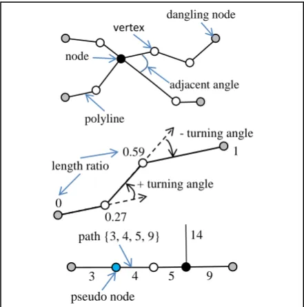
In order to overcome the limit in constructing strokes only by geometric continuation, Yang et al. (2014) devised a pattern graph whose path components are built up through compositing obvious patterns from atomic ones. Both atomic and composite pattern structures are formed and stored in the pattern graphs by capturing and comparing characteristics of feature shapes to preset pattern filters. The pattern filters are based on measures of the metric, geometric, and topological properties. The pattern graph facilitates the navigating along paths and neighbors through the node components (Figure 2). With the basic pattern graph, the dual lines in Figure 1 would simply be identified with the more continuous side in stroke and an ID reference to the other side of the path stored in the path structure.
Figure 2. Path-node structures in pattern graphs (Yang et al. 2014)
vertex dangling node
node
polyline
adjacent angle
- turning angle
+ turning angle
0
1
0.27 0.59 length ratio
path {3, 4, 5, 9}
pseudo node
3 4 5 9
With the pattern recognition filters, small features can be connected by logical reasons, without necessarily satisfying the continuous conditions. For example, as shown in Figure 3, there are four paths, a straight line {7, 8, 9, 10}, a circular lollipop {5, 6}, an L-shape {3, 4}, and a rectangular lollipop {1, 2}. These patterns are formed by the functional purpose to help understand the meaning of data. For example, the pattern group in Figure 3 suggests a part of a residential community.
Figure 3. Pattern paths connected by function
It should be pointed out that while the pattern graph upholds a relatively more descriptive mapping of real world on top of a raw dataset, it is still based on the assumption that all paths are composed of simply connected features. This is evident in the organization of paths as they consist of homogeneous sequential lists of feature IDs, linking to original feature geometries. Without proper extension, it would be awkward for the graph to accommodate more complicated “punctuates” in paths.
2.2 Extended Pattern Graphs
Prior to discussing of the extension, additional needs having been giving rise to from real world are worth investigation. For example, in a layered GIS world, urban road networks may be represented explicitly where road centerlines are captured in a single layer. They may also be represented implicitly through parcel boundaries, or combined where both centerlines and parcel boundaries are presented (Figure 4). While it is likely that the combined representation of road centerlines and parcel boundaries is the result of merging two single layered datasets, the practice indicates a need for the pattern graph to be capable of recognizing and modeling same phenomenon with different expressions.
Figure 4. Road networks expressed differently Data Sources: City of Bangor and Los Angeles County, USA
Figure 4.b illustrates a complex “roundabout” pattern consisting of circular sections formed by dual lines. It is desirable for the pattern graph to recognize and model this pattern and its associated paths from the dataset of Figure 4.b. Similarly for the dataset pictured in Figure 4.c, the same roundabout pattern should be detected. Furthermore, it is important to be able to say that there are two coincident roundabout patterns in the dataset of Figure 4.c, one is from dual boundary paths and the other from centerline paths. Without the pattern structure to group features, sometimes disconnected, it would be difficult to understand relationships between individual features and to match correspondent features from different datasets.
The method of grouping related but not necessarily connected features to form pattern structures relies on spatial reasoning techniques, which are centered at analyzing relationships among neighboring objects. Both quantitative and qualitative analysis, inductive and deductive processes must be considered to reach a scientifically sound conclusion about a hypothesis. For example, without knowing that a linear dataset fits an urban configuration, an analyst would not immediately start the process of finding the roundabout pattern in the data. After analyzing individual features for atomic and composite patterns and having found a full circle which is isolated (disconnected) among other surrounding circular paths, a probing process could start reasoning whether the circle and the surrounding circular paths could together appear to be a cased roundabout pattern.
The search and reasoning process can be shown in Figure 5. In the proximity of the full circle, c, there are other features some of which are identified as circular paths. By comparing the centers and radiuses of the circular paths, only three of them, f, g, and h, are kept for further consideration. The neighbors of both nodes of each circular path are examined to find parallel paths incident to a pair of nodes, respectively. As illustrated in the diagram, parallel paths, p1, p2, incident to nodes n1, n2 are found. Similarly, parallel path pairs, p3, p4, and p5, p6, are identified. At this moment, it is relatively safe to declare that a roundabout out of boundary lines can be formed. In real data, it’s possible that a circular path may not be directly connected to one side of a parallel path pair. Instead, a short circular arc of opposite curvatures may exist in between as a smooth transitive corner. The existence of these transitive arcs makes more sense to the roundabout as required by design to suit smooth traffic flows.
Figure 5. Spatial reasoning for a roundabout structure
The above example suggests disconnected circular paths need to be structured together to form the cased roundabout, consisting of a closed circle and a number of co-centric paths. The extension to the basic pattern graph should possess the mechanism to support both homogeneous and inhomogeneous paths in the same graph such that seamless navigation across the entire pattern graph is guaranteed.
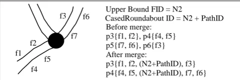
The proposed extension is to add an interpretation about the members, feature IDs, of a path. In the extended graph, the cased roundabout pattern shown in Figure 5 is a path component whose unique ID is the addition of its pathID in the graph and the upper bound value of original feature IDs (Figure 6). 4
3
1 2
5 6
7 8 9 10
a.centerlines b. parcel boundaries c. combined
c f
g
h n1
n2 p1 p2
p3
p4
Figure 6. Extended graph paths
Figure 6 illustrates the effect of the extension, in comparison with what are shown in Figure 5. The paths in Figure 5, p3, p4, p5, and p6, and their composing feature ID lists are exemplified in Figure 6. Before the introduction of the CasedRoundabout pattern and the extension of the pattern graph, it is difficult to understand the relationships between the cased road sections formed by dual paths p3, p4 and p5, p6. With the extension, the recognized CasedRoundabout pattern is a path component in the same graph, which could serve as the connector for a merge of the dual paths. Note that the merged dual strokes p3, p4 contain a punctuate, the CasedRoundabout pattern, whose detail can be retrieved from the PathID, after the deduction of the Upper Bound FID, N2.
3. IDENTIFYING HIERARCHICAL ROAD NETWORKS
3.1 Three Levels of Roads
Among many road types, highways, major roads, and local streets, leveled by traffic speeds, are commonly perceived structures for ground transportation. Ramps are a special type of road between highways and major roads, through which smooth traffic movement is facilitated. Due to the transition nature, ramps will not be treated as a level themselves but be the same as highways in the hierarchy.
3.2 Highways and Ramps
3.2.1 Characteristics of Highways and Ramps
In identifying road hierarchical patterns from road network data, it is of primary useful to firstly recognize highway-ramp structures and then expand the structure to lower levels. A few observations can be made about the highway and ramp data. These characteristics will be used to guide spatial reasoning processes.
Characteristics of highways:
• Have restricted access (entry or exit) through ramps; • Have divided and near parallel lines in opposite
directions;
• There should have no other cross intersections of highways, roads, or ramps at the same elevation level; • Connected lines are usually smooth and long.
Characteristics of ramps:
• Serve as links between highways, major roads, and service stations;
• Highway and ramp meeting at a junction must form a shallow angle;
• Ramps are tends to be shorter.
3.2.2 Strategies for Highway and Ramp Identification There is a practical decision to make in the designing of algorithms aimed at identifying and establishing highway-ramp structures from a line network graph: primarily looking for
highways and finding associated ramps as a side result, or the other way around. Based on the experiments, the late approach is adopted, i.e., primarily looking for ramps in which section of highways or major roads incident to their end nodes will be identified and pieced together considering connection constraints. This is because, without the knowledge of ramps, identifying highway sections and piecing them together as a completed whole is opt to erroneous results, for wrong paths with better continuity parameters could be pieced together.
Real world ramp data may come in various shapes and configurations. While it is true that quite a lot of them are in the form of circular paths, it is not uncommon for them to be in other shapes. This observation renders some efficiency consideration for the process of finding ramp candidates from paths. Excluding large number of unlikely paths with quick decisions would contribute to faster performance of the process. As a matter of fact, considering the shapes of paths, the only restriction that could lead to rejecting a candidate from further computing is that it should never have sharp turns along the path.
Incident paths at both end nodes of a ramp candidate will then be examined. The turn angles on both ends, formed by the tangent extension of the candidate ramp and other incident paths will be used to determine whether the candidate is rejected for being without a single shallow angle on both ends, or accepted for being a ramp and the node types of Exit or Entry. The process of the determination is elaborated with the diagrams and description below. For the sake of continence, it is assumed that the maximum angle, β, at which a ramp can be created for exit traffic is known, and that it is the same as that for entry traffic. Another assumption is, it can be known that the road network is located in North America or other regions of the world. In US, highways are normally entered and exited from right side of the travel direction.
As shown in Figure 7, the incident paths from the nodes F and T of the ramp candidate, R, are found to be (path1, path2, R), (path3, path4, R), respectively. With regard to node F, the tangent extension of R can be computed and its turning angle to path1 is negative and the value is smaller than β. At the moment, it can be said that R is a ramp and its F node is of Entry type. A last analysis will be applied to determine whether path1 and path2 have the same path ID. If they belong to a same path which has already been identified as a highway, R will be attached to the highway with the Entry point properly inserted or appended to the existing junction list. If the IDs of path1 and path2 are not equal but their continuity can be ensured, the two paths will then be merged into one path, say H1. The traffic flow is directed from path1 to path2. At this time, a search for a parallel path to H1 can be performed to determine the type of H1. If a parallel can be found, H1 will be labeled as a divided highway with a dual reference to the parallel. Otherwise, the road type of H1 will be left undetermined at the time. Either case, the ramp R will be recorded in H1 with the F node type. Similarly, the Exit type of the T node of R can be determined and its associated road, H2, is directed from path3 to path4. After both ends are processed and the node types of F and T are known, the undetermined road type at one end can be updated to major road if a highway is determined from the other end. The description about ramp R can now be enriched with junction types and associated highway or major road.
CasedRoundabout ID = N2 + PathID Upper Bound FID = N2
Before merge: p3{f1, f2}, p4{f4, f5} p5{f7, f6}, p6{f3} After merge:
Figure 7. Node type determination
It is not difficult to see that after all qualified ramp are identified, the top level of the road network, highways and ramps, will be identified and topologically connected. Furthermore, the transition of any highways with other highways and major roads is also established.
The general method described above covers a most common and ideal scenario. There are many other highway-ramp-road relations. Real world road data with bizarre geometries and digitizing errors will also require additional considerations and reasoning to make proper identification of ramps, to highlight data errors, or to derive new knowledge about the transportation data. Some of the cases are illustrated in Figure 8, with the additional explanations about the highway-ramp identification process below.
1. If no turning angle smaller than β can be found with any other incident roads at either end node, as shown in Figure 8.a, the candidate R is immediately rejected for further processing.
2. Features near the data boundary may be chopped so nodes become pseudo (connect to exactly 2 paths). As is shown in Figure 8.b, the extension from path1 need to be made at F to help determining the end type of a ramp candidate.
3. When a turning angle of the ramp with any incident path is greater than β, the node in question is a RampStop junction, and the incident paths will all be labeled as major road. Figure 8.c illustrates this case where node T is of the RampStop type, and paths 5, 6 and 3 (merged from path3 and 4) will be labeled as major road.
4. If a ramp candidate is tangent to a path from which a parallel path can also be found. There is, however, additional incident path with a turning angle larger than β (Figure 8.d). It is likely that the additional short path between the parallels is a restricted cross for highway services.
5. Considering the case in Figure 8.e, similar to Figure 8.d, with a difference that the additional path crosses the parallels. It is likely that the intersection is caused by digitizing error. The crossing path may be an overpass or underpass.
6. If a ramp is tangent to a path in one end and has one adjacent path which is routed back to the same tangent path. The node connecting the two ramp candidates may be the location of a service station (Figure 8.f).
Figure 8. Other node types
3.2.3 The Algorithms
The pseudo code below shows the procedural steps for the algorithm described above.
Algorithm 1: Finding Ramps and Highways
Given: A linear dataset.
Output: A road network graph with highways and ramps identified.
Step 1. Build a line network graph, LN, for the given linear dataset, this includes piecing together line segments and recognizing pattern structures;
Step 2. For each smooth path, named path I, in LN, that has not been identified as a road component, call GetConnectRoads which returns
a. the ramp type;
b. road path ID connecting with the from node; and c. road path ID connecting with the to node. Step 3. If returned ramp type is either RampEntry |
RampExit, RampEntry | RampStop, RampExit | RampStop, RampEntry | RampTerminal, or RampExit | RampTerminal, label path I as Ramp and record the returned roads (IDs) with the ramp.
Step 4. Repeat 2 and 3 until all paths in LN processed.
Algorithm 2: Get Connected Roads
Given: A path ID.
Output: path IDs at the both ends of the given path.
Step 1, Get the path data from the path ID;
Step 2. Call DetermineRampEndType for the F end, which returns
a. ramp end type (RampEntry, RampExit, RampStop, or RampTerminal);
b. path ID connected to the ramp end.
Step 3. If the ramp end type is RampEntry or RampExit, search for the path which is parallel to the tangent path returned from the previous step. If such a parallel path is found, perform Step 4. Otherwise, perform Step 5.
Step 4. Extend both the tangent path and the parallel path, which returns two lists of feature IDs composing the two paths. The orientation of the tangent path is in accordance to the ramp end type, and the orientation of the parallel path is opposite. At the same time, the duality of the parallels is recorded by cross-referencing. In the process of extending highway paths, merging to existing highway paths may be done during which housekeeping is needed to update references in all connected highways and ramps.
Step5. Repeat steps 2 to 3 for the T end. junction with 3 roads
Algorithm 3. Determine Ramp End Type
Given: an end node of a path and the path ID. Output: ramp end type and the connected path ID
Step 1, Find all paths incident to the end node, excluding the given path;
Step 2. Compute the end type based on the principle and reasoning described in 3.2;
Step 3. Report the ramp end type and the connected path if any.
3.3 Major and Minor Roads
3.3.1 Characteristics of Major and Minor Roads
Unlike highways, which can be distinguished by their connection to ramps, the separation of major and minor roads are more subtle especially when major roads are not directly connected to ramps. The junctions of both types of roads fall in the same kind of intersection style of “T”, “+”, “X”, or “Y” shapes. Nevertheless, different characteristics of major and minor roads can still be observed from experience, which could be used for making a distinction of the two groups in automated procedures.
Characteristics of major roads:
• Connect to highways through ramps; • Tend to be longer;
• Prevail through a number of junctions with varying distances in between;
• Span more than one clusters of shorter roads; and • Surround clustered communities with other major
roads.
Characteristics of minor roads:
• Branch from major roads, like the vertical bars in “T” junctions;
• Tend to be shorter;
• Be neighbor to other similar roads in a patterned cluster;
• Surrounded by either space or roads; and
• Usually connect to major roads by a small number of in-out roads.
3.3.2 Quantitative Classification
It can be seen that most of the characteristics are of quantitative nature such as lengths of roads, number of junctions, distances between neighbors, and spacing distances for clusters. Distinct numerical ranges are needed to classify roads into correspondent categories. It is proposed in this paper to apply the 1/20/80 principle findings (Jiang 2007, 2009) in determining these threshold values. For example, after highways, ramps, and some of the major roads are labeled through the process described in the previous sections, the remaining unidentified paths can be sorted in descending order of path lengths. The top 20% of the roads by the length measure could be tentatively classified as major roads, and the rest 80% as minor roads. This principle can also be applied to other quantitative measures such as the number of junctions. It is also of interesting to experiment the result of combining the two measures into one, for instance, by sorting the roads in order of their length values multiplying their respective number of junctions.
Another method, proposed by Marshall (2016), applies the “cardinality” property associated with individual roads to determine hierarchical levels of roads. The cardinality of a road equals one more than the highest cardinality values that yield to it. If a road does not have any roads yielding to it, it has a cardinality of 1. The cardinalities, therefore, can be computed
progressively from shortest roads up, increasing the cardinality of the superior road it joints to, if the cardinality of the superior road equals to that of the road in concern. The cardinality concept is relatively new and its practical usefulness needs to be assessed.
3.3.3 Qualitative Determination
Whenever possible, if the level of a road can be determined qualitatively through spatial reasoning, the decision should take higher precedence. It is therefore important to develop qualitative measures through analyzing neighborhood and topological patterns.
Minor roads serve local communities and they lead to households. In urban cores, minor road meshes often form grid patterns, while in modern suburb areas, they tend to be in regular or irregular clusters of rectangular or curved patterns with traffic terminated to dangling roads or cul-de-sacs. It is interesting to note the evolution of road patterns with usage and design style changes (Figure 9).
Figure 9. Evolution of street patterns (Southworth and Ben-Joseph 1997)
Algorithms for discovering some of the crossroad patterns have been published in literature. For example, Heinzle et al. (2007) discussed “ladder” and “comb” pattern structures and entailed an algorithm for recognizing “grid” patterns (Figure 10).
Figure 10. Local road patterns (adapted from Heinzle et al. 2007)
The general approach in discovering local road patterns is, keeping a target pattern in perspective, starting from a most characteristic feature and expanding searches from immediate neighbors out for candidates that satisfy set conditions. For instance, to target a ladder pattern, there most exist a series of similar straight lines, ladder steps, connected to a common line, a ladder bar, with T-intersects. When the ladder steps are stopped by differently connected straight lines, the search is led to find the other ladder bar at the opposite side of the known bar. It is possible that the search ends up with the target pattern, or different patterns, as shown in (Figure 11).
Figure 11. Resultant patterns started from ladder search
Ladder Comb Culs-de-sac
4. EXPERIMENT AND PRELIMINARY RESULTS The initial experiment has been focused on implementing the algorithms for recognizing and assembling highways and connected major roads through identifying ramps. The proof of the concept was done using small data snips that contain ramps and highways. The experiment did not require preprocessing of data with errors such as having gaps in highways; nodes of ramps do not intersect at highway vertices, etc. Additional processing has been added to address some of the issues. Minor changes have also been made in orders that certain processes are executed. After perfect results was achieved with the snips, whole test datasets were processed, which produced expected satisfying results.
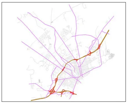
Figure 12 illustrates identified ramps (red), highways (yellow), and some of the major roads (purple). The major roads are connected to ramps or crossing highways and ramp. The faint gray lines, most of them local streets, are also processed but failed to be accepted as ramps, highways, or major roads, by the ramp based identification method. Their identification will be further researched and experimented by incorporating the discussion in 3.3.
It can be observed from Figure 12 that when highways are present as distinctive features in a dataset, the proposed method based on ramp analysis can capture the structures that match perception. The method would have not achieved such results without the presence of highways, as one can image. The quantitative and neighborhood pattern analysis methods would play an essential role in that case. The importance measures, however, must be further investigated as the count of path elements based on the pattern graphs is expectedly much smaller compared with the methods that are not equipped with pattern recognition techniques.
Figure 12. Experiment result of road network structures Data source: City of Bangor, Maine, USA
As was discussed in 3.2 that the spatial reasoning embedded in the proposed method is able to discover data errors or to derive new knowledge, the result in Figure 13 would support the point.
Figure 13. Knowledge discovery through spatial reasoning Data source: HERE
In Figure 13, one type of data errors is: missing intersections of some ramps with highways. Because of this error, the expected node-incident paths relations will be missing in the graph. To avoid incorrect computing, neighbors of dangling nodes are searched and analyzed. In the presence of divided highways among the neighbors, the ramp-highway relation will be determined as if an intersection exists.
Another type of data errors is: the addition of intersections of highways with roads nearly vertical to them. This error can be discovered as divided highways are found and extended, or when major roads are identified by intersecting with highways. The reasoning to avoid this error will be based on strong confidence on the identification of divided highways and the assumption that no roads should be intersecting with highways at near right angles. It can be further derived that the existence of roads by a highway might suggest some thin barriers, like walls, exist between the highway and residence communities; or the highway is elevated.
5. SUMMARY AND FUTURE WORK
A method of constructing hierarchical urban road network is proposed in this paper. When presented in network data, ramps are firstly identified as a crucial component to recognize and assemble highways and sometimes major roads. The paper discussed characteristics of ramps and three levels of roads and how these characteristics can be considered in designing algorithms for their identification. Prototyping implementation of the algorithms and the results obtained from running the prototype demonstrated expected proof of the concept. The method is robust to possible data errors and can be helpful in knowledge discovery, in addition to the targeted objectives.
There are a few more things need to be done to complete the investigation on the method:
Firstly the implementation of the algorithms should be tested on a wide selection of road data. The assumption of exiting and entering highways from right side in the US needs to be safeguarded by handling exceptions that are left-sided.
classification and that of induced from spatial reasoning and analysis on patterns is worth being looked at. This could include the comparison between applying length and junctions and the “cardinality” property for the numerical domains.
Thirdly, the method should also consider the persistence of the discovery with geospatial databases such that the output could support intelligent queries and advanced analysis and simulations with enriched network data.
ACKNOWLEDGMENTS AND DISCLAMATION The author appreciates the support from members in the Esri Geoprocessing team.
Thank you, Dept. of Public Work, Los Angeles County, USA for the sample parcel data; City of Bangor, Maine, USA and HERE for providing the sample road data.
This paper discussed an ongoing research. The author is solely responsible for any errors. The content should not be interpreted as any commitment by Esri to provide specific capabilities in future software releases.
REFERENCES
Baella B, Lee D, Lleopart A, Pla M (2014) ICGC MRDB for topographic data: first steps in the implementation, The 17th ICA Generalization Workshop, 2014, Vienna, Austria.
Heinzle, F, Ander. K. H, Sester, M. 2005. Graph based approaches for recognition of patterns and implicit information in road networks. In: Proceedings of 22nd International Cartographic Conference, A Coruna, Spain.
Heinzle, F, Ander. K. H, Sester, M. 2006. Pattern recognition in road networks on the example of circular road detection. In: M. Raubal, H.J. Miller, A.U. Frank, M.F.Goodchild (Eds.): Geographic Information Science, Münster, Germany, LNCS 4197, pp. 253-267.
Heinzle, F, K.-H. Anders, and M. Sester. 2007. Automatic detection of patterns in road networks – methods and evaluations. Proceedings of Joint Workshop Visualization and Exploration of Geospatial Data, Stuttgart, vol. XXXVI-4/W45 (CD-ROM).
Jiang B. and Claramunt, C. 2004. A structural approach to model generalisation of an urban street network. Geoinformatica: an International Journal on Advances of Computer Science for Geographic Information Systems, 8(2), pp. 157-171.
Jiang B. 2007. A topological pattern of urban street networks: universality and peculiarity. Physica A: Statistical Mechanics and its Applications, 384, 647 – 655.
Jiang B. 2009. Street hierarchies: a minority of streets account for a majority of traffic flow, International Journal of Geographical Information Science, 23(8), 1033-1048, Preprint, arxiv.org/abs/0802.1284.
Lee D., W. Yang, and N. Ahmed. 2014. Conflation in geoprocessing framework – case studies. Proceedings of GEOProcessing, March 2014, Barcelona, Spain.
Marshall S. 2016. Line structure representation for road network analysis. In press: The Journal of Transport and Land Use, 9.1, 2016, pp. 1-38. Downloaded 11/21/2015 from https://www.jtlu.org/index.php/jtlu/article/view/744/695.
Porta, S., P. Crucitti, V. Latora. 2004. The network analysis of urban streets: A dual approach. arXiv:cond-mat/0411241v1.
Porta, S., P. Crucitti, V. Latora. 2006. The network analysis of urban streets: A primal approach. Environment and Planning B: Planning and Design 2006, vol. 33, pp. 705-725.
Southworth, M. and E. Ben-Joseph. 1997. Streets and the Shaping of Towns and Cities. New York: McGraw-Hill. Source:
http://www.cmhc-schl.gc.ca/publications/en/rh-pr/tech/socio75.html.
Thomson, R. and D. Richardson, 1999. The ’good continuation’ principle of perceptual organization applied to the generalization of road networks. In: Proceedings of the ICA, Ottawa, Canada, Session 47B.