DEVELOPING VERIFICATION SYSTEMS FOR BUILDING INFORMATION MODELS OF HERITAGE BUILDINGS WITH HETEROGENEOUS DATASETS
L. Chow ab, S. Fai ab
a Azrieli School of Architecture and Urbanism, Carleton University, 1125 Colonel by Drive, Ottawa, Canada K1S5B6
b Carleton Immersive Media Studio, Carleton University [email protected]
KEYWORDS: building information modelling, verification of data, heterogeneous dataset, heritage documentation.
ABSTRACT:
The digitization and abstraction of existing buildings into building information models requires the translation of heterogeneous datasets that may include CAD, technical reports, historic texts, archival drawings, terrestrial laser scanning, and photogrammetry into model elements. In this paper, we discuss a project undertaken by the Carleton Immersive Media Studio (CIMS) that explored the synthesis of heterogeneous datasets for the development of a building information model (BIM) for one of Canada’s most significant heritage assets — the Centre Block of the Parliament Hill National Historic Site. The scope of the project included the development of an as-found model of the century-old, six-story building in anticipation of specific model uses for an extensive rehabilitation program. The as-found Centre Block model was developed in Revit using primarily point cloud data from terrestrial laser scanning. The data was captured by CIMS in partnership with Heritage Conservation Services (HCS), Public Services and Procurement Canada (PSPC), using a Leica C10 and P40 (exterior and large interior spaces) and a Faro Focus (small to mid-sized interior spaces). Secondary sources such as archival drawings, photographs, and technical reports were referenced in cases where point cloud data was not available. As a result of working with heterogeneous data sets, a verification system was introduced in order to communicate to model users/viewers the source of information for each building element within the model.
1. INTRODUCTION
1.1 Context
Centre Block is the central building of the Parliament Hill National Historic Site in Ottawa, Canada. Designed in the Gothic Revival style by architects Jean Omer Marchand and John A. Pearson, following a fire that destroyed the original Centre Block in 1916, it is a symbol of Canada’s colonial heritage. Construction of the six-storey building and iconic ninety-two meter Peace Tower took nearly a decade to complete. The Centre Block is home to Canada’s parliamentary democracy — housing both the elected House of Commons and the appointed Senate.
In 1986, Centre Block was designated as a Classified Federal Heritage Building for its significance as a national landmark and for its architectural value. According to the Federal Heritage Building Review Office (FHBRO)Heritage Character Impact Statement, the character-defining elements include, “the conception as a symbol of Canada, the whole of its exterior, its many public interiors and its ceremonial circulation spaces, which are inextricably entwined with its symbolic and practical functions as the seat of government, and thus embody its
heritage character; its function as an example of the design methodology of the École des Beaux Arts applied to a Gothic design vocabulary; its clear functional layout reinforced by a carefully considered hierarchy of space; the Gothic ornament of the building, and the on-going carving program in the building” (FHBRO, 1987).
The century-old building will undergo a major rehabilitation program commencing in 2018. The upcoming rehabilitation project will be Public Services and Procurement Canada’s (PSPC) largest and most complex rehabilitation project to date (Government of Canada, 2017). The project includes updating mechanical, electrical and plumbing systems, security, and communications technology, as well as restoring masonry, seismic upgrades, stabilizing existing windows, and replacing roofing. Included in the project mandate is the creation of an existing conditions BIM — undertaken by CIMS in association with PSPC. The development of the Centre Block BIM began in the summer of 2015 and it will be used by the architecture, engineering, and construction consultants to design and manage the project.
The International Archives of the Photogrammetry, Remote Sensing and Spatial Information Sciences, Volume XLII-2/W5, 2017 26th International CIPA Symposium 2017, 28 August–01 September 2017, Ottawa, Canada
This contribution has been peer-reviewed.
1.2 Scope of Work
The intention of creating an existing conditions model of the Centre Block was to facilitate an integrated project delivery (IPD) method for the Centre Block Program of Work. According to the American Institute of Architects (AIA), IPD is defined as “a project delivery approach that integrates people, systems, business structures, and practices into a process that collaboratively harnesses the talents and insights of all project participants to optimize project results”(AIA National, 2007). Although not required for IPD, the use of BIM can help facilitate the early collaboration of all project parties — resulting in increased efficiency and the reduction of errors (Kent, Becerik-Gerber, 2010).
In addition to capturing the existing conditions of the building, the model was developed in anticipation of specific model uses that follow industry best practice including, but not limited to, the generation of drawings, site analysis, design coordination, and design authoring.
In order to meet the goals mentioned above, the level of development (LOD) required for each building element category required specification. However, commonly accepted definitions of LOD — like The Level of Development Specification developed in the United States by BIMFORUM were insufficient for Centre Block. The availability of information for in situbuilding elements varied, creating the need to identify levels of geometric detail, non-graphical information, and accuracy. The prescribed Level of Detail, Information, and Accuracy (LODIA) developed by CIMS for the Centre Block BIM is as follows:
Level of Detail (LOD) relating to the graphical representation of model elements:
● LOD 300 for verified exterior geometry (walls, roofs, foundations) and verified structural elements (steel, masonry, concrete)
● LOD 200 for not verified structural elements (steel, masonry, concrete) based on as-built and design drawings.
● LOD 200 for large volume interior spaces (hallways and common spaces, stairwells, elevators, House of Commons, Senate Chamber, Reading and Railway Committee Rooms, etc. are modelled using surveyed benchmark data from terrestrial laser scanning and / photogrammetry.
The Level of Information (LOI) relating to the embedded information within model elements varied greatly depending on existing sources. All information within, or missing from, the model elements is to be field verified and updated.
The Level of Accuracy (LOA) is related to the deviation found in model elements. The LOA for the Centre Block BIM was determined by comparing the deflection and deviation of the building element to point cloud data. It was determined that any deviations greater than 25mm would be captured within the graphical representation of the building element.
1.3 Data Sources
The Centre Block BIM required the synthesis of heterogeneous data sets. A hierarchy of data was established to help determine which data source had authority/priority over another during the modelling process.
The primary data source was geo-referenced point cloud data from terrestrial laser scanning. The data was captured by CIMS in partnership with Heritage Conservation Services (HCS), PSPC, using a Leica C10 and P40 (exterior and large interior spaces) and a Faro Focus (small to mid-sized interior spaces). Significant heritage interiors including the Senate, Senate Foyer, House of Commons, House of Commons Foyer, Rotunda, Hall of Honour and the exterior of the Peace Tower were also captured by HCS using photogrammetry.
Secondary sources such as archival drawings, photographs, historical steel catalogues, and technical reports were referenced in cases where point cloud data was not available. For example, the structural steel that is normally hidden from view and cannot be captured by laser scanning.
2. VERIFICATION SYSTEM
2.1 Development of Verification System
The scale of the Centre Block BIM and diversity of the data sources required the implementation of a system for communicating the source and verification of individual model elements to a model user/viewer. Our first step in creating the verification system was determining the categories of verifications. We identified three possible levels of verification for model elements: “verified to point cloud”, “not verified to point cloud”, and “partially verified to point cloud”:
● ‘Verified’ model elements were fully modelled in their entirety — including dimensions and placement — from geo-referenced point cloud data. Any model element modelled from point cloud data and deviated less than 25mm could be classified as “Verified to Point Cloud”.
● ‘Not Verified’ model elements were modelled from secondary sources, such as CAD drawings, since point cloud data was not available at the time of modelling.
● ‘Partially Verified’ model elements were modelled in part from geo-referenced point cloud data. In these
The International Archives of the Photogrammetry, Remote Sensing and Spatial Information Sciences, Volume XLII-2/W5, 2017 26th International CIPA Symposium 2017, 28 August–01 September 2017, Ottawa, Canada
This contribution has been peer-reviewed.
instances, point cloud data was available for only some of the geometry and/or the placement of an element. Secondary sources were used to complete the building element. The secondary source was listed beneath the Identity Data in the Properties palette. For example, the placement of a wall acquired from point cloud data, but thickness acquired from HCS CAD drawing (2002).
Two additional verification parameters, “Review Required” and “Placeholder”, were created to communicate to model viewers/users any unusual or unique concerns:
● ‘Review Required’ indicates that a review is required due to insufficient data, misplacement, or clashes with other building elements.
● ‘Placeholder’ model elements were used when the use of standard Revit components was not suitable, or the LODIA was to be increased at a later stage of the project.
2.2 Visualization of Verification System
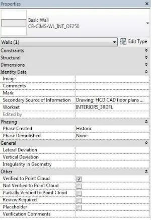
The next step was determining a method in Revit where the verification system could be represented visually in 2D or 3D by colour and within databases such as the model element properties window and schedules. The addition of custom Project Parameters satisfied the above requirements by creating a ‘Yes/No’ verification parameter for all model elements. A ‘Yes/No’ project parameter allows the model users to check/uncheck the appropriate box (Verified, Not Verified, and Partially Verified) within the Properties window of a specific model element as shown in Figure 1.
Figure 1. Properties window showing custom project parameters for the verification system.
Once selected, each element can be sorted and scheduled based upon the verification status as shown in Figure 2. Using Revit’s Filter setting, the verification status can be represented visually through color-coding in schedules and 2D and 3D views. For the Centre Block BIM, model elements were represented in red, green, orange, blue, and purple indicating Not Verified, Verified, Partially Verified, Placeholder, and Review Required respectively — shown in Figure 3.
Figure 2. The verification status of interior walls shown in a wall schedule.
Figure 3. The verification status of interior walls in the Centre Block BIM.
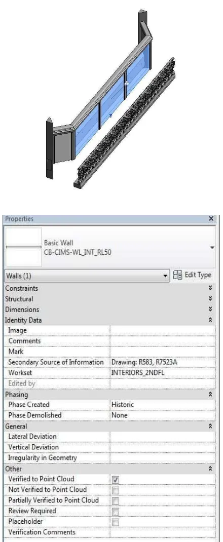
2.3 Secondary Sources of Information
Once the point cloud verifications were created, supplementary verifications were added to effectively communicate the sources of data used to model building elements. A custom Project Parameter — ‘Secondary Source of Information’ — was created as a text parameter for all model elements, however, it was especially critical for model elements classified as ‘Not Verified’. Within the Properties window model users are able to identify any secondary sources of information. Although a building element may be fully verified to point cloud data, the addition of the ‘Secondary Source of Information’ parameter
The International Archives of the Photogrammetry, Remote Sensing and Spatial Information Sciences, Volume XLII-2/W5, 2017 26th International CIPA Symposium 2017, 28 August–01 September 2017, Ottawa, Canada
This contribution has been peer-reviewed.
can list any additional supporting material such as reports or drawings. For example, the balcony railing of the Senate Gallery was modelled from point cloud data but we also used the original 1916 architectural drawings R583 and R7523A to aid in the understanding of its construction. This information was then captured within the element properties as shown in in Figure 4.
Figure 4. Properties window showing custom project parameters indicating secondary sources of information.
3. CONCLUDING REMARKS
Each individual building element within the Centre Block BIM contains the verification parameters that can be viewed by model users in Revit or other BIM software/ model viewers if exported as an .IFC file. In our research, we have determined that the verification of building elements to data sources is not currently an industry standard—especially for the creation of BIM for existing/historic buildings. However, we believe the custom verification system developed by CIMS could greatly enhance the integrity of a model due to the nature of working with heterogeneous data sets.
The verification system resulted in greatly enhanced communication and collaboration efforts amongst team members within CIMS and the project team. For a project as large and complex as the Centre Block BIM, the system not only increased the speed and workflow of the translation of data into building components but also assisted in determining the integrity and accuracy of the model through visual quality control checks.
ACKNOWLEDGEMENTS
CIMS wishes to thank the Parliamentary Precinct Branch, Public Services and Procurement Canada for their ongoing support of our research. Special thanks to Heritage Conservation Services, Real Property Branch, Public Services and Procurement Canada for their technical support.
This project was funded in part by the Social Sciences and Humanities Research Council (SSHRC) of Canada.
REFERENCES
AIA National | AIA California Council, 2007 “Integrated Project Delivery: A Guide – Version 1” https://info.aia.org/SiteObjects/files/IPD_Guide_2007.pdf (May 25, 2017).
BIMForum, 2016. “2016 Level of Development Specification Guide” http://bimforum.org/lod/ (May 26, 2017).
Federal Building Registry Office, 1987 “Heritage Impact Statement: Centre Block”, Ottawa, Ontario, http://www.historicplaces.ca/en/rep-reg/place-lieu.aspx?id=467 5 (June 1, 2017).
Kent, D., Becerik-Gerber, B., 2010. Understanding Construction Industry Experience and Attitudes toward Integrated Project Delivery In: Journal of Construction Engineering and Management, 136(8): pp. 815-825.
The Government of Canada, 2017. “Rehabilitating the Centre Block”https://www.tpsgc-pwgsc.gc.ca/citeparlementaire-parlia mentaryprecinct/rehabilitation/centre-eng.html (June 1, 2017)
The International Archives of the Photogrammetry, Remote Sensing and Spatial Information Sciences, Volume XLII-2/W5, 2017 26th International CIPA Symposium 2017, 28 August–01 September 2017, Ottawa, Canada
This contribution has been peer-reviewed.