A2.1 Introduction
Stress and strain are important concepts in the consideration of both strength and rigidity. They are inevitable and inseparable
consequences of the action of load on a structural material. Stress may be thought of as the agency which resists load; strain is the measure of the deformation which occurs when stress is generated.
The stress in a structural element is the internal force divided by the area of the cross-section on which it acts. Stress is therefore internal force per unit area of cross-section; conversely internal force can be regarded as the accumulated effect of stress.
The strength of a material is measured in terms of the maximum stress which it can withstand – its failure stress. The strength of a structural element is the maximum internal force which it can withstand. This depends on both the strength of the constituent material and the size and shape of its cross-section. The ultimate strength of the element is reached when the stress level exceeds the failure stress of the material.
Several different types of stress can occur in a structural element depending on the
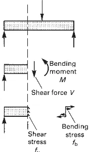
direction of the load which is applied in relation to its principal dimension. If the load is coincident with the principal axis of the element it causes axial internal force and produces axial stress (Fig. A2.1). A load is called a bending-type load if its direction is perpendicular to the principal axis of the element (Fig. A2.2); this produces the internal forces of bending moment and shear force which cause a combination of bending stress and shear stress respectively to act on the cross-sectional planes of the element.
The dimensional change which occurs to a specimen of material as a result of the
application of load is expressed in terms of the dimensionless quantity strain. This is defined as the change in a specified dimension divided by the original value of that dimension. The 134
Stress and strain
Fig. A2.1 Axial load occurs where the line of action of the applied force is coincident with the axis of the structural element. This causes axial stress.
precise nature of strain depends on the type of stress with which it occurs. Axial stress
produces axial strain, which occurs in a
direction parallel to the principal dimension of the element and is defined as the ratio of the change in length which occurs, to the original length of the element (Fig. A2.3). Shear strain, to give another example, is defined in terms of the amount of angular distortion which occurs (Fig. A2.4).
Stress and strain are the quantities by which the mechanical behaviour of materials in response to load is judged. For a given load their magnitudes depend on the sizes of the structural elements concerned and they are therefore key quantities in the determination of element sizes. The size of cross-section must be such that the stress which results from the internal forces caused by the loads is less than the failure or yield stress of the material by an adequate margin. The rigidity is adequate if the deflection of the structure taken as a whole is not excessive.
A2.2 Calculation of axial stress
The axial stress in an element is uniformly distributed across the cross-section (Fig. A2.5) and is calculated from the following equation:
f = P/A
where: f = axial stress
P = axial thrust
A = area of cross-section.
Axial stress can be tensile or compressive. If the size of cross-section does not vary along the length of an element the magnitude of the axial stress is the same at all locations.
A2.3 Calculation of bending stress
Bending stress occurs in an element if the external loads cause bending moment to act on its cross-sections. The magnitude of the bending stress varies within each cross-section from maximum stresses in tension and
compression in the extreme fibres on opposite sides of the cross-section, to a minimum stress in the centre (at the centroid) where the stress changes from compression to tension (Fig. A2.6). It may also vary between cross-sections due to variation in the bending moment along the element.
The magnitude of bending stress at any point in an element depends on four factors,
namely the bending moment at the cross- 135
Fig. A2.3 Axial strain.
Fig. A2.4 Shear strain.
section in which the point is situated, the size of the section, the shape of the cross-section and the location of the point within the cross-section. The relationship between these parameters is
f = My/I
where: f = bending stress at a distance y
from the neutral axis of the cross-section (the axis through the centroid)
M= bending moment at the cross-section
I = the second moment of area of the cross-section about the axis through its centroid; this depends on both the size and the shape of the cross-section.
This relationship allows the bending stress at any level in any element cross-section to be calculated from the bending moment at that
cross-section. It is equivalent to the axial stress formula f = P/A.
The equation stated above is called the elastic bending formula. It is only valid in the elastic range (see Section A2.4). It is one of the most important relationships in the theory of structures and it is used in a variety of forms, in the design calculations of structural
elements which are subjected to bending-type loads. A number of points may be noted in connection with this equation:
1 The property of a beam cross-section on which the relationship between bending moment and bending stress depends is its second moment of area (I) about the particular axis through its centroid which is normal to the plane in which the bending loads lie. This axis is the neutral axis of the beam.
Iis a property of the shape of the cross-section. Its definition is
I=≡y2d
A
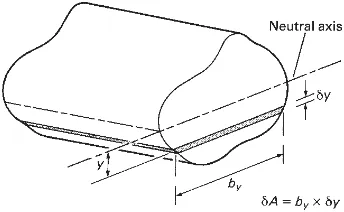
For those who are not mathematically minded Fig. A2.7 may make the meaning of the term more clear. The second moment of area of a cross-section about the axis through its centroid can be evaluated by breaking up the total area into small parts.
136
Fig. A2.6 Distribution of bending stress on a cross-section of an element carrying a bending-type load. (a) Deflected shape. Compressive stress occurs on the inside of the curve (upper half of the cross-section) and tensile stress on the outside of the curve. (b) Cut-away diagram. Shear force and shear stress are not shown.
(a)
(b)
Fig. A2.7 A short length of beam with a cross-section of indeterminate shape is shown here. The contribution which the shaded strip of cross-section makes to the resistance of bending is proportional to ∂I= y2∂
A. The ability of the whole cross-section to resist bending is the sum of the contributions of the elemental areas of the cross-section:
I=⌺y2∂
A
If∂Ais small this becomes:
I=≡y2∂
The second moment of area of any part about the centroidal axis is simply the area of the part multiplied by the square of its distance from the axis. The second moment of area of the whole cross-section is the sum of all of the small second moments of area of the parts.
The reason why this rather strange quantityI, which is concerned with the distribution of the area of the cross-section with respect to its centroidal axis,
determines the bending resistance of the beam is that the size of the contribution which each piece of material within the cross-section makes to the total bending resistance depends on its remoteness from the neutral axis (more precisely on the square of its distance from the neutral axis).
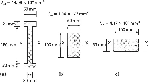
The bending strength of a cross-section therefore depends on the extent to which the material in it is dispersed away from the neutral axis and Iis the measure of this. Fig. A2.8 shows three beam cross-sections, all of the same total area. (a) is stronger in
bending with respect to the X–X axis than (b), which is stronger than (c), despite the fact that the total cross-sectional area of each is the same; this is because (a) has the largestIabout the X–X axis, (b) the next largest and (c) the smallest.
The efficiency of a beam in resisting a bending-type load depends on the
relationship between the second moment of area of its cross-section and its total area of cross-section.Idetermines the bending strength and Athe weight (i.e. the total amount of material present).
2 The elastic bending formula is used to calculate the bending stress at any fibre a distanceyfrom the neural axis of a beam cross-section. The maximum stresses occur at the extreme fibres, where the values of y
are greatest, and, for the purpose of calculating extreme fibre stresses, the equation is frequently written in the form,
fmax=M/Z where:Z =I/ymax
Zis called the modulus of the cross-section. (It is often referred to as the ‘section
modulus’; sometimes the term ‘elastic modulus’ is used and this is unfortunate because it leads to confusion with the term ‘modulus of elasticity’ – see Section A2.4.)
If the cross-section of an element is not symmetrical about the axis through its centroid the maximum stresses in tension and compression are different. Where this occurs two section moduli are quoted for the cross-section, one for each value of ymax.)
3 In the form M=fI/yorM=fZthe elastic bending formula can be used, in
conjunction with a relevant allowable stress value, to calculate the maximum value of bending moment which a beam cross-section can resist. This is called the
‘moment of resistance’ of the cross-section.
4 In the form
Zreq = Mmax/fmax
where: Zreq = modulus of cross-section required for adequate strength
Mmax = bending moment caused by maximum load
fmax = maximum allowable stress
the formula can be used to determine the
size of cross-section required for a particular 137
Fig. A2.8 All of these beam cross-sections have the same area of 5000 mm2but (a) has the greatest bending strength
about the X–X axis because it has the largest Ix–x.
beam. This is an essential stage in element-sizing calculations.
A2.4 Strain
To understand the causes of strain it is
necessary to appreciate how structural material responds when load is applied to it. Its
behaviour is in fact similar to that of a spring (Fig. A2.9).
In the unloaded state it is at rest; it has a particular length and occupies a particular volume. If a compressive load is applied, as in Fig. A2.9, there is at first nothing to resist it; the material in the immediate locality of the load simply deforms under its action and the ends of the element move closer together. This has the effect of generating internal force in the material which resists the load and attempts to return the element to its original length. The magnitude of the resisting force increases as the deformation increases and the movement ceases when sufficient deformation has occurred to generate enough internal force to resist totally the applied load. Equilibrium is then established with the element carrying the load, but only after it has suffered a certain amount of deformation.
The important point here is that the resistance of load can occur only if deformation of material also occurs; a structure can therefore be regarded as
something which is animate and which moves either when a load is applied to it or if the load changes. The need to prevent the movement
from being excessive is a consideration which influences structural design.
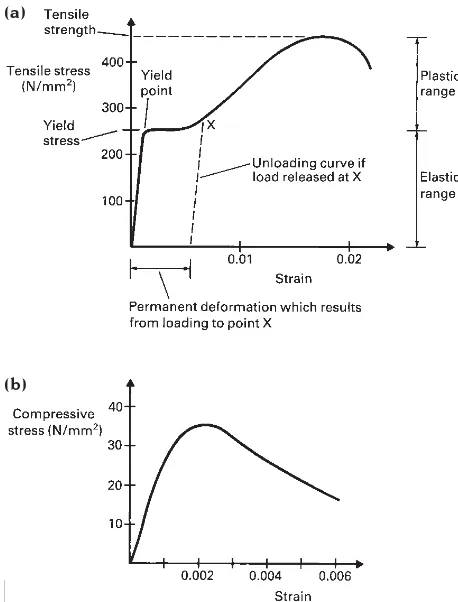
The relationship between stress and strain is one of the fundamental properties of a material. Figure A2.10 shows graphs of axial stress plotted against axial strain for steel and concrete. In both cases the graph is a straight line in the initial stages of loading, the so-called ‘elastic’ range, and a curve in the higher loading range, which is called the ‘inelastic’ or ‘plastic’ range. In the elastic range the stress is directly proportional to the strain and the ratio of stress to strain, which is the gradient of the graph, is constant and is called the ‘modulus of elasticity’ of the material (E).
In the inelastic range the amount of
deformation which occurs for a given increase in load is greater than in the elastic range. A further difference between the two ranges is that if the load is released after the inelastic range has been entered the specimen does not return to its original length: a permanent
138
Fig. A2.9 Deformation following the application of load. The behaviour of a block of material is similar to that of a spring.
Fig. A2.10 Typical graphs of stress against strain for steel and concrete. (a) Steel. (b) Concrete.
(a)
deformation occurs and the material is said to have ‘yielded’. In the case of steel the
transition between elastic and inelastic behaviour occurs at a well-defined level of stress, called the yield stress. Concrete produces a more gradual transition. If a specimen of either material is subjected to a load which increases indefinitely a failure stress is eventually reached; the magnitude of this is usually significantly greater than the yield stress.
The modulus of elasticity is one of the fundamental properties of a material. If it is high, a small amount of deformation only is required to produce a given amount of stress and therefore to resist a given amount of load. Such materials feel hard to the touch; steel and stone are examples. Where the modulus of
elasticity of a material is low the amount of deformation which occurs before a load is resisted is high; this gives the material, rubber for example, a soft feel.
A further point in connection with stress and strain is that the load/deflection graphs for complete structures are similar to the
stress/strain graphs for the materials from which they are made. When the stress in the material in a complete structure is within the elastic range, the load/deflection graph for the structure as a whole is a straight line and the behaviour of the structure is said to be linear. If the material in the structure is stressed in the inelastic range the load/deflection
relationship for the whole structure will not be a straight line and the structure is said to exhibit non-linear behaviour.