Short communication
In
fl
uence of surface roughness on leakage of new metal gasket
Shigeyuki Haruyama
a, Didik Nurhadiyanto
b,c,*, Moch Agus Choiron
d, Ken Kaminishi
a aGraduate School of Innovation and Technology Management, Yamaguchi University, Ube, JapanbDepartment of Mechanical Engineering, Yamaguchi University, Japan
cMechanical Education Engineering Department, Yogyakarta State University, Indonesia dMechanical Engineering Department, Brawijaya University, Indonesia
a r t i c l e
i n f o
Previous studies of new metal gaskets have established that the contact width, contact stress, and simulation process are important design parameters for optimizing the metal gasket performance. Op-timum designs are thus realized based on the elastic and plastic contact stress. However, the influence of theflange surface roughness has not been investigated thoroughly. In this study, we developed a gasket model that includes theflange surface roughness effect. Aflange can have different surface roughness levels. Afinite element method was employed to develop the simulation solution. The contact width, contact stress, and force per unit length for gasket in contact with aflange having different surface roughness levels were obtained through the simulation. The leakage performance improved with an increase in the contact width and contact stress. The slope of the force per unit length increased with a decrease in the surface roughness level. Furthermore, the slope of the force per unit length for a gasket in 400-MPa mode was higher than that for one in 0-MPa mode. The higher slope suggests that the gasket andflange are pressed together strongly. Finally, the helium leakage quantity was determined to evaluate the leakage performance. The experimental result shows that the gasket in 400-MPa mode shows better sealing performance than the gasket in 0-MPa mode. For a low axial force, changes in the surface roughness caused significant changes in the leakage; the same was not observed for a high axial force.
Ó2013 Elsevier Ltd. All rights reserved.
1. Introduction
A new 25A-size metal gasket made of an asbestos substitute was developed. The main advantage of this gasket was that it had a corrugated shape, with a small contact area, that was suitable for realizing low loading; furthermore, the metal spring effect pro-duced a high local contact stress that created a sealing line with the flange [1]. The contact stress and contact width were consider important design parameters for optimizing the gasket perfor-mance. However, the value of the contact width as design has not yet been defined. Haruyama et al. investigated the allowable limits of the contact width[2]. A contact width for which no leakage occurs in the newly developed gasket was determined by comparing the evaluation results of the relationship between the clamping load of theflange and the contact width as obtained using
FEM analysis with the experimental results of the clamping load and the leakage. These results were used to obtain the optimum contact width. The contact width shows a relationship with helium leakage; increasing the contact width results in a decrease the leakage. Choiron et al. [3] studied a method for validating the contact width measurement by using a simulation-based analysis. They compared the simulation result with experimental one ob-tained using pressure-sensitive paper and found good agreement between the two. Persson et al.[4]studied the contact stress dis-tribution. They compared the contact stress distribution result obtained using an analytical model with the (exact) numerical result obtained for contact between a cylinder and a nominalflat substrate with surface roughness having many different length scales and found good agreement between the two. Specially, the theory predicted that the area of contact in most cases varies lin-early with the load and that it depends on the magnification; both predictions showed excellent agreement with the (exact) numeri-cal results. Nurhadiyanto et al. [5] studied the optimization of gasket design based on an elastic and plastic contact stress analysis by considering the forming effect using FEM. A helium leakage test showed that a gasket based on plastic contact stress design was superior to one based on elastic contact stress design. Nonetheless, *Corresponding author. Mechanical Education Engineering Department,
Yogya-karta State University, Indonesia.
E-mail addresses: [email protected] (S. Haruyama), r502wc@ yamaguchi-u.ac.jp (D. Nurhadiyanto), [email protected] (M.A. Choiron), [email protected](K. Kaminishi).
Contents lists available atSciVerse ScienceDirect
International Journal of Pressure Vessels and Piping
j o u r n a l h o m e p a g e : w w w . e l s e v i e r . c o m / l o c a t e / i j p v p
both types of gasket can be used as a seal because they did not show any helium leakage in test.
An important characteristic to consider in the development of a new metal gasket is a function to prevent leakage depending on the surface roughness standard used. Leakage is a function of surface roughness[6]dit increases with the surface roughness. Previous
studies on the design of a new metal gasket used models that did not include the surface roughness effect. The main problem in this regard is the fact that a suitable surface roughness for which no leakage occurs is not yet well understood.
In this light, this study aims to determine the surface roughness of aflange contact that minimizes leakage in the newly developed 25A-size metal gasket. The surface roughness is determined through a comparison between simulation and experimental re-sults. The simulation investigates the contact stress, contact width, and force per unit length according to the surface roughness of the flange. The experiment involves a helium leakage test using two new metal gaskets having different surface roughness levels.
2. Material and methods
2.1. Surface roughness
In practice, all engineering surfaces show some surface rough-ness. When two nominallyflat surfaces are in contact, the actual area of contact is usually only small fraction of the nominal
area-donly the peaks or asperities on the surface are in contactdand
therefore, the real contact stress is higher than the nominal one. When the function of two surfaces is to prevent the leakage of a liquid, this roughness characteristic assumes great importance.
Most engineering surfaces have a surface roughness that lies in a wide range of length scales, and this roughness strongly influences the leakage rate.Fig. 1shows a schematic of how surface roughness leads to imperfect contact between a gasket and aflange. Here, the black and white areas respectively indicate the contacting and non-contacting surfaces. Clearly, thefluid can easilyfind a path through which to percolate, thus causing leakage to occur.
It is difficult to directly analyze the contact between two rough surfaces. Many researchers transform the contact between two rough deformable surfaces into contact between a smooth surface and a rough deformable surface; this is also called as a sum surface
[7e10]. The micro-geometric parameters of each surface are
com-bined to obtain the parameters of the sum surface, as shown in
Fig. 2.
Two contacting rough surfaces are replaced by a single equiva-lent rough surface in contact with a smooth rigidflat surface. The entire asperity contact state after loading is shown in Fig. 3. There are three types of asperities contact states: non-contact asperity, elastic deformed asperity, and plastic deformed asperity.
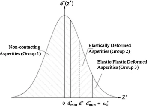
The distribution function of the dimensionless asperity height is described by a dimensionless Gaussian standard probability den-sity function, as shown inFig. 4.
The surfaces of most materials are rough and contain irregular geometric features or asperities with sizes ranging over many length scales. Many models follow the approach proposed by Greenwood and Williamson [11], who chose to idealize a rough surface as a collection of asperities with spherical tips having the same curvature but varying heights. However, their model has proved difficult to apply to surfaces in practice because it is impossible to accurately measure the average curvature of asper-ities on real surfaces. This is because most surfaces have an approximate fractal or self-affine geometry over a wide range of length scales. Gao et al.[12]analyzed in detail the behavior of an elastic-perfectly plastic solid with a sinusoidal rough surface that is subjected to contact loading. Therefore, in this study, we focus upon a sinusoidal rough surface.
2.2. Simulation analysis
A simulation analysis was performed to describe the contact mechanism of the 25A-size metal gasket and the roughflange. By using this approach, the relationship between the surface rough-ness parameter and the contact stress, contact width, and force per
Fig. 1.Schematic of leakage occurring in a gasket pressed against aflange by a uniform pressure distribution.
Fig. 2.Construction of sum surface (adapted from Ref.[9]).
unit length was determined. The gasket used in this study was manufactured using a mold press. It had beads along its circum-ference. When the gasket was tightened to theflange, the beads on both surfaces of gasket created an elastic effect. The flange was assumed to have a rough surface on both sides. The gasket was in contact with both the lower and the upper sides of theflange. The flange pressed the gasket along an axial direction.Fig. 5shows a schematic of gasket tightening in consideration of the surface roughness at the flange and gasket contact area under analysis, where the gasket is shown to have corrugated shape and theflange, aflat shape.
Tightening theflange using bolts can lead to high local contact stress on the convex section of the gasket, realizing a low loading metal gasket, as shown inFig. 6. The contact stress distribution for a corrugated metal gasket is higher than that for aflat metal gasket. This is because the contact stress is distributed in the convex sec-tion. Furthermore, the elastic regions in theflat sections produce the spring effect of metal gasket, and this can be used to reduce the effect caused by the loosening of bolts. Therefore, the new metal is preferred for realizing a low loading metal gasket.
In this study, we analyze aflange having three different surface roughness values: 1.5, 2.5, and 3.5
m
m. According to the explanation above, the surface roughness was modeled as a sinusoidal rough surface. Through the surface roughness measurements, we ob-tained the average roughness (Ra) and the mean spacing of profile irregularities (RSM). Then, both Ra and RSM were used to model the surface roughness of theflange. The average roughness describes height asperities and RSM describes the wavelength of the surface roughness.A flange with the best surface roughness is one that shows minimum leakage. Accordingly, the standard surface roughness for aflange with no leakage can be chosen. It can be denoted by using the slope of the curve of the relationships among the contact width and the axial force, contact stress and axial force, or force per unit length and axial force. The force per unit length was obtained by the product of the average contact stress and the contact width. The slope of the curve increases with a decrease in the axial force. The surface roughness is thus selected based on an increase in the contact width, contact stress, and force per unit length.
In this study, the gasket model was investigated through a forming simulation and a tightening simulation. Fig. 7 shows a flowchart of the various stages of the simulation of the gasket considering the surface roughness effect. These stages were
Fig. 4.Gaussian distribution of asperity heights (adapted from Ref.[10]).
modeled using the MSC’s MARC FEM analysis software[13]. In the first stage, the dies were assumed as rigid bodies on both sides. Using two-dimensional (2D) assumptions, in the axi-symmetric model, a forming process simulation was conducted along the axial direction for the initial gasket material between the top and the bottom of the dies. In the second stage, the gasket shape pro-duced by mold press was continually compressed along the axial direction to tighten the gasket and theflanges. Both the gasket and theflange were assumed as deformable bodies on both sides.
A virtual gasket model with various designs was generated through four basic steps as described in Ref. [5]. Forming and tightening analysis were conducted to obtain the contact stress, contact width, and force per unit length. First, 2-D parameter models of theflange and the gasket were built using Solidwork software. To connect the drawing data obtained from Solidwork (IGES file) and the automatic meshing performed using Hyper-mesh, a batch commandfile was developed, using which a NASfile was generated. We used a uniform quadratic mesh for the gasket material because it has a rectangular section. On the other hand, we used a gradually quadrilateral mesh for the flange because the mesh contains many elements. The procedurefile was configured to perform the pre-processing and run the model on MARC. A graphic user interface (GUI) does not appear; instead, the program runs commands in the background. The output result contains the
contact status, contact width, and contact stress force at each time at every peak position.
2.3. Experimental method
SUS304 was used as the gasket material because of its effec-tiveness in a high-temperature and high-pressure environment. Its material properties werefirst determined through a tensile test carried out based on JISZ2241[14]dthe nominal stress, modulus of
elasticity (E), and tangent modulus were respectively found to be 398.83 [MPa], 210 [GPa], and 1900.53 [MPa].
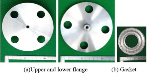
Fig. 8(a) shows a general-purposeflange based on JISB2220[15]
with 10 K pressure and 25A diameter used in this test. The lower flange and the joint were welded carefully to avoid distortions.Fig. 8(b) shows the new 25A-size metal gasket having corrugated shape.
2.3.1. Mold press
The gasket was manufactured using a mold press. The shape of gasket is realized by using a punch to force the initial material to
slide into a die. Hence, the forming effect was considered for assessing the modeling of gasket design. Fig. 9shows the press forming process for manufacturing a gasket.
2.3.2. Surface roughness measurement
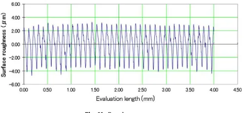
Fig. 10shows the experimental setup of the surface roughness measurement. The surface roughness measurement was based on the JISB0601-2001 standard[16]. All function automatically set the ideal values for the measurement range, evaluation length, cut-off value, and recording magnification according to the measurement conditions. This setup allows the measurement conditions, parameter values, and profile curve data to be directly transmitted to a personal computer. The output result contains the average surface roughness Ra, maximum surface roughness Rz, and another parameter. Furthermore, the output result can be obtained in the form of a roughness curve.Fig. 11shows an example of the surface roughness measurement result. Flanges with three different average surface roughness (Ra) valuesd1.5, 2.5, and 3.5
m
mdwereused.
2.3.3. Leak quantity measurement
To evaluate the axial force and leak quantity, the leakage quantity was measured based on the measurement of that of a helium flow. Fig. 12 shows a schematic diagram of the helium leakage measurement device that was developed for the leakage quantity evaluation test. The helium flow leakage quantity was
quantitatively measured to evaluate the surface roughness of the flange. The highest detection ability in the helium leakage mea-surement was chosen based on the JIS Z2330[17]and JIS Z2331 standard[18]. The measurement method employed is called the vacuum method. First, gas from the test tube and the internal part of the chamber was evaluated using vacuum pumps. The helium gas was injected into the outer part of the gasket in the test chamber and the residual air was measured by using an oxygen density sensor. The helium density could be calculated in the outer part of the gasket.
The helium density was measured when the oxygen density was below 0.2 [%] and the helium density was above 99 [%] under at-mospheric condition. The helium density at the outer part of the gasket was calculated by using a helium leakage detector; in particular, the minimum leakage quantity could be detected. The helium leakage measurement system is built to measure approxi-mately 1.0E 9 Pa m3/s. The minimum and maximum leakage quantity detectable using this device were 1.0 E 11Pa m3/s and approximately 1.0 E 3Pa m3/s, respectively. To avoid the influence of leakageflowfluctuation at the initial stages, measurements were performed between 300 and 500 s. The leakageflow quantity of joint part was calibrated to avoid experimental errors due to the leakage from the joint of theflange and the pipe.
An axial force was produced on theflange by the tightening of theflange using bolts. To approximate the axial force, the tight-ening torque of the bolt is commonly converted into an axial load. Nevertheless, the axial force could not be predicted accurately owing to the different friction coefficients of each bolt and nut used in the clamping as well as the variation of the axial force due to the clamping order of the bolt. To overcome these problems, in this study, the axial force was directly measured by embedding a strain gage into the bolts, as shown inFig. 13. The leakage quantity was
Fig. 9.Forming process.
Fig. 10.Surface roughness measurement setup.
measured based on the measurement of the heliumflow leakage quantity. Axial force levels of 10, 15, 20, 25 and 30 KN were measured for every bolt. The axial force of every bolt was moni-tored in order to adjust the axial force error to below 3%. Four bolts were used to clamp theflange, and therefore, we also tested axial forces of 40, 60, 80, 100, and 100 KN.
In this study, two types of gasketsdelastic (0-MPa mode) and
plastic (400-MPa mode) design [5]dand three flange surface
roughness levelsd1.5, 2.5, and 3.5
m
mdwere investigated.3. Result and discussion
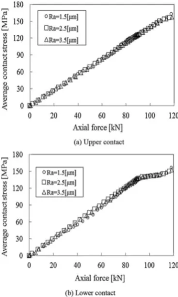
The average contact stress and contact width for peaks 2 and 3 were higher than those for peaks 1 and 4 because the reaction normal force for the former peaks is higher than that for the latter peaks. Thefigure shows that the average contact stress, contact width, and force per unit length were similar for peaks 2 and 3 as well as for peaks 1 and 4. Therefore, we focused our analysis on peaks 2 and 3, which we respectively called as the lower and upper contacts.Fig. 14 shows the simulation result for the upper and lower contacts of a gasket in the 400-MPa mode for the average contact stress. The contact stress for a gasket in contact withflanges having surface roughness values of 1.5, 2.5, and 3.5
m
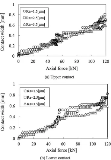
m was similar for both the upper and the lower contacts. Thisfigure shows that the average contact stress increases significantly with the axial force.Fig. 15shows the simulation result for upper and lower contacts of a gasket in the 400-MPa mode for the contact width. Thisfigure shows that the contact width increases with the clamping load.
The contact width in a gasket in contact with aflange having a surface roughness of 3.5 and 1.5
m
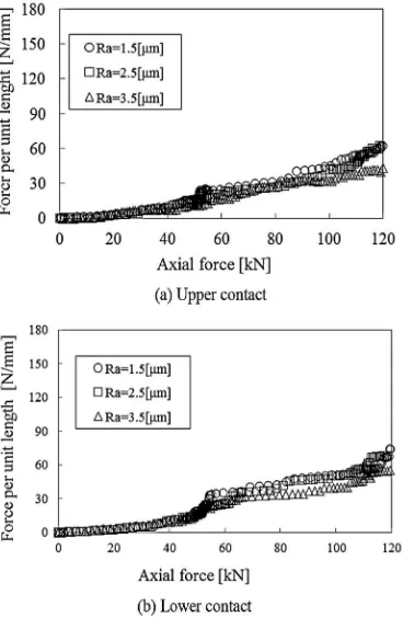
m had the lowest and the highest slope, respectively.Fig. 16 shows the simulation result for the upper and lower contacts for a gasket in 400-MPa mode for the force per unit length. The force per unit length for both contacts was similar. For both contacts, aflange having surface roughness of 3.5
m
m showed the lowest force per unit length. The slope increases significantly for an axial force ofw80 KN for both contacts, indicating a significantincrease in the force per unit length owing to theflange and gasket being pressed together strongly.
Fig. 17shows the simulation results for the upper and lower contact for a gasket in 0-MPa mode for the average contact stress. For both contact, a flange having a surface roughness of 3.5
m
mFig. 13.Measurement of axial force (adapted from Ref.[3]).
Fig. 14.Average contact stress for gasket in 400-MPa mode. Fig. 12.Schematic diagram of helium leakage measurement device (adapted from Ref.
showed the lowest contact stress. The highest slope of the force per unit length was observed for aflange having a surface roughness of 1.5
m
m. For both contacts, the average contact stress between the gasket andflanges having surface roughness value of 1.5, 2.5, and 3.5m
m were similar.Fig. 15.Contact width for gasket in 400-MPa mode.
Fig. 16.Force per unit length for gasket in 400-MPa mode.
Fig. 17.Average contact stress for gasket in 0-MPa mode.
Fig. 18shows the simulation result for the upper and lower contacts for a gasket in 0-MPa mode for the contact width. This figure shows that the contact width increases with the clamping load. The contact width in a gasket in contact with aflange having surface roughness 3.5
m
m and 1.5m
m had the lowest and highest slope, respectively.Fig. 19shows the simulation results for the upper and lower contacts for a gasket in 0-MPa mode for the force per unit length. The force per unit length for both contacts was similar. For both contacts, aflange having a surface roughness of 3.5
m
m and 1.5m
m had the lowest and highest slope of the force per unit length, respectively. The slope increases significantly for an axial force ofw60 KN for both contacts, indicating a significant increase in the
force per unit length owing to theflange and gasket being pressed together strongly.
The simulation results showed that the average contact stress for the gasket in 0-MPa mode was lower than for a gasket in 400-MPa mode. However, the contact width for the former gasket was higher than that for the latter one. Therefore, the force per unit
length of the former gasket was lower than that of the latter one. Consequently, the latter gasket is superior to the former one. The slope of the force per unit length for a flange having a surface roughness of 1.5
m
m is higher than that for roughness values of 2.5 and 3.5m
m for both 400- and 0-MPa mode gaskets. The slope of the force per unit length forflange having a surface roughness of 3.5m
m is the lowest.In the previous study [3], a qualitative explanation obtained using a water pressure test was transformed into a quantitative value using a helium leak test. The quantitative decision criterion for preventing leakage was determined under the condition that the helium leakage quantity was below 1.0 E 6Pa m3/s and it is observed that leakage did not occur in the water pressure test.
Fig. 20shows the result of the helium leakage test for a gasket in 400-MPa mode. A gasket in contact with flange of all roughness levels did not show leakage for a certain axial force. For a low axial force, changes in surface roughness caused significant changes in the leakage; the same was not observed for a high axial force.
Fig. 21shows the result of the helium leakage test for a gasket in 0-MPa mode. A gasket in contact with aflange having a surface roughness of 3.5
m
m showed leakage at all axial force, making this roughness level an unsuitable choice for this gasket. On the other hand, a gasket in contact with aflange having a surface roughness of 1.5 and 2.5m
m did not show leakage for a certain axial force. For a low axial force, changes in surface roughness caused significant changes in the leakage; the same was not observed for a high axial force.Fig. 22shows the relationship between axial force and the he-lium leakage quantity for gaskets with two different modes. For a low axial force, changes in surface roughness caused significant changes in the leakage; the same was not observed for a high axial force. A gasket in 400-MPa mode is superior to one in 0-MPa mode.
Fig. 19.Force per unit length for gasket in 0-MPa mode.
Fig. 20.Leakage measurement result for gasket in 400-MPa mode.
Fig. 21.Leak measurement result for 0-MPa gasket mode.
The slope changes for the former gasket are greater than those for the latter one.
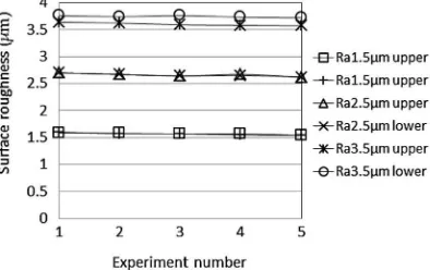
Small changes were observed in the surface roughness after the experiment was completed. Furthermore, theflange was smoother than before after use. Both of these observations are attributable to small deformations that occur during the experiment.Fig. 23shows the changes in surface roughness after the experiment.
A comparison of the simulation results and experimental data showed good agreement, suggesting that the theoretical analysis of the surface roughness is correct and will give accurate prediction. In theory, helium leakage will decrease with an increase in the contact stress and contact width. The force per unit length is given as the Products of the contact stress and contact width. The slope of the force per unit length for a gasket in 400-MPa mode is higher than that for a gasket in 0-MPa mode. Furthermore, the helium leakage test result suggests that the gasket in 400-MPa mode is superior to that in 0-MPa mode.
4. Conclusion
This study investigates the helium leakage quantity for aflange with different surface roughness values through a simulation analysis using FEM and a leakage test. The following conclusions are derived from this study:
1. Simulation results suggest that the average contact stress for a gasket in 0-MPa mode is lower than for one in 400-MPa mode. The contact width for the former gasket was higher than that for the latter one.
2. The average contact stress for aflange having surface rough-ness values of 1.5, 2.5, and 3.5
m
m was similar. The contact width for aflange having a surface roughness of 3.5m
m was the lowest for both types of gasket.3. The force per unit length in the upper and the lower contact was similar. For both contact, a flange having a surface roughness of 3.5
m
m showed the lowest force per unit length. The slope increased significantly for an axial force of 60 andw80 for a gasket in 0-MPa and 400-MPa mode, respectively,
indicating a significant increase in the force per unit length.
However, the force per unit length for the latter gasket was higher than that for the former one.
4. The helium leakage test showed that the gasket in 400-MPa mode showed better sealing performances than the gasket in 0-MPa mode.
5. For a gasket in 0-MPa mode in contact with theflange, leakage occurred for a surface roughness of 3.5
m
m, but not for 2.5 and 1.5m
m, for a certain axial force.6. For a gasket in 400-MPa mode in contact with the flange, leakage did not occur for all surface roughness value for a certain axial force.
7. For a low axial force, changes in surface roughness caused a significant change in the leakage; the same was not observed for a high axial force.
Acknowledgments
This project was supported by the Strength of Material labora-tory, Yamaguchi University, Japan. The second author is grateful for the scholarship support from the Directorate of Higher Education Indonesia in cooperation with Yogyakarta State University.
References
[1] Saeed HA, Izumi S, Sakai S, Haruyama S, Nagawa M, Noda H. Development of new metallic gasket and its optimum design for leakage performance. Journal of Solid Mechanics and Material Engineering 2008;2(1):105e14.
[2] Haruyama S, Choiron MA, Kaminishi K. A study of design standard and performance evaluation on new metallic gasket. In: Proceeding of the 2nd international symposium on digital manufacturing, Wuhan, China 2009. p. 107e13.
[3] Choiron MA, Haruyama S, Kaminishi K. Simulation and experimentation on the contact width of new metal gasket for asbestos substitution. International Journal of Aerospace and Mechanical Engineering 2011;5(4):283e7. [4] Persson BNJ, Bucher F, Chiaia B. Elastic contact between randomly rough
surfaces: comparison of theory with numerical results. Physical Review Let-ters 2002;65:184106.
[5] Nurhadiyanto D, Choiron MA, Haruyama S, Kaminishi K. Optimization of new 25A-size metal gasket design based on contact width considering forming and contact stress effect. International Journal of Mechanical and Aerospace En-gineering 2012;6:343e7.
[6] Widder E. Gaskets: surfacefinish effects in static sealing. ASME B46 Seminar 2004.
[7] O’Callagham M, Cameron MA. Static contact under load between nominally
flat surfaces in which deformation is purely elastic. Wear 1976;36:79e97.
[8] Francis HA. Application of spherical indentation mechanics to reversible and irreversible contact between rough surfaces. Wear 1977;45:221e69. [9] Valloire FR, Paffoni B, Progi R. Load transmission by elastic, elasto-plastic, or
fully plastic deformation of rough interface asperities. Mechanics of Materials 2001;33:617e33.
[10] Kadin Y, Kligerman Y, Etsion I. Unloading an elastic-plastic contact of rough surfaces. Journal of The Mechanics and Physics of Solid 2006;54:2652e74. [11] Greenwood JA, Williamson JPB. Contact of nominally flat surfaces.
Pro-ceedings of the Royal Society of London. Series A 1966;295:300e19. [12] Gao YF, Bower AF, Kim KS, Lev L, Cheng YT. The behavior of an
elastic-perfectly plastic sinusoidal surface under contact loading. Wear 2006:145e54. [13] MSC Marc user manual 2007.
[14] JIS Z2241Method of tensile test for metallic materials. Japanese Standards Association; 1998.
[15] JIS B2220Steel pipeflanges. Japanese Standards Association; 2004. [16] Handysurf E-35A/B user manual 2010.
[17] JIS Z2330Standard recommended guide for the selection of helium leak testing. Japanese Standards Association; 1992.
[18] JIS Z2331Method of helium leak testing. Japanese Standards Association; 2006.
![Fig. 3. Loading completion (adapted from Ref. [10]).](https://thumb-ap.123doks.com/thumbv2/123dok/1221192.685610/2.595.45.285.598.719/fig-loading-completion-adapted-from-ref.webp)