INVESTIGATING INTEGRATION CAPABILITIES BETWEEN IFC AND CITYGML LOD3 FOR 3D CITY MODELLING
G. Floros*, I. Pispidikis and E. Dimopoulou
School of Rural and Surveying Engineering, National Technical University of Athens, 9 Iroon Polytechneiou str., 15780 Zografou, Greece ([email protected]; [email protected]; [email protected])
KEY WORDS: CityGML, IFC, 3D City Model, Data integration, Smart city
ABSTRACT:
Smart cities are applied to an increasing number of application fields. This evolution though urges data collection and integration, hence major issues arise that need to be tackled. One of the most important challenges is the heterogeneity of collected data, especially if those data derive from different standards and vary in terms of geometry, topology and semantics. Another key challenge is the efficient analysis and visualization of spatial data, which due to the complexity of the physical reality in modern world, 2D GIS struggles to cope with. So, in order to facilitate data analysis and enhance the role of smart cities, the 3rd dimension needs to be implemented. Standards such as CityGML and IFC fulfill that necessity but they present major differences in their schemas that render their integration a challenging task. This paper focuses on addressing those differences, examining the up to date research work and investigates an alternative methodology in order to bridge the gap between those Standards. Within this framework, a generic IFC model is generated and converted to a CityGML Model, which is validated and evaluated on its geometrical correctness and semantical coherence. General results as well as future research considerations are presented.
1. INTRODUCTION 1.1 Why 3D City Models?
The generation of complex 3D City Models allows for a more sophisticated understanding of the objects and their spatial interactions with their surrounding environment. The type and amount of information that can be implemented rises drastically, a condition that promotes the necessity of generating semantically enriched 3D Models and highlights the demand for collecting massively huge data. This demand is handled either by (i) the collection of big data, namely a considerable amount of data collected by various sources (Hashem and Anuar, 2016) or (ii) by the knowledge via Internet of Things (IoT), specifically the connectivity of a number of objects to the Internet at an extraordinary rate (Paul et al., 2016). That collected amount of data needs to be properly stored, edited and visualized, issues that GIS science is able to deal with. The massive amount of free data that are available globally, has enhanced the capabilities of addressing critical issues in an integrated and functional way. Hence, GIS is vital for addressing spatial issues and their surrounding context, analyze the proposed solutions and highlight the optimal solution for each scenario in a dynamic environment (Tao, W., et al., 2013). That way, a prominent utilization of a 3D City Model seems mandatory. Semantic 3D city models (Chaturvedi, 2016) join the spatial information with the physical entities in cities and allow an interaction via spatio-semantic queries. They also provide a description of the physical and built environment (Kolbe, 2009). More specifically, 3D models are capable of representing entities such as Buildings, Transportation Networks, elements of a real city such as Bridges, Tunnels and City furniture (Traffic signs, Lights), Vegetation and Water Bodies. Those entities can be semantically enriched with a variety of attributes that vivify a virtual 3D City Model. Furthermore, 3D City Models can be created, edited and visualized in different scales, from basic shapes up to fully detailed both internally and externally real-looking objects. Another significant advantage is the tracking of their life-cycle
* Corresponding author
and the constant monitoring of the project. Within that context, the role of an object is enhanced by adding specific equipment that depends on the project’s purpose. Furthermore, a 3D City Model can be implemented to the environment of a 3D Smart City aiming to integrate descriptive and geographic information in order to enhance its efficiency and sustainability (Batty, et al., 2012) and more specifically in application fields such as transportation, mobility, energy demand, security, urban planning, healthcare and environmental protection.
1.2 3D City Models: Interoperability options
The objective of this paper is to investigate the conversion of a generic IFC Model to a LoD 3 CityGML Model and propose a methodology that generates a model compliant with the prerequisites of the CityGML Standard in terms of geometry validation, topology accuracy and semantic coherence. Section 2 presents a brief overview of the two Standards, as well as the related research work in the field of integration and interoperability. Section 3 describes the methodology and the conversion process in detail, followed by the validation and evaluation of the generated CityGML model. Lastly, Section 4 presents the key findings of the paper and proposes topics of interest for future research work.
2. CityGML & IFC 2.1 Overview of CityGML
CityGML is an open standard that allows the storage and exchange of virtual 3D city models. It does not focus solely on the geometric representation of the objects, but delves into their semantic and thematic properties (OGC, 2012, pp. 9-11). CityGML defines the geometries of the objects, as well as the interactions of each object with the surrounding environment in terms of topology. It represents a variety of thematic city objects such as Buildings, Bridges, Tunnels, Transportation Networks, City Furniture, Vegetation, Land Uses and Water Bodies (Gröger and Plümer, 2012). Each of those objects can be semantically enriched with attributes such as class, function and usage with an input that is supported by the CityGML Standard. Also, CityGML supports 5 Levels of Detail (LoD 0-4), where objects are represented in more detail accordingly to the increasing LoD. Finally, as an open standard it provides the capability of adding extensions (ADEs) based on the requirements and the goals of the 3D Model (OGC, 2012).
2.2 Overview of IFC
IFC is a data format that is used to describe, exchange, share and define how information should be stored throughout the building industry’s life-cycle (El-Mekawy et. al., 2012). It is the international standard for Building Information Modelling (BIM) and is used to create a model of a facility that contains all its information and relationships among its parts and facilitates their sharing among the project members. It can hold data for geometry, quantities, facility management and equipment for various professions. IFC is comprised of a set of schemas and each schema belong to one IFC layer. The content of the schema represents a specific concept of the facility (equipment, geometry, costs). IFC has a full range of geometry classes (solids, surfaces, curves, etc.) and a full range of topology classes (shell, point, path, etc.). Finally, IFC supports the Level of Development (LoD) from 100 up to 500. For the purposes of this paper, the entities investigated were: IFC Building, IFC WallStandardCase, IFC Slab, IFC Window and IFC Door (buildingSMART, 2013).
2.3 Correlation of the two Standards
The interoperability between IFC and CityGML is considered essential since it could address issues such as cost reduction that is also translated in a time-efficient management of projects, advanced data analysis and a unified view of the details of an area (El-Mekawy, 2010). Nagel and Kolbe (2007) and El-Mekawy et al. (2012) highlighted the most relevant relationships in IFC Models that can be applied in geospatial analysis (Fig. 1)
Figure 1: UML Diagram of the most relevant IFC Entities for CityGML (Nagel & Kolbe, 2007)
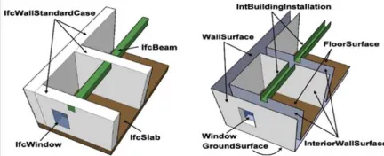
However, the different schemas as well as the handle of geometries and semantics in each Standard renders the integration quite complex. Concretely, IFC focuses on the building environment and provides great detail in terms of structural elements such as Tiles and Walls and equipment such as MEP. On the contrary, CityGML describes the Buildings as observed and used. The differences regarding the semantical objects of a building are pinpointed by Nagel et al. (2009) and highlighted in fig 2. Moreover, IFC focuses solely on the building, while CityGML represents a more complex City Model that is compiled of LandUse, Transportation Objects, Vegetation, Water Bodies, etc. Finally, unlike CityGML, IFC does not support the multi-scale modelling, since its objects are represented in one Level of Detail (Gröger & Plümer, 2012).
Figure 2: Semantics of IFC and CityGML (Nagel, Stadler & Kolbe, 2009)
2.4 State of the art in 3D data integration
geometry and semantics among different objects are highlighted. De Laat and van Berlo (2010) propose a conversion of an IFC model to a LoD 4 CityGML Model via the open-source Building Information Modelserver and address the need of generating lower LoDs by implementing the aforementioned tool.
2.5 Available conversion software tools
There are numerous conversion tools available that convert IFC to CityGML such as BIMserver, KIT IFCExplorer and Feature Manipulation Engine (FME) by Safe Software (Donkers, 2012). BIMserver and IFCExplorer convert successfully the IFC Geometry but lack in semantic mapping (Donkers, 2013). Feature Manipulation Engine (FME) applies Extract Transform Load (ETL) as a two-ways conversion tool (Liu, 2017) and supports the reading of IFC as well as writing in CityGML. The converters from FME that are available up to today, are not capable of converting IFC Models to valid CityGML, even though there is an output in gml format. Various errors such as the geometrical inaccuracy and semantical incoherence of boundary surfaces as structured by CityGML are addressed in the generation of a LoD 2 CityGML model. Additionally, the CityGML output of the conversion in LoD 3 contains thickness in the WallSurfaces, while in LoD 4 both geometries and semantics do not follow the CityGML Standard. However, FME constitutes a fairly flexible and user-friendly tool that handles successfully numerous data formats. This paper aims to properly utilize FME and present a methodology that firstly adjusts the geometry of the model and then regulates the semantics refinement in order to produce a valid LoD 3 CityGML model from a generic IFC model.
3. METHODOLOGY
In order to implement the aforementioned conversion, the IFC generic model was imported in FME Workbench in order to generate the conversion algorithm. The methodology proposed is categorized as follows: Firstly, the geometrical adjustment of the model takes place, in order to be compatible with the CityGML specification for LoD 3 Buildings. Secondly, semantic information based on the CityGML Standard is added and then descriptive information defined by the CityGML Standard is implemented. Afterwards, the generated model is validated in Val3Dity and finally, it is evaluated in terms of complexity. The workflow of the methodology is presented in fig. 3.
Figure 3: Workflow of the methodology
Initially, the model was designed in Autodesk Revit based on architectural plans. Then it was geolocated by linking a CAD georeferenced file of the 2D boundaries of the site, based on the Greek Geodetic Reference 1987 coordinate system. As soon as the modelling process and the geolocation of the model were completed, it was exported to IFC Format 2x3. The IFC entities utilized for the conversion were ΙFC Building, IFC WallStandardCase, IFC Slab, IFC Window and IFC Door. The role of an IFC Building presents similarities with the role of a CityGML Building. The IFC WallStandardCase represents the walls with certain constraints that are extruded vertically and in CityGML is represented with the WallSurface (Building SMART International, 2007). The IFC Slab is a component that encloses a space vertically and servers the role of GroundSurface and RoofSurface in CityGML. Finally, the IFC Door and Window serve the same role as the CityGML Door and Window. The exported IFC model was visualized in FME Data Inspector (Fig. 4) and inserted in FME Workbench.
Figure 4: IFC Model in FME Data Inspector
3.1 Geometrical Adjustment of the model
A key characteristic of an IFC Model is that each surface appears as a solid in contrast with CityGML LoD 3 specification. So, in order to achieve the geometrical adjustment of the model the following process was implemented. The first step of the procedure was to render the IFC geometries compatible with CityGML LoD 3 geometries. More specifically, the interior shell of the building had to be removed. As soon as the exterior shell of the building is extracted, the geometry of the model had to be adjusted, in order to fit the b-rep specification of GML. Therefore, the produced geometries fit the gml: MultiSurface geometry specification of CityGML.
3.1.1 Extraction of geometry: It should be mentioned that each IFC Entity had to be manipulated separately due to the complexity of the schema. The algorithm created for the extraction of the geometry for IFC slab is presented in fig. 5.
Figure 5: Algorithm of extracting IFC Slab
Figure 6: IFC Slab
The algorithm to convert the IFC WallStandardCase (fig. 7) follows the same principles with the IFC Slab at this stage of the process.
Figure 7: IFC WallStandardCase
For the IFC Door, the GeometryExtraction is less complicated, since the model is consisted of only one door. A challenging task is the extraction of the IFC Windows that has to be filtered by attribute characteristics in order to be handled separately on latter stages. Afterwards, the GeometryPart extractor is implemented and the extracted geometry is de-aggregated in order to be converted in a MultiSurface geometry type.
3.1.2 Geometry Refinement: After the phase of the extraction, the geometry should be refined to fit the requirements of CityGML. The part of the algorithm responsible for the refinement of the IFC Slab is presented in fig. 8.
Figure 8: Geometry refinement of IFC Slab
The extracted geometries are inserted in the GeometryCoercer Transformer, which allows the conversion of the geometries in features. The surfaces are converted from Solids to MultiSurfaces. Then, by implementing the AttributeFilter Transformer, the surfaces are categorized based on their attributes to Floor and Roof, which represent the CityGML
GroundSurface and RoofSurface respectively. The same algorithm is applied to the IFC WallStandardCase, IFC Window and IFC Door in order to convert the geometries to MultiSurfaces.
3.2 Semantic Mapping of the Model and Descriptive information
In order to achieve the semantic mapping of the CityGML, the IFC Building is utilized as input and isconverted to CityGML Building. The GeometryRemover transformer is used and then by implementing the AttributeCreator and CityGMLGeometrySetter, the Building is assigned a specific gml_id in order to render its connection with the Boundarysurfaces feasible. For the conversion to a CityGML RoofSurface, the part of the algorithm in fig. 9 is applied. The CityGMLGeometrySetter set the Geometry type to LoD3MultiSurface and the feature role to boundedby. It should be noted at this point, that the aforementioned transformer does not accept as valid input geometries that do not meet the b-rep specifications. The AttributeCreator is used to connect the surfaces with the CityGML Building by matching the gml_parent_id of RoofSurface and GroundSurface with the gml_id of the Building.
Figure 8: Algorithm of semantic mapping of RoofSurface
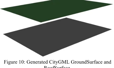
The result produced by CityGML RoofSurface and GroundSurface is demonstrated in fig. 10.
Figure 10: Generated CityGML GroundSurface and RoofSurface.
Figure 11: Algorithm of semantic mapping of Windows
The model is enriched with attributes in accordance with the CityGML Standard, such as gml_name, class, function and usage. This is feasible by utilizing the AttributeCreator Transformer as a final stage of the conversion.
3.3 Validation of the produced CityGML Model
The generated CityGML Model is inserted in the Val3dity software, a validation tool of 3D GML primitives, created by TU Delft in Netherlands. A double inspection is executed with regard to the geometrical accuracy of the model and more specifically to the MultiSurfaces and CompositeSurfaces.
The model is inspected in terms of semantics and also in FZK Viewer. The output is considered satisfactory, since the semantic hierarchy that is structured by CityGML in LoD 3 is preserved (Fig. 12).
Figure 12: Semantic validation of the generated CityGML Model
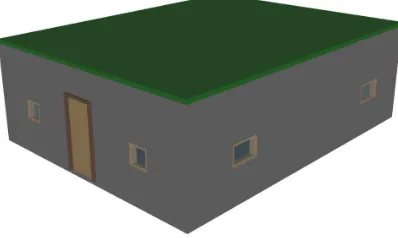
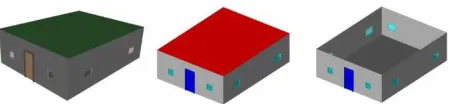
Lastly, the final CityGML Model is visualized in FME Data Inspector, as well as in FZK Viewer (Fig. 13).
Figure 13: Visualisation of the CityGML Model in FME Data Inspector and in FZK Viewer, with and without RoofSurface
3.4 Evaluation of the process
The aforementioned conversion algorithm transforms an IFC generic Model to a LoD3 CityGML Model that is consisted of BoundarySurfaces and Openings (Windows, Doors). However, the following features of CityGML that can be included in a LoD 3 Model were not investigated: Firstly, the model did not include OuterBuildingInstallations. Secondly, there are topological issues that arise during the conversion of a model that shares common boundaries with another model. Furthermore, there are cases of converted building models that are composed of different structural elements that differ in terms of floors or type of roofs and should be implemented as BuildingParts in CityGML. Additionally, the conversion in FME Workbench is a
manual process that must be altered based on the needs of the project. Finally, it should be noted that CityGML Standard follows a specific topological structure. More specifically, each object of the physical space should be represented by one geometrical object. This object should be used as reference from other objects or complicated geometries that are defined and shaped based on that object. In order to implement topology, CityGML utilizes XML Xlinks. However, within the context of the specific paper it is not investigated during the conversion. For example, the generated LoD 3 MultiSurfaces could be utilized for the modelling of the building as LoD3Solid.
4. CONCLUSIONS & FUTURE RESEARCH In terms of results and conclusions it can be stated that the conversion of a generic IFC 2x3 Model to a LoD 3 CityGML Model consisted of Boundary Surfaces and Openings was successful. This paper aims to present a methodology that tackles firstly the geometrical compliance of the Model with CityGML, followed by the semantic mapping and the extension of the model with descriptive information. The generated CityGML Model is validated on the accuracy of the geometry and the concreteness of the semantic hierarchy with positive results. The overall procedure can be characterized as time-efficient and aims to improve the existing converting tools. However, it should be noted that the methodology did not investigate a fully complex LoD 3 CityGML Model and presents certain limitations compared to other methodologies. Nevertheless, this paper constitutes a basis for further research by implementing specific modelling and conversion tools in order to produce valid CityGML models and a holistically methodological approach towards data integration and management that generates, converts and manages a CityGML model in a 3D spatial database.
REFERENCES
Batty, M., Axhausen, W., K., Giannotti, F., Pozdnoukhov, A., Bazzani, A., Wachowicz, M., Ouzounis, G., Portugali, Y., 2012. Smart cities of the future. The European Physical Journal Special Topics, pp. 481-518.
Biljecki, F., Ledoux, H., Du, X., Stoter, J., Soon, K. H. and Khoo, V. H. S., 2016b. The most common geometric and semantic errors in CityGML datasets. ISPRS Annals of the Photogrammetry, Remote Sensing and Spatial Information Sciences, Vol. IV-2/W1, Athens, Greece, pp. 13– 22.
Building SMART International, 2007. Industry Foundation Classes (IFC), IFC2x3. Available from: http://www.buildingsmart- tech.org/specifications/ifc-releases/summary.
De Laat, R., and van Berlo, L., 2011. Integration of BIM and GIS: The development of the CityGML GeoBIM extension. In Advances in 3D Geo-Information Sciences, pp. 211-225. Springer Berlin Heidelberg.
Dimopoulou, E., Tsiliakou, E., Kosti, V., Floros, G., and Labropoulos, T., 2014. Investigating Integration Possibilities between 3D Modeling Techniques. In Proceedings of 9th International 3D GeoInfo Conference, Nov. 2014, Dubai. United Arab Emirates.
Dollner, J., and Hagedorn, B., 2007. Integrating urban GIS, CAD and BIM Data by service-based virtual 3D City models. Urban and regional data management, pp. 157-170.
Donkers, S., Ledoux, H., Zhao, J. and Stoter, J., 2016. Automatic conversion of IFC datasets to geometrically and semantically correct CityGML LOD3 buildings. Transactions in GIS 20(4), pp. 547–569.
Donkers, S., 2013. Automatic generation of CityGML LOD3 building models from IFC models. Master’s thesis, GIS technology group, Delft University of Technology.
El-Mekawy, M., 2010. Integrating BIM and GIS for 3D City Modelling: The Case of IFC and CityGML. Licentiate Thesis, KTH, Stockholm, Sweden.
El-Mekawy, M., Östman, A., and Hijazi, I., 2012. An Evaluation of IFC-CityGML Unidirectional Conversion. International Journal of Advanced Computer Science and Application.
El-Mekawy, M., Östman, A., and Shahzad, K., 2011. Towards interoperating cityGML and IFC building models: a unified model based approach. In Advances in 3D Geo-Information Sciences, pp. 73-93. Springer Berlin Heidelberg.
Eastman, C., M., 1999. Building product models: computer environments, supporting design and construction. CRC press.
Gröger, G., Kolbe, T., and Czerwinski, A., 2007. Candidate OpenGIS® CityGML Implementation Specification (City Geography Markup Language). Open Geospatial Consortium Inc, OGC.
OGC City Geography Markup Language (CityGML) Encoding Standard, 2012. Eds: Gröger, G., Kolbe, T.H., Nagel, C., and Häfele, K.H, Open Geospatial Consortium.
Gröger, G., and Plümer, L., 2012. CityGML – Interoperable semantic 3D city models. ISPRS Journal of Photogrammetry and Remote Sensing 71, pp. 12–33.
Hashem, I., Chang, V., Anuar, N.B., Adewole, K., Yaqoob, I., Gani, A., Ahmed, E., and Chiroma, H., 2016. The role of big data in smart city, International Journal of Information Management, pp. 748-758. https://doi.org/10.1016/j.ijinfomgt.2016.05.002
Isikdag, U., and Zlatanova. S., 2009. Towards Defining a Framework for Automatic Generation of Buildings in CityGML using Building Information Models. In: Lee J. and Zlatanova, S. (Eds.) 3D Geoinformation Sciences, pp.79-96, Springer Berlin Heidelberg.
Kolbe, T.H., 2009. Representing and Exchanging 3D City Models with CityGML. Proceedings of the 3rd International Workshop on 3D Geo-Information, Seoul, Korea. Lectures in Geoinformation and Cartography, Springer Verlag.
Kolbe, T.H., 2008. Representing and Exchanging 3D City Models with CityGML. In: Lee, J., Zlatanova, S. (Eds.), 3D Geo-Information Sciences, pp.15–31. Springer Berlin.
Liu, X., Wang, X., Wright, G., Cheng, J., Li, X. and Liu, R., 2017. A State-of-the-Art Review on the Integration of Building Information Modeling (BIM) and Geographic Information System (GIS). ISPRS International Journal of Geo-Information 6(2), pp. 53.
Nagel, C., Stadler A. and Kolbe Th., 2009a. On the Automatic Reconstruction of Building Information Models from Uninterpreted 3D Models, Academic Track of Geoweb 2009 Conference, Vancouver, Canada.
Nagel, C., Stadler, A. and Kolbe, T. 2009b. Conceptual Requirements for the Automatic Reconstruction of Building Information Models from Uninterpreted 3D Models, Academic Track of Geoweb 2009 Conference, Vancouver.
Nagel C., 2007. Conversion of IFC to CityGML; Meeting of the OGC 3DIM Working Group at OGC TC/PC Meeting, Paris (Frankreich), July 2007.
Rathore, M., M., Ahmad, A., Paul, A., and Rho, S., 2015. Urban palnning and building smart cities based on the Internet of Things using Big Data Analytics. Computer Networks, pp. 63-80. https://doi.org/10.1016/j.comnet.2015.12.023.
Tao, W., 2013. Interdisciplinary urban GIS for smart cities: advancements and opportunities. Geo-spatial Information
Science, pp. 25-34,
http://dx.doi.org/10.1080/10095020.2013.774108.