Informasi Dokumen
- Penulis:
- Yonghong Jiang
- Zhe Chen
- Ping Wu
- Yuanyuan Hu
- Diya Huo
- Jianhao Zhou
- Chengxia Yao
- Jie Bai
- Huaiyi Liu
- Linzhuo Wang
- Huan Zhou
- Pengfei Qi
- Yue Zong
- Chaowei Wang
- Tao Ye
- Zhangwei Qin
- Ying Chen
- Hai Fu
- Xiaolu Wang
- Meng Su
- Mengshi Zhang
- Zhenke Wang
- Fangfang Zhao
- Jiguo Gao
- Li Li
- Yiqing Zhang
- Chao Zhang
- Qian Ma
- Xiaofeng Tu
- Yiming Xu
- Yang Liu
- Edward Chu
- Rick Cheung
- Cher Tse
- Sekolah: Huawei Technologies Co., Ltd.
- Mata Pelajaran: Networking
- Topik: HCNA Networking Study Guide
- Tipe: study guide
- Tahun: 2016
- Kota: Shenzhen
Ringkasan Dokumen
I. Network Communication Fundamentals
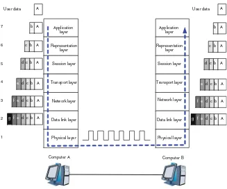
This section provides an overview of the fundamental concepts of network communication, focusing on the principles that underpin how data is transferred across networks. It explores the definitions of communication, the importance of encapsulation and decapsulation, and introduces essential terminology related to network communication.
1.1 Communication and Networks
Communication is the process of conveying information between entities, evolving from traditional methods to modern digital forms. The focus here is on network communication, which involves the transmission of data between computers and devices over various media. Understanding the basic characteristics and terminology of network communication is essential for grasping more complex networking concepts.
1.1.1 What Is Communication?
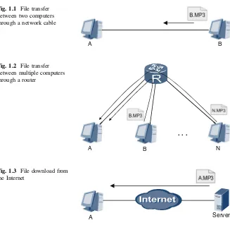
Communication refers to the exchange of information through various media. In network terms, it involves data transfer between computers, facilitated by software that enables file sharing. Understanding this concept is crucial for recognizing how technology enhances human interaction and information exchange.
1.1.2 Courier Deliveries and Network Communications
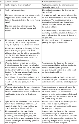
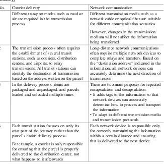
This analogy compares network communication to courier services, illustrating how information is packaged, transmitted, and delivered. By drawing parallels between courier processes and network data transmission, learners can better understand the encapsulation and decapsulation of data, which is vital for effective communication in networks.
1.1.3 Common Terminology
This subsection defines essential terms used in network communication, such as 'data payload' and 'datagram.' Understanding these terms is crucial for comprehending how data is structured and transferred within a network, facilitating clearer communication among network professionals.
1.1.4 Review Questions
Review questions are provided to reinforce understanding of key concepts discussed in this section. These questions encourage learners to apply their knowledge and assess their grasp of network communication fundamentals.
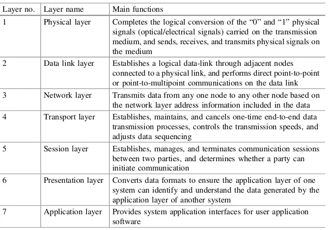
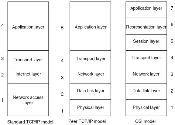
1.2 OSI Model and TCP/IP Model
The OSI and TCP/IP models are foundational frameworks for understanding network communication. This section outlines their definitions, roles, and differences, emphasizing the importance of protocols and layering in facilitating effective communication between diverse network devices.
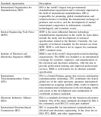
1.2.1 Network Protocols and Standards Organizations
Network protocols are the rules that govern data exchange between devices. This subsection discusses various protocols, including HTTP and TCP, and the role of standards organizations in developing and promoting these protocols to ensure compatibility and interoperability in network communications.
II. VRP Basics
This section introduces the Versatile Routing Platform (VRP), Huawei's network operating system. Understanding VRP is crucial for configuring Huawei devices, as it provides the foundation for managing network operations effectively.
2.1 Introduction to VRP
The VRP serves as the core operating system for Huawei's networking devices. This introduction provides insights into its significance and functionality, laying the groundwork for subsequent sections that delve into command usage and device management.
2.2 VRP Command Lines
This subsection systematically explains the command-line interface of VRP, detailing basic commands and their applications. Mastering these commands is essential for effective device configuration and troubleshooting.
2.3 Logging into a Device
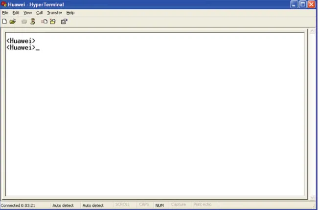
This section covers various methods for logging into Huawei devices, including through console and miniUSB ports. Understanding these processes is fundamental for network administrators managing device configurations.
2.4 Basic Configurations
Basic configurations such as setting host names and IP addresses are crucial for network device management. This section provides step-by-step instructions for performing these essential tasks.
2.5 Configuration File Management
Effective configuration file management is vital for maintaining network device settings. This subsection discusses saving, backing up, and managing configuration files to ensure device reliability and performance.
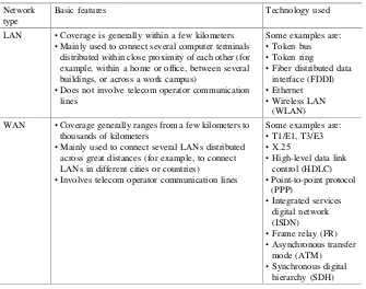
III. Ethernet
Ethernet is a fundamental technology for local area networks (LANs). This section covers its principles, including MAC addresses and frame structures, and provides insights into how Ethernet facilitates data communication.
3.1 Ethernet Cards
This subsection discusses the different types of Ethernet cards used in computers and switches, highlighting their roles in network connectivity and data transmission.
3.2 Ethernet Frames
Understanding Ethernet frames is crucial for grasping how data is packaged for transmission. This section details the structure of Ethernet frames, including MAC addresses and frame formats.
3.3 Ethernet Switches
Ethernet switches play a key role in managing data traffic within a network. This subsection covers their operating principles and how they forward data between devices.
3.4 ARP
The Address Resolution Protocol (ARP) is essential for mapping IP addresses to MAC addresses. This section explains its basic principles and how it facilitates communication within a network.