MOBILE MESSAGING
TECHNOLOGIES AND SERVICES
SMS, EMS and MMS
Second Edition
MOBILE MESSAGING
MOBILE MESSAGING
TECHNOLOGIES AND SERVICES
SMS, EMS and MMS
Second Edition
West Sussex PO19 8SQ, England Telephone (+44) 1243 779777
Email (for orders and customer service enquiries): [email protected] Visit our Home Page on www.wiley.com
All Rights Reserved. No part of this publication may be reproduced, stored in a retrieval system or transmitted in any form or by any means, electronic, mechanical, photocopying, recording, scanning or otherwise, except under the terms of the Copyright, Designs and Patents Act 1988 or under the terms of a licence issued by the Copyright Licensing Agency Ltd, 90 Tottenham Court Road, London W1T 4LP, UK, without the permission in writing of the Publisher. Requests to the Publisher should be addressed to the Permissions Department, John Wiley & Sons Ltd, The Atrium, Southern Gate, Chichester, West Sussex PO19 8SQ, England, or emailed to [email protected], or faxed to (+44) 1243 770620.
Designations used by companies to distinguish their products are often claimed as trademarks. All brand names and product names used in this book are trade names, service marks, trademarks or registered trademarks of their respective owners. The Publisher is not associated with any product or vendor mentioned in this book.
This publication is designed to provide accurate and authoritative information in regard to the subject matter covered. It is sold on the understanding that the Publisher is not engaged in rendering professional services. If professional advice or other expert assistance is required, the services of a competent professional should be sought.
Other Wiley Editorial Offices
John Wiley & Sons Inc., 111 River Street, Hoboken, NJ 07030, USA Jossey-Bass, 989 Market Street, San Francisco, CA 94103-1741, USA Wiley-VCH Verlag GmbH, Boschstr. 12, D-69469 Weinheim, Germany
John Wiley & Sons Australia Ltd, 33 Park Road, Milton, Queensland 4064, Australia
John Wiley & Sons (Asia) Pte Ltd, 2 Clementi Loop #02-01, Jin Xing Distripark, Singapore 129809 John Wiley & Sons Canada Ltd, 22 Worcester Road, Etobicoke, Ontario, Canada M9W 1L1 Wiley also publishes its books in a variety of electronic formats. Some content that appears in print may not be available in electronic books.
British Library Cataloguing in Publication Data
A catalogue record for this book is available from the British Library
ISBN 0-470-01143-2
Contents
Preface . . . xv
About the Author . . . .xvii
Typographic Conventions . . . xix
1 Basic Concepts . . . 1
1.1 Generations of Mobile Communications Networks . . . 1
1.2 Telecommunications Context: Standardization and Regulation . . . 2
1.3 Global System for Mobile Communication. . . 3
1.3.1 Cellular Concept . . . 3
1.3.2 GSM Architecture . . . 4
1.3.3 Mobile Station. . . 4
1.3.4 Base Transceiver Station . . . 6
1.3.5 Base Station Controller . . . 7
1.3.6 Mobile Switching Center and Visitor Location Register . . . 7
1.3.7 Home Location Register . . . 7
1.4 General Packet Radio Service . . . 7
1.4.1 GPRS Architecture . . . 9
1.4.2 Serving GPRS Support Node . . . 9
1.4.3 Gateway GPRS Support Node . . . 9
1.5 Universal Mobile Telecommunications System . . . 9
1.5.1 3G Services. . . 11
1.5.2 First Phase UMTS . . . 12
1.5.3 First Phase UMTS Architecture . . . 13
1.5.4 User Equipment. . . 13
1.5.5 UTRA Network . . . 15
1.5.6 First Phase UMTS Core Network . . . 15
1.5.7 Second Phase UMTS . . . 15
1.6 Wireless Application Protocol . . . 17
1.6.1 Introduction to WAP . . . 17
1.6.2 WAP Architecture. . . 19
1.6.3 Push Technology . . . 20
1.6.4 User Agent Profile . . . 21
1.6.5 WAP 1.x Legacy Configuration . . . 22
1.6.6 WAP HTTP Proxy with Wireless Profiled TCP and HTTP. . . 24
1.6.8 WTP Segmentation and Reassembly . . . 25
1.6.9 OMA Digital Rights Management . . . 27
2 Standardization . . . 29
2.1 Messaging Roadmap . . . 31
2.2 MMS Standards . . . 31
2.3 Third Generation Partnership Project . . . 33
2.3.1 GPP Structure . . . 33
2.3.2 3GPP Specifications: Release, Phase, and Stage . . . 35
2.3.3 3GPP Specifications: Numbering Scheme . . . 35
2.4 Third Generation Partnership Project 2 . . . 37
2.5 GSM Association . . . 37
2.5.1 Working Groups. . . 38
2.5.2 Regional Groups . . . 38
2.6 Internet Engineering Task Force . . . 38
2.6.1 IETF Documents . . . 39
2.6.2 Internet Standard Track . . . 39
2.7 World Wide Web Consortium . . . 40
2.8 WAP Forum . . . 41
2.9 Open Mobile Alliance . . . 42
2.9.1 OMA Organization. . . 43
2.9.2 OMA Specifications . . . 44
2.9.3 Available Documents . . . 45
2.10 Further Reading . . . 46
3 Short Message Service . . . 47
3.1 Service Description . . . 47
3.2 SMS Use Cases. . . 48
3.2.1 Consumer Applications Based on SMS . . . 48
3.2.2 Corporate Applications Based on SMS . . . 50
3.2.3 Operator Applications Based on SMS . . . 50
3.2.4 Value Chain of SMS-Based Applications. . . 51
3.3 Architecture for GSM Networks . . . 51
3.3.1 Short Message Entity . . . 53
3.3.2 Service Center. . . 53
3.3.3 Email Gateway . . . 54
3.4 SMS Basic Features. . . 54
3.4.1 Message Submission and Delivery . . . 54
3.4.2 Status Reports . . . 55
3.4.3 Reply Path . . . 55
3.4.4 Addressing Modes . . . 55
3.4.5 Validity Period. . . 56
3.5 Technical Specification Synopsis . . . 57
3.6 Protocol Layers . . . 57
3.6.2 Message Structure . . . 60
3.6.3 SME-SMSC Transactions: Submit, Deliver, Report, and Command . . . 60
3.7 Structure of a Message Segment . . . 61
3.7.1 Transport Protocol Data Unit . . . 61
3.7.2 Message Types . . . 63
3.7.3 Text Coding Schemes . . . 63
3.7.4 Text Compression. . . 64
3.7.5 Message Classes . . . 64
3.7.6 Coding Groups . . . 64
3.7.7 Protocol Identifiers . . . 65
3.8 Settings and Message Storage in the SIM. . . 65
3.9 Message Submission . . . 69
3.9.1 TPDU Layout . . . 70
3.9.2 TPDU Parameters . . . 70
3.9.3 Rejection of Duplicates . . . 72
3.9.4 Validity Period. . . 72
3.9.5 Absolute Time Representation . . . 74
3.9.6 Destination Address . . . 75
3.9.7 SME Addressing . . . 75
3.10 Message Submission Report . . . 76
3.10.1 Positive Submission Report . . . 77
3.10.2 Negative Submission Report . . . 77
3.10.3 Parameter Indicator . . . 79
3.10.4 Service Center Time Stamp . . . 80
3.11 Message Delivery . . . 80
3.11.1 TPDU Layout . . . 83
3.11.2 TPDU Parameters . . . 83
3.11.3 Status Report Indicator . . . 83
3.11.4 Service Center Time Stamp . . . 83
3.12 Message Delivery Report . . . 84
3.12.1 Positive Delivery Report . . . 86
3.12.2 Negative Delivery Report . . . 87
3.13 Status Report . . . 89
3.13.1 TPDU Layout . . . 90
3.13.2 TPDU Parameters . . . 90
3.13.3 Discharge Time . . . 91
3.14 Command. . . 91
3.14.1 TPDU Layout . . . 95
3.14.2 TPDU Parameters . . . 95
3.15 User Data Header and User Data . . . 95
3.15.1 Information Elements . . . 96
3.15.2 Concatenation of Message Segments . . . 99
3.15.3 Special SMS Message Indication . . . 102
3.15.4 Application Port Addressing . . . 104
3.15.6 User-Data-Header Source Indicator. . . 106
3.15.7 (U)SIM Toolkit Security Header . . . 107
3.15.8 Wireless Control Message Protocol . . . 107
3.15.9 Alternate Reply Address . . . 107
3.15.10 Enhanced Voice Mail Notification . . . 109
3.16 Network Functions for Message Delivery. . . 110
3.17 SMSC Access Protocols . . . 114
3.17.1 SMPP from SMS Forum . . . 114
3.17.2 SMS Open Interface Specification from Sema Group . . . 115
3.17.3 MMAP and SMAP . . . 116
3.18 SIM Application Toolkit . . . 118
3.18.1 Proactive SIM . . . 118
3.18.2 SIM Data Download . . . 119
3.18.3 SIM Interactions: Example . . . 119
3.19 SMS and AT Commands . . . 119
3.19.1 AT Commands in Text Mode . . . 121
3.19.2 AT Command Usage: Example . . . 122
3.20 SMS and Email Interworking . . . 122
3.20.1 Text-Based Method. . . 123
3.20.2 Information Element-Based Method . . . 124
3.21 Index of TPDU parameters . . . 126
3.22 Pros and Cons of SMS. . . 126
3.23 Further Reading . . . 129
4 Enhanced Messaging Service . . . 131
4.1 Service Description . . . 131
4.1.1 Basic EMS . . . 131
4.1.2 Extended EMS. . . 132
4.2 EMS Compatibility with SMS . . . 133
4.3 Basic EMS . . . 133
4.3.1 Formatted Text . . . 133
4.3.2 Pictures . . . 135
4.3.3 Sounds . . . 140
4.3.4 Animations . . . 146
4.3.5 User Prompt Indicator . . . 149
4.3.6 Independent Object Distribution Indicator . . . 152
4.4 Extended EMS . . . 153
4.4.1 Extended Object Framework . . . 154
4.4.2 Extended Object Reuse. . . 158
4.4.3 Compression of Extended Objects . . . 161
4.4.4 Extended Objects . . . 168
4.4.5 Predefined Sounds . . . 169
4.4.6 iMelody . . . 170
4.4.7 Black-and-White Bitmap Picture . . . 171
4.4.9 Color Bitmap Picture . . . 172
4.4.10 Predefined Animation . . . 173
4.4.11 Black-and-White Animation . . . 175
4.4.12 Grayscale Animation . . . 175
4.4.13 Color Animation . . . 177
4.4.14 vCard Data Stream . . . 179
4.4.15 vCalendar Data Stream . . . 183
4.4.16 MIDI Melody . . . 190
4.4.17 Vector Graphics. . . 196
4.4.18 Color for Text Formatting . . . 199
4.4.19 Hyperlink . . . 201
4.4.20 Exchange of Capability Information. . . 202
4.4.21 Guidelines for the Creation of Extended Objects . . . 204
4.5 Pros and Cons of EMS. . . 205
4.6 Further Reading . . . 206
5 Multimedia Messaging Service: Service and Architecture . . . 207
5.1 MMS Success Enablers . . . 208
5.2 Commercial Availability of MMS . . . 209
5.3 MMS Compared with Other Messaging Services . . . 210
5.3.1 SMS and EMS . . . 210
5.3.2 Electronic Mail . . . 210
5.3.3 J-Phone’s Sha-mail and NTT Docomo’s i-shot . . . 211
5.3.4 RIM’s Blackberry . . . 212
5.4 Value Proposition of MMS . . . 213
5.5 Billing Models . . . 214
5.6 Usage Scenarios . . . 215
5.6.1 Person-to-Person Messaging . . . 215
5.6.2 Content-to-Person Messaging . . . 216
5.6.3 Legacy Support and Interworking Between MMS Environments . 217 5.6.4 Further Applications . . . 217
5.7 Architecture . . . 217
5.7.1 MMS Environment . . . 218
5.7.2 MMS Client . . . 218
5.7.3 MMS Center . . . 220
5.7.4 Interfaces . . . 221
5.8 Standardization Roadmap for MMS. . . 222
5.9 WAP Realizations of MMS . . . 223
5.10 Service Features . . . 228
5.11 Message Sending. . . 228
5.12 Message Retrieval . . . 230
5.12.1 Immediate Retrieval . . . 231
5.12.2 Deferred Retrieval . . . 231
5.12.3 Retrieval when Roaming. . . 232
5.13 Message Reports . . . 232
5.22.1 Example of MMS Architecture for the Support of Streaming . . . . 244
5.29.12 3GPP SMIL Profile or PSS SMIL . . . 281
5.29.13 XHTML as an Alternative to SMIL . . . 281
5.30 Example of a Multimedia Message . . . 281
5.31 DRM Protection of Media Objects . . . 281
5.31.1 Forward-Lock . . . 281
5.31.2 Combined Delivery . . . 284
5.31.3 Separate Delivery . . . 284
5.32 Postcard Service . . . 286
5.33 Message Size Measurement . . . 287
5.34 Commercial Solutions and Developer Tools . . . 288
5.35 The Future of MMS . . . 291
5.36 Further Reading . . . 291
6 Multimedia Messaging Service, Transactions Flows . . . 293
6.1 Introduction to the MMS Transaction Model . . . 293
6.1.1 Person-to-Person Scenarios. . . 294
6.1.2 Content-to-Person Scenarios . . . 296
6.1.3 How to Read the PDU Description Tables . . . 297
6.2 MM1 Interface, MMS Client–MMSC . . . 298
6.2.1 Message Submission. . . 301
6.2.2 Message Notification . . . 305
6.2.3 Message Retrieval . . . 314
6.2.4 Delivery Report . . . 319
6.2.5 Read Report . . . 322
6.2.6 Message Forward . . . 324
6.2.7 Storing and Updating a Message in the MMBox . . . 326
6.2.8 Viewing Information from the MMBox . . . 329
6.2.9 Uploading a Message to the MMBox . . . 330
6.2.10 Deleting a Message from the MMBox . . . 333
6.2.11 Parameter Description and Binary Encoding . . . 333
6.3 MM2 Interface, Internal MMSC Interface . . . 340
6.4 MM3 Interface, MMSC–External Servers. . . 346
6.5 MM4 Interface, MMSC–MMSC . . . 346
6.5.1 Introduction to SMTP. . . 349
6.5.2 Routing Forward a Message . . . 352
6.5.3 Routing Forward a Delivery Report . . . 354
6.5.4 Routing Forward a Read Report . . . 357
6.5.5 Example for Message Transfer with SMTP . . . 359
6.6 MM5 Interface, MMSC–HLR . . . 359
6.7 MM6 Interface, MMSC–User Databases . . . 361
6.8 MM7 Interface, MMSC–VAS Applications. . . 361
6.8.1 Introduction to SOAP . . . 363
6.8.2 Message Submission. . . 365
6.8.3 Message Delivery . . . 366
6.8.4 Message Cancellation . . . 369
6.8.6 Delivery Report . . . 371
6.8.7 Read Report . . . 371
6.8.8 Generic Error Handling . . . 373
6.9 MM8 Interface, MMSC–Post-Processing Billing System . . . 375
6.10 MM9 Interface, MMSC–Online Charging System . . . 378
6.11 MM10 Interface, MMSC–Messaging Service Control Function . . . 378
6.12 STI and MMS Transcoding . . . 378
6.12.1 Minor and Major Content Degradations. . . 383
6.12.2 Transcoding Tables . . . 386
6.12.3 Standard Transcoding Interface . . . 387
6.12.4 STI Request Transaction . . . 388
6.12.5 STI Response Transaction . . . 389
6.13 Standard Conformance and Interoperability Testing. . . 389
6.13.1 Static Conformance Requirements . . . 390
6.13.2 Enabler Implementation Conformance Statement. . . 390
6.13.3 Enabler Test Requirements, Plan, and Specification . . . 391
6.13.4 Interoperability Testing. . . 391
6.14 Implementations of Different Versions of the MMS Protocol . . . 392
References . . . 395
Appendices . . . 401
Appendix A SMS TP-PID Value for Telematic Interworking . . . 401
Appendix B SMS–Numeric and Alphanumeric Representations . . . 402
B.1 Integer Representation . . . 402
B.2 Octet Representation . . . 402
B.3 Semi-Octet Representation . . . 403
Appendix C SMS–Character Sets and Transformation Formats . . . 404
C.1 GSM 7-bit Default Alphabet . . . 404
C.2 US-ASCII . . . 406
C.3 Universal Character Set . . . 407
C.4 UCS Transformation Formats. . . 407
Appendix D EMS–iMelody Grammar . . . 408
Appendix E MMS–Content Types of Media Objects. . . 408
Appendix F MM1 Interface–Response Status Codes (X-Mms-Response-Status) . . . 409
Appendix G MM1 Interface–Retrieve Status Codes (X-Mms-Retrieve-Status) . . 412
Appendix H MM1 Interface–MMBox Store Status Codes (X-Mms-Store-Status) . . . 413
Appendix I MM4 Interface–Request Status Codes (X-Mms-Request-Status-Code) . . . 414
Appendix J MM7 Interface–Status Code and Status Text . . . 414
Acronyms and Abbreviations. . . 417
Preface
Is SMS already history? Definitely not if you consider the high SMS traffic volumes of today’s mobile networks! SMS will certainly represent one of the major milestones in the history of mobile telephony. With SMS, users have forged their own dialect to cope with service limitations, composed their own communication groups or communities, and are enjoying new channels of interactions. Any GSM handset has SMS capabilities and if each GSM subscriber sends a message at the same time then more than 1 billion messages would fly over the radio waves of mobile networks worldwide. From an engineering perspective, technologies for SMS have reached a mature stage and no more extensions of SMS are being considered in standardization forums. Much focus is now given to the emerging Multimedia Messaging Service (MMS). The deployment of MMS only started a few years ago and MMS is already gaining wide support from the mobile industry with a fast growing handset penetration rate and worldwide operator support. MMS underlying technologies are still in an ongoing maturation process, and user experience with today’s phones has already greatly improved compared with the one of early implementations. MMS has benefited from the introduction of a new generation of handsets with integrated multimedia capabilities such as color screens and built-in still and video cameras but also from the introduction of packet-based transmission in mobile networks. MMS opens the door to new business opportunities and is believed to be well positioned as the appropriate distribution channel for commercial contents (music downloads, alerts, news, etc.). The future will tell if MMS will follow SMS in becoming a true success story.
The first edition of this book was published in late 2002. It covered SMS, the Enhanced Messaging Service (EMS), and MMS. At that time, SMS was already a very successful service and MMS was emerging. Following the growing interest in MMS, I published a second book dedicated to MMS in late 2003. The second edition of this book builds up from the two previous books. All chapters have been completely revised according to the most recent developments in standardization, but also according to my own experiences, specify-ing embedded messagspecify-ing solutions for a manufacturer of mobile devices and in designspecify-ing MMS solutions for a large group of operators.
dedicated to the Short Message Service. Firstly, it describes major use cases and quickly progresses into the technical details of the service. Chapter 4 focuses on the standard application-level extension of SMS known as the Enhanced Messaging Service. It explains how to create rich-media content and how to distribute this content over SMS as a transport bearer. Chapters 5 and 6 are entirely dedicated to the Multimedia Messaging Service. Chapter 5 explains the service use cases, the overall architecture, and describes how multimedia messages can be designed. Chapter 6 focuses on protocol aspects, presenting the technical realization of each of the MMS interfaces. A set of appendices complement the contents of all chapters and a comprehensive index has been compiled for this book to represent a practical reference companion for solution architects, telecommunication engineers, standardization practitioners, instructors, and students.
I must admit that one of the primary reasons for writing books is that it represented for me a very good opportunity for pretending not to have enough time for washing dishes by hand, hovering the flat, and tidying up my desk. My wife, Marie-Ame´lie, recently discovered the trick and it became a real challenge to finish this book according to the agreed timelines, while being obliged to do the hand-washing of dishes at the same time. We recently purchased a second-hand dish-washer. This really improves our daily living. I have now realized that I do not need to write books anymore to pretend not to have enough time for washing dishes. I may still consider writing articles from time to time, a good reason for pretending not to have the time to clean the table and put dirty dishes in the beloved dish-washer.
I would like to gratefully acknowledge the time and effort of many people who reviewed the content of this book. The book has benefited from constructive comments from experts involved in various MMS activities (standardization bodies, mobile network operators, handset manufacturers, and third party application developers). In particular, I am thankful to Eskil A˚ hlin, Ste´phane Augui, Philippe Bellordre, Luis Carroll, Dave Chen, Franc¸ois Courau, Philippe Delaloy, Cyril Fenard, Peter Freitag, Arthur Gidlow, Pierre Grenaille, Ian Harris, Michael Ishizue, Herve´ Languille, Josef Laumen, Marie-Ame´lie Le Bodic, Arnaud Le Roy, Bernd Mielke, Ngoc Tanh Ly, Je´rome Marcon, Thibaut Mienville, Thomas Picard, Jean-Luc Ricoeur, Friedhelm Rodermund, Andreas Schmidt, Jose´ Soares, Frank Timphus, Fre´de´ric Villain, Paul Vincent, and Wilfried Zeise.
I would also like to acknowledge all readers of the first edition and in particular those who provided feedback. I have used this valuable feedback, whenever possible, to improve the accuracy and readability of this second edition.
The team at John Wiley & Sons, Ltd involved in the production of this book, provided excellent support and guidance. Particularly, I am grateful to Mark Hammond and Sarah Hinton for their continuous support during the entire process.
In addition, I am thankful to Alcatel Business Systems, Bijitec, Siemens AG, and Sony Ericsson for providing illustrations for this book.
The bibliography lists a number of standards that are useful for exploring further topics introduced in this book. Pointers to these standards and other useful resources are available from this book’s companion website at:
http://www.lebodic.net/mms_resources.htm
About the Author
Gwenae¨l Le Bodic is a messaging architect for the Vodafone group, located in Germany. In the scope of his activities for Vodafone, he is involved in the design of messaging solutions for large multi-operator environments. He also contributes to the development of system interworking to enable the exchange of multimedia messages between operators.
Previously, Gwenae¨l Le Bodic was a messaging and standardization expert for Alcatel’s mobile phone division, located in France. His activities for Alcatel included participating and contributing to the development of messaging services and technologies in the scope of the 3GPP and OMA standardization forums. He has been responsible for the design of the software architecture of the embedded multimedia messaging solution for Alcatel’s first two MMS phones.
A certified engineer in computer sciences, Gwenae¨l Le Bodic obtained a PhD in mobile communications from the University of Strathclyde, Glasgow. He is the author of many research publications in the field of mobile communications. He wrote the first edition of this book Mobile Messaging, Technologies and Services (John Wiley & Sons, Ltd, November 2002) and also a book focusing on MMS, Multimedia Messaging Service, an engineering approach to MMS(John Wiley & Sons, Ltd, October 2003).
In this book, the following typographic conventions are used:
Typeface or symbol Meaning/used for Example
Courier Refers to a system command, name
of protocol operation, meta language tag, or any computer output.
The two most common object identifiers that are used are the
Content-IDand the
Content-Location.
<courier> Serves as a placeholder for variable
text that can be replaced as appro-priate in the context of use.
Fields<to-address>and <from-address>can take two
forms. [<courier>] Serves as a placeholder for optional
variable text that can be replaced as appropriate in the context of use.
[<from-address>]
[Times] Refers to a document (e.g., standard,
book, article) listed in the References section.
[3GPP-23.140]
Italic Emphasizes a new word or term of significance.
The application segments the message into several pieces calledmessage segments.
l For description of protocol data
units, this symbol indicates that the corresponding parameter is mandatory.
# For description of protocol data
units, this symbol indicates that the corresponding parameter is optional.
# For description of protocol data
units, this symbol indicates that the corresponding parameter appears conditionally in the unit.
0xA9 Represents a hexadecimal value
prefixed by ‘‘0x.’’
1
Basic Concepts
This chapter outlines the basic concepts of mobile communications systems and presents the required background information necessary for a clear understanding of this book. First, an over-view of the evolution of mobile communications systems is provided. This encompasses the introduction of first generation analog systems supporting only voice communications to the recent deployment of third generation systems supporting voice and multimedia services. The Global System for Mobile Communication, commonly known as GSM, has been a major breakthrough in the domain of mobile communications. Elements composing a typical GSM network are presented. Another important milestone is the introduction of the General Packet Radio Service (GPRS) allowing the support of packet-based communications in evolved GSM networks. The architecture of a GPRS network is presented. Recently deployed are Universal Mobile Telecommunications Systems (UMTS). These systems support advanced multimedia services requiring high data rates. UMTS services and supporting technologies are also introduced in this chapter. Additionally, the Wireless Application Protocol (WAP) is described. WAP is an enabling technology for developing services such as browsing and multimedia messaging. An overview of latest digital rights management methods is also provided. The last section of this chapter provides pointers to books and reference articles for anybody wishing to further explore the topics covered in this chapter.
1.1 Generations of Mobile Communications Networks
In France, in 1956, a very basic mobile telephony network was implemented with vacuum electronic tubes and electron-mechanical logic circuitry. These devices used for wireless communications had to be carried in car boots. In these early days of mobile telephony, service access was far from being ubiquitous and was reserved for a very limited portion of the population. Since the introduction of this experimental network, mobile communications technologies benefited from major breakthroughs commonly categorized in three genera-tions. In the 1980s,first generation (1G) mobile systemsarrived in Nordic countries. These first generation systems were characterized by analog wireless communications and limited support for user mobility.
Digital communications technology was introduced withsecond generation (2G) mobile systemsin the 1990s. Second generation systems are characterized by the provision of better quality voice services available to the mass market. Second generation systems benefited from the cellular concept in which scarce radio resources are used simultaneously by several mobile users without interference. The best known 2G system is the Global System for Mobile Communication (GSM) with the billionth GSM user connected in the first quarter of 2004. Other major 2G systems include cdmaOne (based on CDMA technology), with users in the Americas and Asia, and Japanese Personal Data Cellular (PDC) with the iMode technology for mobile Internet.
Early 2004, first third generation (3G) mobile systems have been deployed in several European countries. With 3G systems, various wireless technologies converge with Internet technologies. Third generation services encompass a wide range of multimedia and cost-effective services with support for worldwide user mobility. The migration to 3G systems is facilitated by the introduction of intermediary evolved 2G systems, also known as 2.5G systems.
1.2 Telecommunications Context: Standardization and Regulation
In the telecommunications environment, Standard Development Organizations (SDOs) provide the necessary framework for the development of standards. These standards are technical documents1 defining or identifying the technologies enabling the realization of telecommunication network technologies and services. The prime objective of SDOs is to develop and maintain widely accepted standards allowing the introduction of attractive services over interoperable networks. The actors that are involved in the standardization process are network operators, manufacturers, and third party organizations such as content providers, equipment testers, and regulatory authorities. One of the main objectives of telecommunications regulation authorities is to ensure that the telecommunications environ-ment is organized in a sufficiently competitive environenviron-ment and that the quality of service offered to subscribers is satisfactory.In the early days of mobile communications, various regional SDOs developed specifica-tions for network technologies and services independently. This led to the development of heterogeneous networks where interoperability was seldom ensured. The lack of interoper-ability of first generation mobile systems prevented the expansion of a global international mobile network that would have certainly greatly improved user experience. With second and third generations systems, major SDOs decided to gather their efforts in order to ensure that mobile communication networks will appropriately interoperate in various regions of the world. In 1998, such an effort was initiated by several SDOs including ARIB (Japan), ETSI (Europe), TTA (Korea), TTC (Japan), and T1 (USA). The initiative was named the Third Generation Partnership Project (3GPP). The 3GPP standardization process is presented in Chapter 2.
1.3 Global System for Mobile Communication
Before the introduction of the Global System for Mobile Communication (GSM), mobile networks implemented in different countries were usually incompatible. This incompatibility made impracticable the roaming of mobile users across international borders. In order to get around this system incompatibility, the Confe´rence Europe´enne des Postes et Te´le´commu-nications (CEPT) created the Groupe Spe´cial Mobile1committee in 1982. The main task of the committee was to standardize a pan-European cellular public communication network in the 900 MHz radio band. In 1989, the European Telecommunications Standard Institute (ETSI) took over the responsibility for the maintenance and evolution of GSM specifications. In 2000, this responsibility was transferred to 3GPP. The initiative was so successful that networks compliant with the GSM standard have now been developed worldwide. Variations of the GSM specification have been standardized for the 1800 and 1900 MHz bands and are known as DCS 1800 and PCS 1900, respectively. In March 2004, the GSM association2 reported a total number of 1046.8 million subscribers distributed over 207 countries.
A GSM network is characterized by digital voice communications and support of low-rate data services. The GSM air interface is based on Time Division Multiple Access (TDMA). With TDMA, a radio band is shared by multiple subscribers by allocating one or more timeslots on given radio carriers to each subscriber. With GSM, the transfer of data can be carried out over circuit-switched connections. For these data communications, bit rates up to 14.4 Kbps can be achieved on single-slot connections. The single-slot configuration is called Circuit Switched Data (CSD). Higher bit rates up to 57.6 Kbps can be attained by allocating more than one slot for a data connection. This multi-slot configuration is called High Speed CSD (HSCSD).
One of the most popular GSM services is the Short Message Service (SMS). This service allows SMS subscribers to exchange short text messages. An in-depth description of this service is provided in Chapter 3. An application-level extension of SMS in the form of the Enhanced Messaging Service (EMS) is presented in Chapter 4.
1.3.1 Cellular Concept
Radio bands available for wireless communications in mobile networks represent very scarce resources. In order to efficiently use these resources, GSM networks are based on thecellular concept. With this concept, the same radio resources (characterized by a frequency band and a timeslot) can be utilized simultaneously by several subscribers without interference if they are separated by a minimum distance. The minimum distance between two subscribers depends on the way radio waves propagate in the environment where the two subscribers are located (e.g., presence of buildings, etc.). In a GSM network, the smaller the cells, the higher is the frequency reuse factor, as shown in Figure 1.1.
In a GSM network, a fixed base station transceiver manages the radio communications for all mobile stations located in a cell. Each geometrical cell in Figure 1.1 represents the radio coverage of one single base station.
1.3.2 GSM Architecture
The main elements of the GSM architecture [3GPP-23.002] are shown in Figure 1.2. The GSM network is composed of three subsystems: the Base Station Subsystem (BSS), the Network Subsystem (NSS), and the Operation Subsystem (OSS). The OSS implements functions that allow the administration of the mobile network. For the sake of clarity, elements of the OSS are not represented in the GSM architecture shown in Figure 1.2. Elements of the BSS and NSS are further described in the following sections.
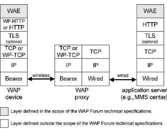
1.3.3 Mobile Station
TheMobile Station(MS) is a device that transmits and receives radio signals within a cell site. A mobile station can be a basic mobile handset, as shown in Figure 1.3, or a more complex Personal Digital Assistant (PDA). Mobile handset capabilities include voice communica-tions, messaging features, and phone book management. In addition to these basic capabilities, a PDA is usually shipped with an Internet microbrowser and an advanced Personal Information Manager (PIM) for managing contacts and calendaring/scheduling entries. When the user is moving (i.e., while driving), network control of MS connections is switched over from cell site to cell site to support MS mobility. This process is called handover.
The mobile station is composed of the Mobile Equipment (ME) and the Subscriber Identity Module(SIM). The uniqueInternational Mobile Equipment Identity(IMEI) stored in the ME identifies uniquely the device when attached to the mobile network.
The SIM is usually provided by the network operator to the subscriber in the form of a smart card. The microchip is often taken out of the smart card and directly inserted into a dedicated slot in the mobile equipment. A SIM microchip is shown in Figure 1.4.
Today’s mobile stations can be connected to an external device such as a PDA or a personal computer. Such an external device is named aTerminal Equipment(TE) in the GSM architecture.
A short message is typically stored in the mobile station. Most handsets have SIM storage capacities. High-end products sometimes complement the SIM storage capacity with
cells are usually yed in rural onments where the
deployed in urban environments where th population density is hi
Large cells are usually deployed in rural environments where the population density is low.
Small cells are usually deployed in urban environments where the population density is high.
Mobile The SIM allows the network to identify the user. The SIM can host an application. The BTS contains the radio transmitters for communicating with Mobile Stations (MS).
The BSC manages the radio resources for one or more BTSs.
administrative information about each registered user.
additional storage in the mobile equipment itself (e.g., flash memory). It is now common to find handsets shipped with a PIM. The PIM is usually implemented as an ME internal feature and enables elements such as calendar entries, memos, phonebook entries, and of course messages to be stored in the ME. These elements are managed, by the subscriber, with a suitable graphical user interface. These PIM elements remain in the PIM even when the SIM is removed from the mobile handset. Alternatively, simple elements such as short messages and phonebook entries can be directly stored in the SIM. A SIM can contain from 10 short messages to 50 short messages on high-end solutions. Storing elements in the SIM allows messages to be retrieved from any handset simply by inserting the SIM in the desired handset. The benefit of storing messages in the ME is that the ME storage capacity is often significantly larger than the SIM storage capacity.
1.3.4 Base Transceiver Station
The Base Transceiver Station(BTS) implements the air communications interface with all active MSs located under its coverage area (cell site). This includes signal modulation/ demodulation, signal equalizing, and error coding. Several BTSs are connected to a single
Figure 1.3 Mobile station handset – reproduced by permission of Alcatel Business Systems
Base Station Controller (BSC). In the United Kingdom, the number of GSM BTSs is estimated around several thousands. Cell radii range from 10 to 200 m for the smallest cells to several kilometers for the largest cells. A BTS is typically capable of handling 20–40 simultaneous communications.
1.3.5 Base Station Controller
The BSC supplies a set of functions for managing connections of BTSs under its control. Functions enable operations such as handover, cell site configuration, management of radio resources, and tuning of BTS radio frequency power levels. In addition, the BSC realizes a first concentration of circuits towards the MSC. In a typical GSM network, the BSC controls over 70 BTSs.
1.3.6 Mobile Switching Center and Visitor Location Register
The Mobile Switching Center(MSC) performs the communications switching functions of the system and is responsible for call set-up, release, and routing. It also provides functions for service billing and for interfacing other networks.
The Visitor Location Register(VLR) contains dynamic information about users who are attached to the mobile network including the user’s geographical location. The VLR is usually integrated to the MSC.
Through the MSC, the mobile network communicates with other networks such as the Public Switched Telephone Network (PSTN), Integrated Services Digital Network (ISDN), Circuit Switched Public Data Network (CSPDN), and Packet Switched Public Data Network (PSPDN).
1.3.7 Home Location Register
TheHome Location Register(HLR) is a network element containing subscription details for each subscriber. An HLR is typically capable of managing information for hundreds of thousands of subscribers.
In a GSM network, signaling is based on the Signaling System Number 7 (SS7) protocol. The use of SS7 is complemented by the use of the Mobile Application Part (MAP) protocol for mobile specific signaling. In particular, MAP is used for the exchange of location and subscriber information between the HLR and other network elements such as the MSC. For each subscriber, the HLR maintains the mapping between the International Mobile Subscriber Identity(IMSI) and theMobile Station ISDN Number (MSISDN).
For security reasons, the IMSI is seldom transmitted over the air interface and is only known within a given GSM network. The IMSI is constructed according to [ITU-E.212] format. Unlike the IMSI, the MSISDN identifies a subscriber outside the GSM network. The MSISDN is constructed according to [ITU-E.164] format (e.g.,þ33612345678 for a French mobile subscriber).
1.4 General Packet Radio Service
allows subscribers to send and receive data over packet-switched connections. The use of GPRS is particularly appropriate for applications with the following characteristics:
bursty transmission (for which the time between successive transmissions greatly exceeds the average transfer delay);
frequent transmission of small volumes of data; infrequent transmission of large volumes of data.
These applications do not usually need to communicate permanently. Consequently, the continuous reservation of resources for realizing a circuit-switched connection does not represent an efficient way to exploit scarce radio resources. The basic concept behind the GPRS packet-based transmission lies in its ability to allow selected applications to share radio resources by allocating radio resources for transmission only when appli-cations have data to transmit. Once the data have been transmitted by an application, radio resources are released for use by other applications. Scarce radio resources are used more efficiently with this mechanism. GPRS allows more radio resources to be allocated to a packet-based connection than to a circuit-switched connection in GSM. Consequently, a packet-based connection usually achieves higher bit rates (up to 171.2 Kbps) by using a multislot configuration for uplinks and downlinks as shown in Table 1.1. For instance, a mobile station of multislot GPRS class 6 can have a maximum of three slots allocated to the downlink and a maximum of two slots allocated to the uplink. However, for such a mobile station, a maximum of four slots only can be active at a time for both uplink and downlink. The capacity of each slot depends on the channel encoding used. Four channel encoding schemes are available in GPRS with distinct levels of error protection and are typically selected according to the quality of the radio environment. GPRS can offer ‘‘always on’’ connections (sending or receiving data at any time).
Table 1.1 Multislot GPRS classes
Multislot GPRS Downlink Uplink Active
class slots slots slots
1 1 1 2
2 2 1 3
3 2 2 3
4 3 1 4
5 2 2 4
6 3 2 4
7 3 3 4
8 4 1 5
9 3 2 5
10 4 2 5
11 4 3 5
1.4.1 GPRS Architecture
The main elements composing the GPRS architecture [3GPP-23.060] are shown in Fig-ure 1.5. A GPRS mobile station is categorized according to its capabilities to support simultaneous modes of operation for GSM and GPRS [3GPP-22.060] which are as follows:
Class A: the mobile station supports simultaneous use of GSM and GPRS services (attachment, activation, monitoring, transmission, etc.). A class A mobile station may establish or receive calls on the two services simultaneously. The high complexity of designingclass Adevices makes them prohibitively expensive to produce and, therefore, these devices are typically not available for the mass market.
Class B: the mobile station is attached to both GSM and GPRS services. However, the mobile station can only operate in one of the two services at a time.
Class C: the mobile station is attached to either the GSM service or the GPRS service but is not attached to both services at the same time. Prior to establishing or receiving a call on one of the two services, the mobile station has to be explicitly attached to the desired service.
Before a mobile station can access GPRS services, it must execute a GPRS attachment procedure to indicate its presence to the network. After its GPRS attachment, the mobile station activates a Packet Data Protocol (PDP) context with the network in order to be able to transmit or receive data. This procedure is calledPDP context activation.
The GPRS air interface is identical to that of the GSM network (same radio modulation, frequency bands, and frame structure). GPRS is based on an evolved GSM base station subsystem. However, the GPRS core network relies on a GSM network subsystem in which two additional network elements have been integrated: serving and gateway GPRS support nodes. In addition,Enhanced Data Rate for Global Evolution(EDGE) can be supported to improve GPRS performances by introducing an enhanced modulation scheme.
1.4.2 Serving GPRS Support Node
The Serving GPRS Support Node (SGSN) is connected to one or more base station subsystems. It operates as a router for data packets for all mobile stations present in a given geographical area. It also keeps track of the location of mobile stations and performs security functions and access control.
1.4.3 Gateway GPRS Support Node
The Gateway GPRS Support Node (GGSN) provides the point of attachment between the GPRS domain and other data networks such as the Internet or corporate networks. AnAccess Point Name (APN) is used by the mobile user to establish the connection to the required destination network.
1.5 Universal Mobile Telecommunications System
MS
Um
The ME contains the radio transceiver, the display and digital signal processors.
The BSC manages the radio resources for one or more BTSs
GMSC Telephone NetworkPublic Switch
Base Station Subsystem Core Network Subscriber Identity Module(SIM)
The SIM allows the network to identify the user. The SIM can host an application
Base Transceiver Station (BTS) The BTS contains the radio transmitters allowing the
communications with mobile stations.
and performs functions such as user registration, user location the core network with external packet-switched networks.
Serving GPRS Support Node(SGSN) provides functions similar to the ones of the MSC/VLR but for the packet-switched domain.
Home Location Register
standards named the International Mobile Telecommunications 2000 (IMT-2000) for the definition of technologies and services for 3G systems. In this family of IMT-20001 standards, the Universal Mobile Telecommunications System (UMTS) encompasses the definition of new radio access techniques along with a new service architecture. UMTS aims at providing services such as web browsing, messaging, mobile commerce, videoconferenc-ing, and other services to be developed according to emerging subscribers’ needs with the following objectives:
high transmission rates encompassing circuit-switched and packet-switched connections; high spectral efficiency and overall cost improvement;
definition of common radio interfaces for multiple environments;
portability of services in various environments (indoor, outdoor, suburban, urban, rural, pedestrian, vehicular, satellite, etc.). This service portability is also known as theVirtual Home Environmentconcept [3GPP-22.121][3GPP-23.127].
The provisioning of services in heterogeneous environments is enabled with an Open Service Architecture (OSA) [3GPP-22.127][3GPP-23.127]. UMTS extends 2G voice and data capabilities to multimedia capabilities with access to higher bandwidth targeting 384 Kbps for full area coverage and 2 Mb/s for local area coverage. UMTS is expected to become the basis for new mobile telecommunications networks with highly personalized and user-friendly services. UMTS should provide a convergence of communications technologies such as satellite, cellular radio, cordless, and wireless LANs. The network operator NTT Docomo introduced 3G services to the Japanese market in October 2001. Elsewhere, the commercial introduction of UMTS networks and services for the mass market started in 2004.
1.5.1 3G Services
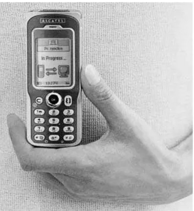
Second generation networks provide voice and limited data services. In addition to these 2G services, 3G systems offer multimedia services adapted to the capabilities of multimedia devices and network conditions with a possibility to provide some content specifically formatted according to the subscriber location. The UMTS Forum in [UFRep9][UFRep13] classifies 3G services into the following six groups as illustrated in Figure 1.6:
Mobile Internet access: a mobile access to the Internet with service quality close to the one offered by fixed Internet Service Providers. This includes full Web access, file transfer, electronic mail, and streaming video and audio.
Mobile Intranet/Extranet access: a secure framework for accessing corporate Local Area Networks (LANs) and Virtual Private Networks (VPNs).
Customized infotainment: a device-independent access to personalized content from mobile portals.
Multimedia messaging service: a means of exchanging messages containing multimedia contents including text, images, and video and audio elements. The multimedia messaging service can be considered as an evolution of SMS where truly multimedia messages can
be exchanged between subscribers. An in-depth description of the multimedia messaging service is provided in Chapters 5 and 6.
Location-based services: location-aware services such as vehicle tracking, local adver-tisements, etc.
Rich voice and simple voice: real-time, two-way voice communications. This includes Voice over IP (VoIP), voice-activated network access, and Internet-initiated voice calls. Mobile videophone and multimedia real-time communications should also be available on high-end multimedia devices.
In the scope of the 3GPP standardization process, the UMTS specification work was divided into two distinct phases. The first phase UMTS, named UMTS Release 99 (also known as Release 3), is a direct evolution from 2G and 2.5G networks (GSM and GPRS networks). The second phase UMTS, also known as UMTS Release 4/5, is a complete revolution introducing new concepts and features.
1.5.2 First Phase UMTS
The UMTS architecture [3GPP-23.101] has to meet the requirements of various UMTS services. These requirements range from real-time voice traffic and bursty data access to mixed multimedia traffic. UMTS is intended to offer a true global service availability. To meet this objective, the UMTS architecture includes terrestrial segments complemented by satellite constellations where necessary.
1.5.3 First Phase UMTS Architecture
The first phase UMTS architecture is based on evolved GSM and GPRS core networks and a specifically tailoredUniversal Terrestrial Radio Access Network(UTRAN). Two duplexing methods, defining how the received signal is separated from the transmitted signal, have been defined as follows:
Universal Terrestrial Radio Access/Time Division Duplex (UTRA/TDD): this method achieves bi-directional transmission by allowing the use of different time slots over the same radio carrier for the transmission of sent and received signals.
Universal Terrestrial Radio Access/Frequency Division Duplex (UTRA/FDD): this method achieves bi-directional transmission by allowing sent and received signals to be transmitted over two separate and symmetrical radio bands for the two links.
The nameWideband CDMA(WCDMA) is also used to identify the two UTRA operating modes (TDD and FDD). Elements composing the first phase UMTS architecture are shown in Figure 1.7.
Elements of the UMTS architecture are grouped into three subsystems: the User Equipment(UE), the access network (UTRAN), and the switching and routing infrastructure, also known as the Core Network (CN). Elements of the UMTS architecture support both circuit-switched connections and packet-switched connections.
1.5.4 User Equipment
The UE, usually provided to the subscriber in the form of a handset, is itself composed of a Mobile Equipment(ME) and aUMTS Subscriber Identity Module(USIM). The ME contains the radio transceiver, the display, and digital signal processors. The USIM is a 3G application on a UMTS IC card(UICC) which holds the subscriber identity, authentication algorithms, and other subscriber-related information. The ME and USIM are interconnected via the Cu electrical interface whereas the UE is connected to the UTRAN via the Uu radio interface. A UE always supports at least one of the operating modes of UTRA: TDD or FDD. In order to allow a smooth transition to UMTS, it is expected that UEs will initially be capable of communicating with legacy systems such as GSM and GPRS. UMTS UEs supporting legacy systems are called multi-mode UEs. The 3GPP classifies multi-mode UEs into the following four categories [3GPP-21.910]:
Type 1:type 1user equipment operates in one single mode at a time (GSM or UTRA). It cannot operate in more than one mode at a time. While operating in a given mode, the user equipment does not scan for or monitor any other mode and switching from one mode to another is done manually by the subscriber.
UE
Uu
The ME contains the radio transceiver, the display, and digital signal processors.
The RNC is the service access point between the UTRAN and the core network.
GMSC Telephone NetworkPublic Switch
Iub
Iub
UTRAN Core Network
UMTS Subscriber Identity Module(USIM), in the form of a smart card, uniquely identifies a subscriber and may store some subscriber specific information.
node Bis in charge of managing the radio communications with UEs attached to one or more cell sites. Also known as the base station.
and performs functions such as user registration, user location the core network with external packet-switched networks.
(HLR) is a database where subscribtion information and user locations are stored.
Type 3:type 3user equipment differs fromtype 2user equipment by the fact that thetype 3 UE can receive more than one mode at a time. However, a type 3 UE cannot emit simultaneously in more than one mode. Switching from one mode to another is performed automatically.
Type 4:type 4user equipment can receive and transmit simultaneously in more than one mode. Switching from one mode to another is performed automatically.
1.5.5 UTRA Network
The UTRAN is composed ofnodes BandRadio Network Controllers(RNCs). Thenode Bis responsible for the transmission of information in one or more cells, to and from UEs. It also participates partly in the system resource management. The node Binterconnects with the RNC via the Iub interface. The RNC controls resources in the system and interfaces the core network.
1.5.6 First Phase UMTS Core Network
The first phase UMTS core network is based on an evolved GSM network subsystem (circuit-switched domain) and a GPRS core network (packet-switched domain). Conse-quently, the UMTS core network is composed of the HLR, the MSC/VLR, and the Gateway MSC (to manage circuit-switched connections), and the SGSN and GGSN (to manage packet-based connections).
1.5.7 Second Phase UMTS
The initial UMTS architecture presented in this chapter is based on evolved GSM and GPRS core networks (providing support for circuit-switched and packet-switched domains, respectively). The objective of this initial architecture is to allow mobile network operators to rapidly roll out UMTS networks on the basis of existing GSM and GPRS networks. From this first phase UMTS architecture, the next phase is to evolve to an architecture with a core network based on an enhanced packet-switched domain only. The objective is to allow a better convergence with the Internet by using IP-based protocols whenever possible. At the end of 1999, 3GPP started the work on the specification of an ‘‘all-IP’’ architecture. In this architecture, the MSC function is split into a control plane part (MSC server) and a user plane part (media gateway). The core network of the second phase UMTS is interfaced with an IP Multimedia Subsystem, abbreviated IMS [3GPP-22.228][3GPP-23.228]. IMS introduces the capability to support IP-based multimedia services such as Voice over IP (VoIP). In IMS, call control is managed with the Session Initiation Protocol (SIP), published by IETF in [RFC-3261], and all network elements are based on IPv6.
1.6 Wireless Application Protocol
The Wireless Application Protocol (WAP) is the result of a collaborative work between many wireless industry players, carried out in the scope of the WAP Forum. The forum, launched in 1997 by Nokia, Phone.Com (now Openwave), Motorola, and Ericsson produced technical specifications enabling the support of applications over various wireless platforms (GSM, GPRS, UMTS, etc.). For this purpose, the WAP Forum identified and defined a set of protocols and content formats according to the standardization process presented in Chapter 2. In 2002, activities of the WAP Forum were transferred to another standardization organization: the Open Mobile Alliance.
1.6.1 Introduction to WAP
The WAP technology is an enabler for building applications (e.g., browsing, messaging, etc.) that run seamlessly over various wireless platforms. The objective of the WAP Forum was to provide a framework for the development of applications with a focus on the following aspects:
Interoperability: applications developed by various parties and hosted on devices, produced by different manufacturers, interoperate in a satisfactory manner.
Scalability: mobile network operators are able to scale services to subscribers’ needs. Efficiency: the framework offers a quality of service suited to the capabilities of
under-lying wireless networks.
Reliability: the framework represents a stable platform for deploying services.
Security: the framework ensures that user data can be safely transmitted over a serving mobile network, which may not always be the home network. This includes the protection of services and devices and the confidentiality of subscriber data.
In line with these considerations, the WAP technology provides an application model close to the World Wide Web model (also known as the web model). In the web model, content is represented using standard description formats. Additionally, applications known as web browsers retrieve the available content using standard transport protocols. The web model includes the following key elements:
Standard naming model: objects available over the web are uniquely identified by Uniform Resource Identifiers (URIs).
Content type: objects available on the web are typed. Consequently, web browsers can correctly determine the type of a specific content.
Standard content format: web browsers support a number of standard content formats such as the HyperText Markup Language (HTML).
Standard protocols: web browsers also support a number of standard protocols for accessing content on the web. This includes the widely used HyperText Transfer Protocol (HTTP).
cope with these constraints, the WAP model leverages the web model by adding the following improvements:
The push technologyallows content to be pushed directly from the server to the mobile device without any prior explicit request from the user.
The adaptation of content to the capabilities of WAP devices relies on a mechanism known as the User Agent Profile(UAProf).
The support ofadvanced telephony featuresby applications, such as the handling of calls (establishment and release of calls, placing a call on hold, or redirecting the call to another user, etc.).
The External Functionality Interface (EFI ) allows ‘‘plug-in’’ modules to be added to browsers and applications hosted in WAP devices in order to increase their overall capabilities.
Thepersistent storageallows users to organize, access, store, and retrieve content from/to remote locations.
TheMultimedia Messaging Service(MMS) is a significant added value of the WAP model over the web model. It relies on generic WAP mechanisms such as the push technology and the UAProf to offer a sophisticated multimedia messaging service to mobile users. MMS is further described in Chapters 5 and 6.
The WAP model uses the standard naming model and content types defined in the web model. In addition, the WAP model includes the following:
Standard content formats: browsers in the WAP environment, known as microbrowsers, support a number of standard content formats/languages including the Wireless Markup Language (WML) and the eXtensible HTML (XHTML). WML and XHTML are both applications of the eXtensible Markup Language (XML). See Box 1.1 for a description of markup languages for WAP-enabled devices.
Standard protocols: microbrowsers communicate according to protocols that have been optimized for mobile networks, including the Wireless Session Protocol (WSP) and HTTP from the web model.
The first WAP technical specifications were made public in 1998 and have since evolved to allow the development of more advanced services. The major milestones for WAP technology were reflected in the availability of what the WAP Forum called ‘‘specifications suites.’’ Each specification suite contains a set of WAP technical specifications providing a specific level of features as shown in Table 1.2.
Box 1.1 Markup languages for WAP-enabled devices
The HyperText Markup Language (HTML) is the content format commonly used in the World Wide Web. HTML enables a visual presentation of information (text, images, hyperlinks, etc.) on large screens of desktop computers. eXtensible Markup Language (XML) is another markup language that is generic enough to represent the basis for the definition of many other dedicated languages. Several markup languages supported by WAP-enabled devices are derived from XML. This is the case of WML and XHTML. WML has been optimized for rendering information on mobile devices with limited rendering capabilities. The eXtensible HyperText Markup Language (XHTML) is an XML reformulation of HTML. Both WML and XHTML are extensible since the formats allow the addition of new markup tags to meet changing needs.
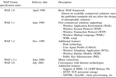
1.6.2 WAP Architecture
Figure 1.9 shows the components of a generic WAP architecture. The WAP device can communicate with remote servers directly or via a number of intermediary proxies and
Table 1.2 WAP Forum specification suites
WAP Forum Delivery date Description
specification suites
WAP 1.0 April 1998 Basic WAP framework
Almost no available commercial solutions since the published standards did not allow the design of interoperable solutions
WAP 1.1 June 1999 First commercial solutions supporting:
- Wireless Application Environment (WAE) - Wireless Session Protocol (WSP) - Wireless Transaction Protocol (WTP) - Wireless Markup Language (WML) - WML script
WAP 1.2 Nov. 1999 Additional features:
- Push technology
- User Agent Profile (UAProf)
- Wireless Telephony Application (WTA) - Wireless Identity Module (WIM) - Public Key Infrastructure (PKI)
WAP 1.2.1 June 2000 Minor corrections
WAP 2.0 July 2001 Convergence with Internet technologies
Additional features:
- Support of MMS 1.0 (3GPP Release 99) - HTTP, TCP, persistent storage
gateways. These proxies/gateways may belong to the mobile network operator or alterna-tively to service providers. The primary function of proxies/gateways is to optimize the transport of content from servers to WAP devices. Supporting servers, as defined by the WAP Forum, include Public Key Infrastructure (PKI) portals, content adaptation servers, and provisioning servers.
1.6.3 Push Technology
In a typical client/server model, a client retrieves the selected information from an application server by explicitly requesting the download of information from the server. This retrieval method is also known as thepull technologysince the client pulls some data from a server. Web browsing is an example of models based on pull technology.
In contrast, another technology has been introduced in the WAP model and is known as the push technology. With push technology, a server is able to push some data to the WAP device with no prior explicit request from the client. In other words, the pull of information is always initiated by the client, whereas the push of information is always initiated by the server.
The push framework, defined by the WAP Forum in [WAP-250], is shown in Figure 1.10. In the push framework, thepush initiatorinitiates the push transaction. The push initiator, usually an application server (e.g., web server, MMS center, etc.) transmits the content to be pushed along with XML-formatted delivery instructions to a Push Proxy Gateway(PPG). The PPG then delivers the push content to the WAP device according to the delivery instructions. The push initiator interacts with the PPG using thePush Access Protocol(PAP). On the other side, the PPG uses thePush Over The Air(OTA) protocol (based on WSP or HTTP) to deliver the push content to the WAP device.
The PPG may implement network-access-control policies indicating whether push initiators are allowed to push content to WAP devices. The PPG can send back a notification to the Push Initiator to indicate the status of a push request (delivered, canceled, expired, etc.).
Three types of browsing content can be pushed to a WAP microbrowser: Service Indication (SI), Service Loading (SL), and Cache Operation (CO). Push SI provides the ability to push content to users to notify them about electronic mail messages awaiting retrieval, news headlines, commercial offers, and so on. In its simplest form, a push SI contains a short message along with an URI. Upon receipt of the push SI, the message is presented to the user who is given the possibility of starting the service (retrieve the content) to which the URI refers. The subscriber may decide to start the service immediately or to postpone it. In contrast to push SI,push SLprovides the ability to push some content to the WAP device without user explicit request. A push SL contains a URI that refers to the push content. Upon receipt of the push SL, the push content is automatically fetched by the WAP device and is presented to the user.Push COprovides a means for invalidating objects stored in the WAP device’s cache memory.
In addition to browsing specific push contents, information can also be pushed to other WAP-based applications such as the WTA agent and the provisioning agent. The MMS client embedded in a WAP device also receives application-specific push messages to notify the user about the availability of new messages and for the delivery of reports.
1.6.4 User Agent Profile
The User Agent Profile (UAProf) specification was first published in the WAP 1.2 specification suite, improved in WAP 2.0, and further enhanced recently by the Open Mobile Alliance. The objective of this specification is to define a method for describing the capabilities of clients and the preferences of subscribers. In practice, this description (known as a user agent profile) is mainly used for adapting available content to the rendering capabilities of WAP devices. For this purpose, the user agent profile is formatted using a Resource Description Framework (RDF) schema in accordance with Composite Capability/
Preference Profiles (CC/PP). The CC/PP specification defines a high-level framework for exchanging and describing capability, and preference information using RDF. Both RDF and CC/PP specifications have been published by W3C. UAProf, as defined by the WAP Forum and updated by OMA in [OMA-UAProf] (version 2.0), allows the exchange of user agent profiles, also known as Capability and Preference Information (CPI), between the WAP device, intermediate network points, and the origin server (web server or MMS center). These intermediate network points and origin servers can use the CPI to tailor the content of WSP/HTTP responses to the capabilities of receiving WAP devices. The UAProf specifica-tion defines a set ofcomponentsthat WAP-enabled devices can convey within the CPI. Each component is itself composed of a set of attributes orproperties. Alternatively, a component can contain a URI pointing to a document describing the capabilities of the client. Such a document is stored on a server known as aprofile repository (usually managed by device manufacturers or by software companies developing WAP microbrowsers). UAProf is composed of the following components:
Hardware platform: this component gathers a set of properties indicating the hardware capabilities of a device (screen size, etc.).
Software platform: this component groups a set of properties indicating the software capabilities of a device (operating system, supported image formats, etc.).
Browser user agent: this component gathers properties characterizing the Internet browser capabilities.
Network characteristics: this component informs on network and environment character-istics such as the bearer capacity.
WAP characteristics: this component advertises WAP browsing capabilities of the device. This includes information on the configuration of the WML browser and so on.
Push characteristics: this component indicates push capabilities of the device. This includes the set of supported content types, the maximum message size that can be handled, and whether or not the device can buffer push messages.
MMS characteristics: this component describes the device capabilities for retrieving and rendering multimedia messages (MMS version, maximum message size, supported content types, etc.).
For a configuration involving a WAP device and a gateway communicating with WSP, RDF descriptions can be encoded in binary with the WAP Binary XML (WBXML). In this context, the CPI is provided by the WAP device as part of the WSP session establishment request. The WAP device can also update its CPI at any time during an active WSP session. Note that the WAP gateway may also override a CPI provided by a device.
The use of UAProf in the context of MMS is further explained in Section 5.21.
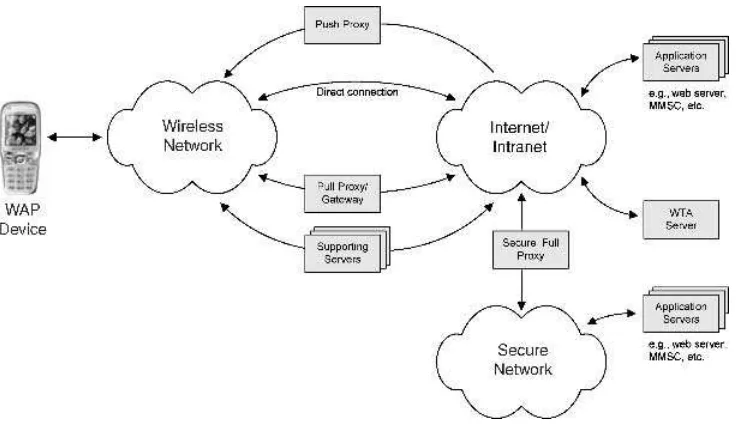
1.6.5 WAP 1.x Legacy Configuration
Figure 1.11 shows the protocol stack of the configuration defined in the WAP specification suite 1.x. This configuration is also supported by the WAP specification suite 2.0 in addition to other configurations. In this configuration, the WAP device communicates with a remote server via an intermediaryWAP gateway. The primary function of the WAP gateway is to optimize the transport of content between the remote server and the WAP device. For this purpose, the content delivered by the remote server is converted into a compact binary form by the WAP gateway prior to the transfer over the wireless link. The WAP gateway converts commands conveyed between datagram-based protocols (WSP, WTP, WTLS, and WDP) and protocols commonly used on the Internet (HTTP, SSL, and TCP).
The Wireless Application Environment(WAE) is a general-purpose application environ-ment in which operators and service providers can build applications (e.g., MMS client or MMS center) for a wide variety of wireless platforms.
TheWireless Session Protocol(WSP) provides features also available in HTTP (requests and corresponding responses). Additionally, WSP supports long-lived sessions and the possibility to suspend and resume previously established sessions. WSP requests and corresponding responses are encoded in a binary form for transport efficiency.
TheWireless Transaction Protocol (WTP) is a lightweight transaction-oriented protocol. WTP improves the reliability over underlying datagram services by ensuring the acknowl-edgment and retransmission of datagrams. WTP has no explicit connection set-up or connection release. Being a message-oriented protocol, WTP is appropriate for implement-ing mobile services such as browsimplement-ing. Optionally, Segmentation And Reassembly (SAR) of packets composing a WTP protocol unit can be supported as described in Section 1.6.8.
The optionalWireless Transport Layer Security(WTLS) provides privacy, data integrity, and authentication between applications communicating with the WAP technology. This includes the support of a secure transport service. WTLS provides operations for the establishment and the release of secure connections.


![Figure 1.6be exchanged between subscribers. An in-depth description of the multimedia messaging3G service categories – source UMTS Forum [UF-Rep-9]](https://thumb-ap.123doks.com/thumbv2/123dok/2435413.1645719/35.476.46.419.65.296/figure-exchanged-subscribers-description-multimedia-messaging-service-categories.webp)