A PRELIMINARY WORK ON LAYOUT SLAM FOR RECONSTRUCTION OF INDOOR
CORRIDOR ENVIRONMENTS
Ali Baligh Jahromia, Gunho Sohna, Mozhdeh Shahbazib, Jungwon Kanga
a
GeoICT Laboratory, Department of Earth, Space Science and Engineering, York University, 4700 Keele Street, Toronto, Ontario, Canada M3J 1P3 - (baligh, gsohn, jkang99)@yorku.ca
b
Department of Geomatics Engineering, University of Calgary,
2500 University Dr NW, Calgary, Alberta, Canada T2N 1N4 - [email protected]
Commission IV, WG IV/5
KEY WORDS: Indoor Layout Reconstruction, Visual SLAM, Point Feature, Gaussian Sphere, Matching
ABSTRACT:
We propose a real time indoor corridor layout estimation method based on visual Simultaneous Localization and Mapping (SLAM). The proposed method adopts the Manhattan World Assumption at indoor spaces and uses the detected single image straight line segments and their corresponding orthogonal vanishing points to improve the feature matching scheme in the adopted visual SLAM system. Using the proposed real time indoor corridor layout estimation method, the system is able to build an online sparse map of structural corner point features. The challenges presented by abrupt camera rotation in the 3D space are successfully handled through matching vanishing directions of consecutive video frames on the Gaussian sphere. Using the single image based indoor layout features for initializing the system, permitted the proposed method to perform real time layout estimation and camera localization in indoor corridor areas. For layout structural corner points matching, we adopted features which are invariant under scale, translation, and rotation. We proposed a new feature matching cost function which considers both local and global context information. The cost function consists of a unary term, which measures pixel to pixel orientation differences of the matched corners, and a binary term, which measures the amount of angle differences between directly connected layout corner features. We have performed the experiments on real scenes at York University campus buildings and the available RAWSEEDS dataset. The incoming results depict that the proposed method robustly performs along with producing very limited position and orientation errors.
1. INTRODUCTION
Over the course of time, humans have changed their lifestyles and increasingly become indoor creatures. Hence, studying the relation of indoor spaces to humans’ activities with respect to safety, security and health is an ongoing and important research field (Rassia, 2017). This relation can be expressed through spatial information. For example, public security can be related to indoor modelling and navigation technology at the time of an incident. Currently, 2D floor plans are the only available indoor spatial data for many large public buildings. These “as -designed” plans may vary from the “as-is” conditions of the buildings. Hence, up-to-date 3D indoor models of these buildings can resolve this information scarcity and contribute to the concept of smart cities in reality.
Scene understanding from a single image (understanding the layout, estimating depth, and detecting obstacles) is quite challenging. Even though this problem is ill-posed, many different methods have been proposed for estimating the indoor layout from a single image (Baligh Jahromi and Sohn, 2015; Liu et al., 2015; Schwing et al., 2013; Yang et al., 2016; Zhang et al., 2014). Two of the leading representative methods were proposed by Lee et al., (2009) and Hedau et al., (2009). They have expressed that the scene structure should be bounded to a specific assumption, in order to estimate the indoor spatial layout. Lee et al., (2009) introduced parameterized models of
indoor scenes by applying rules which guarantee physical validity. Hedau et al., (2009) combined local surface estimates and global scene geometry to parameterize box-shaped scene layouts. This problem can also be resolved by employing prior knowledge of the scene semantics (Liu et al., 2015). Most of the aforementioned methods parameterize the scene layout with a single box, assuming the scene layout to be aligned with the three orthogonal directions defined by vanishing points. Our previous work (Baligh Jahromi and Sohn, 2016) takes the scene layout estimation one step further by estimating a layout for connected indoor corridors. We defined the subject as a hypothesis-selection problem which makes use of middle-level perceptual organization to exploit rich semantic information contained at indoor corridor scenes. Since our method takes advantage of both Orientation Maps and Geometric Contexts for layout hypothesis selection, it is well-suited to describe most indoor corridor scenes.
In this paper, we combined our single image indoor corridor layout estimation method with visual simultaneous localization and mapping (SLAM) to “recognize” or “re-map” the observed indoor corridors. SLAM is a solution for many problems, including autonomous navigation, 3D mapping and inspection. SLAM can be conducted by different sensors, such as laser scanners, cameras, and RGB-D depth cameras; single cameras could also be one of the choices of sensors for SLAM, as they provide valuable visual and contextual information about the ISPRS Annals of the Photogrammetry, Remote Sensing and Spatial Information Sciences, Volume IV-2/W4, 2017
scene. Visual SLAM is aimed at mapping the observed environment progressively, localizing the camera with respect to the map, and detecting loop-closures to avoid error accumulation. Different types of features have been introduced to visual SLAM systems, with point and edge featurings being the most common (Civera et al., 2010; Davison et al., 2007; Eade and Drummond, 2009; Klein and Murray, 2008; Konolige and Agrawal, 2008; Nist´er et al., 2004; Sibley et al., 2010; Zhou et al., 2015).
Point features can be extracted in different ways, such as SIFT key points (Lowe, 2004), Harris Corner detection (Harris and Stephens, 1988), or AGAST corner detection (Mair et al., 2010; Rosten and Drummond, 2006). Point features have favourable properties; they can be easily detected in the image and they can be simply matched, which are both properties suitable for many environments. Hence, systems based on point features are fast and reliable. However, sufficient, reliable point features are not available in the case of objects with no texture or homogeneous texture, e.g. unicolor walls; in fact, in many man-made structures point features are difficult to extract while edges are readily available. In such cases where textures are homogeneous, edge features can replace point features and thus be valuable features. As well, straight line segments can pose additional constraints on the object-space coordinates and provide higher redundancy for camera pose estimation. In spite of these advantages, edge-based SLAM has some serious challenges. A tangible example would be identifying edge correspondences between two consecutive images (Meltzer and Soatto, 2008). Moreover, an edge might be detected in one image as a unique line segment, while it might be sliced into various shorter line segments in another image. Therefore, only a subset of all detected edge features can be used for successful matching.
Most current SLAM algorithms are not able to directly create 3D models of low-texture environments including indoor corridors, since there are only a few distinct features. Hence, the incoming sparse map conveys little information about the geometric characteristics (geometric model) of the indoor corridor scene. In this paper we focus on using a single image estimated indoor corridor layout to initialize the SLAM, and estimate the camera pose and the layout of the corridor scenes. This study demonstrates that scene understanding through straight line-segment detection and orthogonal vanishing point estimation could improve both camera state estimation and direct 3D modelling, especially in low-textured environments. The estimated indoor layout from a single image which initializes the point based SLAM tends to improve the robustness of both state and layout estimations.
The proposed method in this paper takes advantage of both point and edge features to compensate for the insufficiencies of current SLAM systems at indoor corridors. First, we create the spatial layout of the scene by fully applying edge features in a single video frame. Then, we identify the layout structural corner point features which are supported by edge features that are aligned to the true orthogonal directions. We use the layout structural corner point features which are fully supported by the single image edge features to initiate SLAM and enforce it to be bounded to the identified orthogonal directions on the run. Vanishing directions of consecutive video frames are matched on the Gaussian sphere helping the algorithm to limit the feature matching search space. For layout structural corner points matching, we proposed a new feature matching cost function which considers both local and global context information. The
proposed method is able to directly create 3D models while dealing with the presence of few geometrical features and absence of texture by benefiting from image based structural straight line segments. In the following sections, more information about the proposed method will be presented.
2. CAMERA MODEL AND DATA
The pinhole camera model is the simplest model to describe the imaging process by a camera recognized by a flat image plane and a light-barrier hole (the camera perspective centre). In order to reconstruct the rays of light that have created any image point (reversible optical path), the interior orientation parameters (IOPs) of the camera, including the principal distance and the offsets of the principal point, should be known. Also, other intrinsic camera parameters such as lens distortions should be determined, and the image observations should be undistorted to ensure the collinearity condition. In this paper, these camera parameters are calibrated using MATLAB calibration toolbox (Bouguet, 2004).
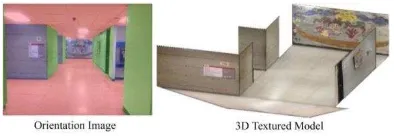
Here, we used the Apple iPhone 4s for collecting the images and videos to create our own dataset. The created dataset is taken from different indoor locations at the York University campus area in Toronto, Canada. Various buildings were crawled for this task; among them are the Petrie Science, Behavioural Science, Ross, and Osgoode Hall buildings. These buildings were chosen due to their free accessibility over time and of course their Manhattan structure aligned indoor corridors. The created dataset is associated with various types of ground-truth such as the corridor layout and corridor type. Also we used the public RAWSEEDS data set for camera trajectory testing (Bonarini et al., 2006). Note that the majority of the selected corridors have simple and rectangular outlines. However, defining the indoor corridor layout in a video frame is sometimes a very challenging task even for human eyes. In most cases, we were able to resolve the issue by considering semantics, such as scene type, presence of windows, doors or other objects. Figure 1 shows a sample image with its ground-truth orientation map and its 3D textured model.
Figure 1. From left to right: ground truth orientation image and the respective 3D textured model.
3. SINGLE IMAGE LAYOUT ESTIMATION
In our previous work (Baligh Jahromi and Sohn, 2016), we proposed a method for single image based indoor modelling which follows a top-down approach. The advantage of this method is that it does not restrict the indoor space layout to only one box. Therefore, the layout can be comprised of multiple connected boxes. This method is also able to handle the ISPRS Annals of the Photogrammetry, Remote Sensing and Spatial Information Sciences, Volume IV-2/W4, 2017
occluded areas in the scene. In this study, we used this modified version of our previously presented method for estimating the indoor corridor layout along with the structural corner points of a corridor scene. Later, the identified structural corner points in the scene will be introduced as point features to the visual SLAM system for initialization.
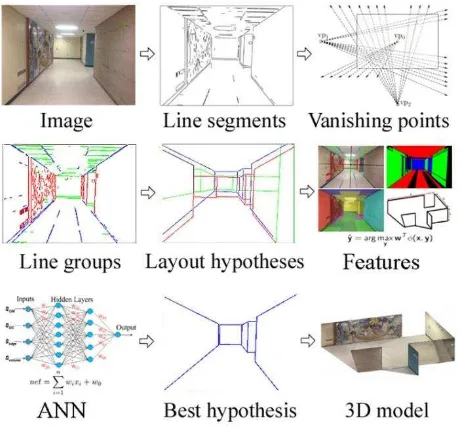
Since point based visual SLAM cannot directly identify the structural features of a scene layout, the utilization of a single image estimated layout for identifying the true orthogonal directions and structural corner points is justified. This idea enables the SLAM to benefit from the scene layout and its orthogonal directions on the run. The scene layout orthogonal directions will remain intact during a walk through a corridor scene. In a low texture environment, these orthogonal directions, which are identified from the layout estimated from a single image, can connect consecutive video frames to each other. Having identified the orthogonal directions and the structural corner points of the scene for every video frame, the indoor corridor scene layout can be estimated in real-time by applying the SLAM mechanism. Keep in mind that the point based visual SLAM system itself can map the environment, but the incoming map needs post processing to identify the true geometric scene layout. In other words, it is unable to directly identify the scene layout, which is instead accomplished through the single image layout estimation procedure. In the following paragraph, a summary of our modified indoor layout estimation method is provided. Figure 2 shows the workflow of this modified method.
Figure 2. The method detects edges and groups them into line segments. It estimates vanishing points, and creates layout hypotheses. It uses the scoring function (parameters optimized by ANN) to evaluate hypotheses, and finally converts the best
hypothesis into a 3D model.
The overall workflow of the modified version of our previously presented method is as following: 1) Edges are extracted from a single image, and grouped into straight line segments. 2) Line segments are grouped based on parallelism, orthogonality, and convergence to the common vanishing points. 3) Physically valid major box layout hypotheses are created using detected
line segments and virtual rays created from vanishing points. 4) The created major box layout hypotheses are scored using a scoring function, the parameters of which are optimized through artificial neural network (ANN) learning. 5) Only, 15% of the layout hypotheses that get higher scores remain in the hypothesis generation pool and the rest are discarded. 6) The remaining major box layout hypotheses are deformed by sequentially introducing side box hypotheses to their structure. Note that the maximum number of side box hypotheses that can be integrated to a major box hypothesis is four. 7) The generated side box hypotheses are also scored using the same scoring function. 8) Finally, the best layout hypothesis is selected by comparing the scores, and is converted to a 3D model. More details on this regard can be found in Baligh Jahromi and Sohn (2016).
4. PROPOSED LAYOUT SLAM
Here, we followed the mathematical concepts developed by Davison (2003) and modified the open-source MATLAB code provided by Civera et al., (2010). We have modified the initialization scheme, and both feature selection and feature matching blocks in their proposed visual SLAM algorithm. The key concept of the proposed method is probabilistic scene layout estimation. Our method represents the current estimate of the state of the camera and all features as well as the uncertainty of these estimates. The scene layout is initialized through its layout structural corner points at system start-up and grows dynamically as it is updated by the Extended Kalman Filtering (EKF). Camera and features state estimates are updated during camera motion and layout feature observation. As soon as a new layout structural corner point feature is observed, the system will grow with new states. The mean estimates of the camera and features states as well as a first-order uncertainty distribution associate the estimated scene layout over time. The created scene layout can be represented by a state vector ̂ and covariance matrix P. State vector ̂ is composed of the camera and features state estimates:
̂ =
( ̂ ̂ ̂ . . )
, =
[
. . . .
. . ..
. . . . . . . .]
(1)
Here, the camera state vector (xv) comprises of a three dimensional position vector (rw), orientation quaternion (qwc), velocity vector (vw), and angular velocity vector (�w). The superscripts W and C represent the world frame and the camera frame respectively. Feature states (yi) represent the three dimensional position vectors of identified points. The feature vector contains two types of features including normal point features and layout structural corner point features. Although both of these features are points, they will go through different schemes for selection and matching in the proposed system. Normal point features follow the rules set by Davison (2003), while layout structural corner point features will benefit from local image orientations and global cues of indoor structures for selection and matching, which will be discussed later. Note that the probability distribution over the above parameters is approximated as Gaussian distribution.
= ( � �
) (2)
Here, the scene layout permits accurate real-time localization. Hence, the primary goal is to capture a sparse set of high-quality layout structural corner points and maintain them in the system for as long as possible. The critical role of maintaining features as long term land marks in visual SLAM systems has been irrefutably proven in SLAM research. These features can influence the correlation between the map and the camera poses estimates. These features may have position estimates which are uncertain in the reference frame but they highly correlate the camera pose estimates in many sequences. Holding correlation information of these features in the system for a long time can improve estimates of the other related features, and enables the system to recognize known areas after short periods of neglect.
Here, the goal is to maintain the layout structural corner point features as long term land marks in the system to improve the camera pose estimates. However, the ability to measure the layout structural corner point features in many sequences is directly affected by the adopted motion model in the system. Introducing a motion model for a camera which is carried by a person walking inside a corridor is not fundamentally different from the motion model of a wheeled robot moving smoothly on a flat surface. Davison (2003) adopted a “constant velocity, constant angular velocity model” which assumes large accelerations to be unlikely and imposes smoothness to the camera motion. The assumption is that at each time step an amount of unknown acceleration aw and angular acceleration αw with Gaussian distribution and zero mean generates an impulse of the velocity and angular velocity in the system:
= � = � ∆� ∆ (3)
The uncertainty growth rate in the Davison (2003) motion model is determined by the covariance size of the noise vector n. Even though large covariance enables the system to cope with rapid accelerations, increasing the uncertainty in the system will affect the estimates and necessitates perfect measurements to be made at each time step to constrain estimates. Accomplishing perfect measurements in a low textured corridor environment with a relatively narrow angle camera is unlikely to a great extent. Therefore, small covariance which indicates a very smooth motion with small accelerations has to be considered. Thus, a new method must be implemented for enabling the system to cope with sudden rapid camera movements.
In order to successfully apply the visual SLAM, not only must camera and features state be well predicted, but proper feature observations have to be made as well. Davison (2003) used the pinhole camera model to predict the image position (u, v) of a 3D point feature:
ℎ�= � − , ℎ = = ( − � ℎ�� ℎ��
− � ℎ�� ℎ��
) (4)
Here, u0, v0, fku, and fkv are the camera intrinsic calibration parameters, � is the rotation matrix, and ℎ� is the vector connecting the camera projection center to the 3D point feature
in the camera frame C. The uncertainty of the above prediction can be represented by the innovation covariance matrix Si. Considering Si, an elliptical search window in the image space can be introduced for the predicted point where its corresponding match should lie with high probability. On one hand, � can affect the position of the predicted point’ on the other hand � itself is affected by the applied motion model in the prediction step of the EKF. Since, a very smooth motion with small accelerations is more suitable for the system; we introduced a rotation compensation variable “δ” to the system to cope with sudden rapid camera movements.
�− = �− ′ + �, − (5)
Here, �− ′ is the amount of rotation in the system after update phase has been accomplished in the EKF at step t-1. This variable will be replaced by �− in the system before making predictions for step t. Also, �, − is the amount of rotation difference between two consecutive steps (t-1 and t), which is calculated independently using estimated vanishing points. Here, we assume that �, − is free of error and its uncertainty is not needed to be considered in the EKF. Therefore, the camera state prediction would be the same as the one proposed by Davison (2003):
= (
� �� �
� �
) = (
+ + � ∆
� × � + � ∆
+ � � + �
) (6)
In the above equation, the notation � + � ∆ denotes the quaternion defined by the angle-axis rotation vector � +
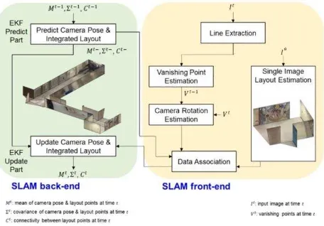
� ∆ . Figure 3 shows the overall workflow of the proposed method.
Figure 3. The workflow of the proposed method.
As mentioned before, this study proposes a solution for degrading the effect of abrupt camera rotations. The proposed method identifies the vanishing directions for consecutive video frames on the Gaussian sphere and matches the corresponding vanishing directions to estimate the amount of relative camera rotation between two frames. By applying the same amount of rotation to the estimated layout in the former video frame, the ISPRS Annals of the Photogrammetry, Remote Sensing and Spatial Information Sciences, Volume IV-2/W4, 2017
layout position in the later video frame can be roughly estimated. This helps the algorithm to facilitate the matching while it is trying to find the identified features in the next video frame. In the following sections more information on the above subject will be presented.
4.1 Vanishing Points on Gaussian Sphere
Straight parallel lines in 3D space can be projected onto the 2D image plane, and they will intersect at a point called a vanishing point. Vanishing points have special geometric attributes which can be employed in many computer vision applications, such as rotation estimation and camera calibration. Since a vanishing point is a translation-invariant feature, rotation can be more accurately estimated by using vanishing points. Usually, at indoor places, the Manhattan world constraint is applicable. Hence, a triplet of mutually orthogonal vanishing points commonly appears in the scene, which facilitates the 3D reconstruction. This constraint allows vanishing points to be matched more easily in a small-baseline image sequence and improves the robustness of the rotation estimation while noisy line segments may be extracted from the image sequence. Therefore, by applying this constraint, the vanishing point correspondences can be quickly found and the real-time rotation estimation in an image sequence can be achieved.
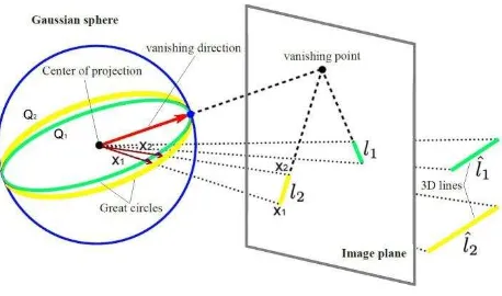
In the pinhole camera model, the Gaussian sphere is a unit sphere which is placed on the center of projection. In figure 4, a straight line on 3D space is projected onto the image plane and its corresponding line on the image plane is represented by a great circle. This circle is created by the intersection of the unit sphere and a plane which contains both the line and the center of projection. As can be seen in this figure, the respective great circles of parallel lines are intersecting at a specific point on the unit sphere. The direction from the center of projection to this specific intersection point is the vanishing direction.
Figure 4. Imaged line segments l1, l2 of 3D parallel lines intersect at a vanishing point on the image plane. The same
vanishing point can be parametrized as a vector pointing towards the intersection of great circles of lines l1, l2 and Gaussian sphere (original figure from Kroeger et al., 2015).
This concept can also be parametrized by modeling vanishing point locations on the Gaussian sphere. A point ṽ in homogeneous image coordinates can be normalized by v = K-1 ṽ, while K is the camera calibration matrix. The plane Q is spanned by the center of projection at [0 0 0]T. The vanishing direction (D) of line segments l1, l2 can be estimated from the intersection of their interpretation planes Q1, Q2 on the Gaussian
sphere (Kroeger et al., 2015). Vanishing direction on 3D space
d ∈ R3 can be defined through homogeneous coordinates D ∈ P3. In this case, the following equation is applicable:
D = [ dT 0 ]T = [ X Y Z 0 ]T (7)
Having identified the vector D in homogeneous coordinates, it can be transformed into vector D’ by a 4 × 4 rotation and translation matrix in 3D space as:
D’ = [
× ] D = [ ] (8)
Here R is the rotation matrix and T is the translation vector. As can be seen in the above equation, the transformed vanishing direction equals Rd. This indicates that the vanishing direction transformation is influenced by rotation only. Since a vanishing point on image plane is the projection of the vanishing direction, it can have the same property (Kroeger et al., 2015). Therefore, the relative rotation of the camera between two consecutive video frames can be estimated by identifying vanishing points in each of these frames. In this study, after estimating the orthogonal vanishing points in each video frame, the corresponding vanishing directions were identified on the Gaussian sphere. Since vanishing directions of two consecutive video frames are referring to the same indoor corridor layout, transforming from one to another will identify the amount of relative rotation between these two frames. Hence, having identified the relative rotation between consecutive vanishing directions, the same amount of rotation can be applied to the structural elements of the indoor layout (lines and corners) on the Gaussian sphere. Therefore, the estimated layout in frame t-1 can be back projected onto frame t with no rotation difference. This process enables the algorithm to remove the effect of abrupt camera rotation changes and facilitates the matching of structural layout features in the image space.
4.2 Feature Extraction and Matching
As discussed in the previous sections, in the proposed method, the estimated indoor layout of video frame “t-1” will be
projected onto the video frame “t” by the help of matching vanishing directions of both video frames on the Gaussian sphere. Since the transition vector of the camera’s center of projection between two video frames is assumed to be zero, which is not true in reality, the projected layout of the video frame “t-1” will not reside on the exact layout of video frame
“t”. Therefore, a matching scheme has to be introduced to find
the corresponding structural corner features in video frame “t”.
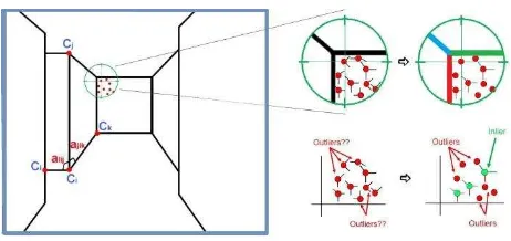
Considering the straight line segment and vanishing point estimation errors, the size of the matching search space may vary in different algorithms. In this study the 11×11 pixel search space size was chosen to perform the matching scheme. After the projection of the estimated indoor layout of the previous video frame to the current video frame, the matching scheme is started. Candidate structural corner point features are generated through intersection of the detected straight line segments in the current video frame. It should be noted that the estimated indoor layout provides valuable information about the type of the structural corner points which needed to be found in the current video frame. Hence, the number of potential corner point matching candidates can be reduced to some extent by considering the type of the projected layout corner points in the current video frame. Figure 5, shows how a candidate corner point can be eliminated from the list of potential structural ISPRS Annals of the Photogrammetry, Remote Sensing and Spatial Information Sciences, Volume IV-2/W4, 2017
corner point candidates by considering the orientation of its supporting line segments.
Figure 5. Left: angles between connected corners and structural corner point candidates are identified around the projected layout corner. Right: candidate corner points are classified by
considering the orientation of their supporting line segments.
Once the true candidate corner points are identified in the current video frame, the matching scheme is started. While a corner point feature provides only local structure information about the indoor layout corner, other features must be included in the matching scheme to impart the global structure information for configuration of the indoor layout. Here, these features are set by selecting all of the other structural corner points which are directly connected to the corner feature in question. In this paper two types of features were adopted, including the planar orientations which are defined by the type of corner feature in question and angles (αi, αj, αk…) between the lines connecting the corner in question (Ci) to the other directly connected corners (Cj, Ck, Cl…). Figure 5, shows the angle features for corner feature Ci. Here, the proposed cost function consists of a unary term, which measures the orientation differences of the matched corners, and a binary term, which measures the angle differences between corresponding layout features, as following:
= [� × ∑�=1 + − � × ∑�=1 ] (9)
Here, “a” is the weight value which balances the unary term and
the binary term (a = 0.5). Also, “n” is the number of image
pixels in the search space of the matched corner features and “m” is the number of other directly connected corner features.
The unary term O(i) measures pixel to pixel orientation difference between the matched corner features derived from the estimated indoor layout of previous video frame and the current video frame:
� = | − �| (10)
The binary term is designed to deal with relationships between neighbor features in terms of angles. It is calculated for all corner features which are directly connected to the matched corner features derived from the indoor layout and the current video frame. For angle differences, we start from the vertical vanishing point direction at each corner feature and count the corresponding angles clockwise. The angle difference |� −
�� | between the lines connecting the matched corners
� , �� and the other directly connected corners
� , � , ��, �� is valued by either 0 or 1. Since the suggested
layout corner match must maintain the orthogonality of the indoor structure, if the connected line between the suggested corner match and the other corners converge to the estimated vanishing point considering the tolerance of the vanishing point estimation error, then the value of the angle difference would be 0 and 1 otherwise:
� = |� − �� | = { � � = ��
ℎ � (11)
For each indoor model, a corner feature and its corresponding layout corners which minimize the cost function are selected as optimal matches. Note that if the minimum cost is larger than a certain threshold (= 0.7), the matches are not considered as matched corners. This threshold has considerable impact on the performance of the proposed matching cost function. Hence, an experiment is performed for optimizing this threshold, which will be presented in the experiments section.
5. EXPERIMENTS
As stated before, we used a cell phone (Apple iPhone 4s) camera to video record indoor corridors and create a small dataset. For testing the validity of the proposed method, three different video sequences from the prepared dataset have been used along with the data set of Biccoca_2009-02-25b from the RAWSEEDS. In our data set, all sequences were recorded by an iPhone 4s video recording camera with video stabilization quality and the ability to capture up to 30 frames per second. In order to achieve the highest accuracy, the proposed method is only examined by video sequences of the highest resolution (1920×1080 pixels) in this experiment.
The system starts its first motions from a position observing the indoor corridor from the mid part of the hallway while a number of indoor corridor structural corner points (top and bottom corners of the other corridors on the side) and other salient feature points (for instance points on the paintings) are visible. Since, the three dimensional layout of the scene was created prior to the SLAM initialization (the model created from the first captured video frame), the corresponding structural layout corner points were used as the initial features for the modified SLAM method initialization.
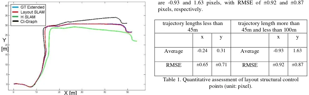
We test the proposed method on the RAWSEEDS data set which is a benchmark for SLAM related problems. The data sets are collected by a wheel robot in an office building. The indoor scenes consist of various types of architectural features. Yet, our interest is limited to corridor scenes. Therefore, we only considered the first three connected corridors on the data set of Biccoca_2009-02-25b, for camera trajectory testing. We used data of the frontal camera and evaluate the method by aligning the resultant trajectory with the extend ground truth and other related SLAM algorithm results provided by Bonarini et al., (2006). The results are shown in figure 6. The proposed method produces maximum position errors about 0.27 m along the first three corridors path with no loop-closing.
Figure 6. Results of different SLAM algorithms (trajectories) aligned with the ground truth (blue trajectory) for the first three
corridor scenes of Biccoca_2009-02-25b, data set.
In addition to camera trajectory comparisons, we performed the validation of the estimated layouts in the image space where the ground truth layouts were provided for a sparse set of video frames. Figure 7 shows the estimated indoor layout in 3D space for a selected video from the Petrie Science building first floor corridor. In this video, the camera moves towards the end of the corridor. As mentioned before, in this preliminary work we focused on the quality of the generated indoor model in the image space for the evaluation of the proposed method. For each of the selected video sequences, a sparse number of video frames (almost 1 frame per 3 seconds) were selected and the corresponding indoor layouts were reconstructed by manually identifying structural features on the selected video frames (ground truth generation). The experiments were conducted on the video frames captured from three corridor scenes (all from the Ross building) to perform the accuracy assessment. The approximate trajectory lengths of the selected videos were 6.5m, 37m and 89m respectively.
Figure 7. Left: video frame and identified point features. Middle: camera and structural corner points positions in 3D space from top view. Right: estimated layout rotated in 3D.
In order to quantitatively evaluate the proposed method, we considered RMSE of layout structural corner points in the image space for camera trajectory lengths shorter and longer than 45 meters (Table 1). Here, 45 meters threshold is selected intuitively. The result with manually digitized indoor layouts shows that the average difference in x and y directions on layout structural corner points for trajectory lengths less than 45 meters are -0.24 and 0.31 pixels, with RMSE of ±0.65 and ±0.71 pixels respectively. The result for trajectory lengths of more than 45 meters shows that the average differences in x and y directions
are -0.93 and 1.63 pixels, with RMSE of ±0.92 and ±0.87 pixels, respectively.
trajectory lengths less than 45m
trajectory length more than 45m and less than 100m
x y x y
Average -0.24 0.31 Average -0.93 1.63
RMSE ±0.65 ±0.71 RMSE ±0.92 ±0.87
Table 1. Quantitative assessment of layout structural control points (unit: pixel).
As expressed in the previous section, the cost function threshold for corner points matching has an impact on the performance of the algorithm. If the minimum cost is larger than a certain threshold, the matches are not considered matched corners. In order to evaluate the impact of the cost function threshold, the RMSE of the structural control points was measured with different values for the cost function threshold on the 89m trajectory length video (Table 2). As the minimum cost function threshold becomes larger, the number of matched corner points increases. Considering the accuracy of the manually digitized layouts, the cost function threshold itself will be affected by the quality of the prepared ground truth layouts. However, in this study the impact of the accuracy for both the vanishing point estimation algorithm and the prepared ground truth data are not considered in the evaluation of the proposed cost function. The results with the prepared ground truth layouts show that the cost function accuracy deteriorates as the threshold becomes larger. Also, when low values are assigned to the cost function threshold, the number of matched corner point features is too small to recover a physically plausible layout in the image space. Therefore, an optimal value for the cost function threshold can provide better accuracy to the estimated indoor corridor layouts.
Cost function threshold
0.5 0.6 0.7 0.8 0.9
No. of matched corners
55 84 109 121 137
RMSE x ±0.83 ±1.05 ±0.92 ±1.21 ±1.76
y ±1.17 ±1.08 ±0.87 ±1.36 ±1.55
Table 2. The impact of cost function threshold (unit: pixel).
6. CONCLUSION
One of the most important problems in the area of visual navigation is to keep track of camera’s different poses in an unknown environment. In this paper, we presented a solution for real time indoor corridor layout estimation in the context of visual SLAM and single image indoor modeling perception. The indoor corridor layout is estimated for one frame of the captured video which identifies the true orthogonal directions specified by vanishing points. The estimated single layout initializes the visual SLAM and enforces it to be bounded to the identified orthogonal directions on the run. Vanishing point matching on a unit sphere enables the algorithm to deal with abrupt camera movements and limits the feature matching search space. The proposed feature matching cost function considers both local and global context information, which makes it more reliable while dealing with indoor structural corner feature matching challenges. As well, utilizing image ISPRS Annals of the Photogrammetry, Remote Sensing and Spatial Information Sciences, Volume IV-2/W4, 2017
based straight line segments enable the algorithm to deal with the presence of few geometrical features and absence of texture in the scene. The proposed method performs robustly and produces small position and orientation errors.
ACKNOWLEDGEMENTS
This research was supported by the Ontario government through Ontario Trillium Scholarship, NSERC Discovery, and York University. In addition, the authors wish to extend gratitude to Mr. Kivanc Babacan who consulted on this research.
REFERENCES
Baligh Jahromi, A. and Sohn, G., 2015. Edge Based 3D Indoor Corridor Modeling Using a Single Image. ISPRS Annals of the Photogrammetry, Remote Sensing and Spatial Information Sciences, Volume II-3/W5, pp. 417–424.
Baligh Jahromi, A. and Sohn, G., 2016. Geometric Context and Orientation Map Combination for Indoor Corridor Modeling Using a Single Image. International Archives of the Photogrammetry, Remote Sensing & Spatial Information Sciences, 41. Volume XLI-B4, pp. 295–302.
Bonarini, A., Burgard, W., Fontana, G., Matteucci, M., Sorrenti, D. and Tardos, J., 2006. RAWSEEDS: Robotics Advancement through Web-publishing of Sensorial and Elaborated Extensive Data Sets, IROS’06 Workshop on Benchmarks in Robotics Research, Beijing, China. pp. 16–23.
Bouguet, J. Y., 2004. Camera calibration toolbox for matlab.
Civera, J., Grasa, O. G., Davison, A. J., and Montiel, J. M. M., 2010. 1-Point RANSAC for extended Kalman filtering: Application to real-time structure from motion and visual odometry. Journal of Field Robotics, 27(5), pp. 609-631.
Davison, A. J., 2003. Real-Time Simultaneous Localisation and Mapping with a Single Camera. In: International Conference on Computer Vision. Vol. 3, pp. 1403-1410.
Davison, A. J., Reid, I. D., Molton, N. D., & Stasse, O., 2007. MonoSLAM: Real-time single camera SLAM. IEEE transactions on pattern analysis and machine intelligence, 29(6), pp. 1052–1067.
Eade, E. and Drummond, T., 2009. Edge landmarks in monocular slam. Image and Vision Computing, 27(5), pp. 588– 596.
Harris, C. and Stephens, M., 1988. A Combined Corner and Edge Detector. In Proceeding of the Alvey Vision Conference, pp. 147–152.
Hedau, V., Hoiem, D., and Forsyth, D., 2009. Recovering the spatial layout of cluttered rooms. In: Proceedings of the 12th
IEEE International Conference on Computer Vision, pp. 1849– 1856.
Klein, G. and Murray, D., 2008. Improving the Agility of Keyframe-Based SLAM. In: Proceedings of the European Conference on Computer Vision, volume 2, pp. 802–815.
Konolige, K. and Agrawal, M., 2008. FrameSLAM: From Bundle Adjustment to Real-Time Visual Mapping. IEEE Transactions on Robotics, 24(5), pp. 1066–1077.
Kroeger, T., Dai, D., and Van Gool, L., 2015. Joint vanishing point extraction and tracking. In Proceedings of the IEEE Conference on Computer Vision and Pattern Recognition, pp. 2449-2457.
Lee, D.C., Hebert, M., Kanade, T., 2009. Geometric reasoning for single image structure recovery. In: Proceedings of the IEEE Conference on Computer Vision and Pattern Recognition, pp. 2136–2143.
Liu, C., Schwing, A.G., Kundu, K., Urtasun, R. and Fidler, S., 2015. Rent3D: Floor-plan priors for monocular layout estimation. In: Computer Vision and Pattern Recognition (CVPR), pp. 3413-3421.
Lowe, D. G., 2004. Distinctive image features from scale-invariant keypoints. International Journal of Computer Vision, 60(2), pp. 91–110.
Mair, E., Hager, G. D., Burschka, D., Suppa, M. and Hirzinger, G., 2010. Adaptive and Generic Corner Detection Based on the Accelerated Segment Test. In: Proceedings of the European Conference on Computer Vision, pp. 183–196.
Meltzer, J. and Soatto, S., 2008. Edge Descriptors for Robust Wide-Baseline Correspondence. In: Proceedings of the IEEE Conference on Computer Vision and Pattern Recognition, pp. 1–8.
Nist´er, D., Naroditsky, O. and Bergen, J., 2004. Visual odometry. In: Proceedings of the IEEE Conference on Computer Vision and Pattern Recognition, volume 1, pp. 1–8. Rassia, S. T., 2017. Workplace Environmental Design in Architecture for Public Health: Impacts on Occupant Space Use and Physical Activity. Springer.
Rosten, E. and Drummond, T., 2006. Machine learning for high-speed corner detection. In: Proceedings of the European Conference on Computer Vision, pp. 430–443.
Schwing, A. G., Fidler, S., Pollefeys, M., Urtasun, R., 2013. Box in the box: Joint 3d layout and object reasoning from single images. In: Proceedings of the IEEE International Conference on Computer Vision, pp. 353-360.
Sibley, G., Mei, C., Reid, I. and Newman, P., 2010. Vast-scale Outdoor Navigation Using Adaptive Relative Bundle Adjustment. International Journal of Robotics Research, 29(8), pp. 958–980.
Yang, S., Maturana, D., and Scherer, S., 2016. Real-time 3D scene layout from a single image using convolutional neural networks. In Robotics and Automation (ICRA), IEEE International Conference, pp. 2183-2189.
Zhang, Y., Song, S., Tan, P., & Xiao, J., 2014. PanoContext: A whole-room 3D context model for panoramic scene understanding. In: Proceedings of the European Conference on Computer Vision, pp. 668-686.
Zhou, H., Zou, D., Pei, L., Ying, R., Liu, P., and Yu, W., 2015. StructSLAM: Visual SLAM with building structure lines. IEEE Transactions on Vehicular Technology, 64(4), pp. 1364-1375. ISPRS Annals of the Photogrammetry, Remote Sensing and Spatial Information Sciences, Volume IV-2/W4, 2017