A Study of Mobile Robot Control using
EEG Emotiv Epoch Sensor
Timothius Victorio Yasin*,aFelix Pasila, and Resmana Lim
Electrical Engineering Department, Petra Christian University, Jl. Siwalankerto 121-131, Surabaya, 60234, Indonesia
Abstract. The study was using an EEG Emotiv Epoc+ sensor to recognize brain activity for controlling a mobile robot’s movement. The study used Emotiv Control Panel software for EEG command identification. The commands will be interfaced inside Mind Your OSCs software and processing software which processed inside an Arduino Controller. The output of the Arduino is a movement command (ie. forward, backward, turn left, and turn right). The training methods of the system composed of three sets of thinking mode. First, thinking with doing facial expressions. Second, thinking with visual help. Third, thinking mentally without any help. In the first set, there are two configurations thinking with facial expression help as command of the mobile robot. Final results of the system are the second facial expressions configuration as the best facial expressions method with success rate 88.33 %. The second facial expression configuration has overall response time 1.60175 s faster than the first facial expressions configuration. In these two methods have dominant signals on the frontal lobe. The second facial expressions method have overall respond time 6.12 and 9.53 s faster than thinking with visual, and thinking without help respectively.
Key words:EEG, emotiv epoch sensor, mobile robot control.
1 Introduction
The duration from the beginning of human life, the human always has an actuator, which hands, eyes, feet, mouth and some of the other senses. Without realizing it at the root of this actuator controller itself is the brain, where the development of technology directly to the brain is less developed than others. Then, with increasing awareness of the multiple sides of this, then developed a method of the analysis of brain signals.
Electroencephalography or commonly referred to EEG, is a method of recording electrical activity in the brain to detect or analyze an electrical signal flowing to the brain. EEG using a unit where the voltage will enable the electrodes to record signals (pulse) of the brain [1]. EEG has begun to be used to find and analyze an illness, ranging from Alzheimer's disease, epilepsy, brain tumors, and several other diseases associated with the brain wave signals that are drawn from parts of the head [2]. In another way, EEG testing is also conducted to test the brain stem death (death brain stem), which indicates the presence or absence of the brain's response to stimuli both physically, as well as non-physical. The utilization of EEG sensors has been applied to virtual simulation [3], and also robots in the assistive technologies [4‒8], and also applied to face recognition on smartphones [5]. In this project, the Emotiv Epoc+ EEG sensor[9] is used as input to capture facial expressions will give orders to the Arduino[10] as a controller of the mobile robot used.
2 System description
This section will explain about the design of the robot movement control system using Emotiv EEG sensors. Explanation will include the system in general, workflow systems, EEG training process, and design software on the Arduino.
2.1 System setup
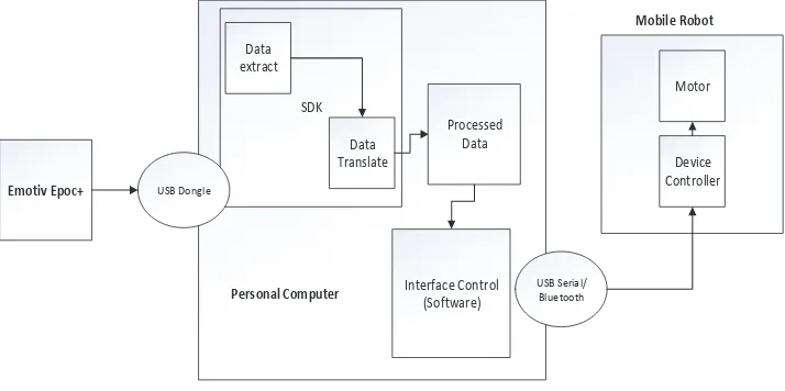
This system has a sensor input EEG Emotiv Epoc+ to record the activity of brain signals related to a computer via a USB dongle, computer or laptop as the brain of the system for processing input from Emotiv Epoc+, USB serial or Bluetooth from a computer that is connected to the output of the Arduino connected with motor driver to drive the two motors on the mobile robot. Explanation diagrammed through the design of Figure 1.
Emotiv Epoc+
The system comes up with connection between input, processor, and output, will be shown as Figure 2 below.
Fig. 2. System hardware diagram.
2.2 EEG training process
Table 1. Movements command for expression and visual method.
On the third method, think without assistance, will be used to think of a direction or movement in a "forward", "backward", "left" or "right".
2.3 Design software on Arduino
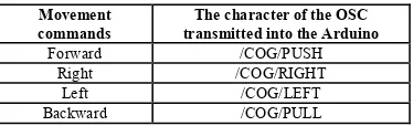
On the design of the software or the software on the Arduino, conducted a reading of the injunction through software processing, a message is received in a message of the OSCcommand which will be known as movement on the robot. The character of the OSC messages described in Table 2 below.
Table 2 . Character table OSCon movement commands.
Movement
The process of programming in Processing outline is as follows: (i). Processing software read commands of the OSC messages.
(ii).The commands of the OSC messages has received value in floating point as a representation of power level. (iii).Power level of a certain command is stored in the variable named "NilaiBaca".
(iv).The value in the "NilaiBaca" is compared against the threshold as triggers to execute commands the movements of a robot.
3 System testing and analysis
3.1 Emotiv Epoc+ methods testing
This test have purpose to find out the best method of time respond using Emotiv Epoc+. In this testing will be done against the three kinds of comparative method. First, the method of facial expression (1st and 2nd configurations), second
visual thinking method, and then method of thinking without assistance. This test has the measurements in time (seconds) to see the response time of each method on the given command. Testing through 20 times on any orders from a variety of different methods, the results obtained as in Table 3 below.
Table 3 . The results of the response time average in the four methods.
Command Average response time (s)
Expression 1 Expression 2 Visual Mind
Forward 3.52 3.50 7.90 14.47
Based on the results of testing on Table 3, it can be seen that the method of facial expression 2 has the response time is much faster than other methods, with an overall average time through 20 times testing on advanced are 3.5 s for forward, 2.79 s for backward, 4.16 s for left and 4.23 s for right.
3.2 Result graphs and mapped figures
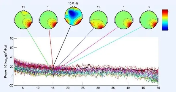
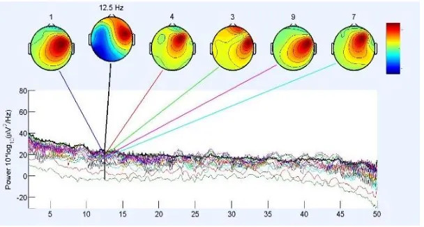
The results of testing on every command by a better method, the method of facial expression two generates the image of the brain's signals on the head. An overview of brain signals on this head has a goal to see the signals of the dominant head area when the user performs the method expression on every command. The dominant signals is shown by using EEGLAB software data, which is described as in Figure 3, Figure 4, Figure 5, and Figure 6.
Based on the results of the recording data entered into EEGLAB, the result of dominant channels are1, 5, 6, 11, 12 (AF3, T7, P7, FC6, F4 respectively), with an analysis on the working frequency Beta (12.5 Hz to 30 Hz). Forward command is initialized with a smile and thrilling molars down as well as up, causing the presence of a dominant signal generated on the Parietal or parts of the brain that respond to stimuli, one of them is the pressure. This command result is shown in Figure 3 below.
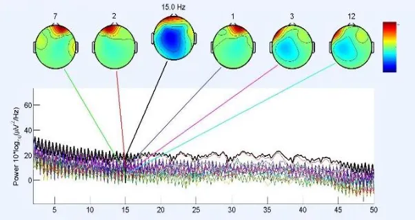
The next command is backward, which has the result of dominant channels are1, 2, 3, 7, 12 (AF3, F3, F7, O1, and F4 respectively). Backward command is initialized with raised eyebrows, so dominant signals generated in result is shown in Figure 4 below.
Fig. 4. The results of the mapping of the backward command.
In the third command, which is the left command movement, has a result of dominant channels are1, 3, 4, 7, 12 (AF3, F3, FC5, O1, and AF4 respectively). The left command is initialized with left eye blink, so that the signal generated by the dominant part of the frontal lobe, particularly on the left side of the head. This command result is shown in Figure 5 below.
Fig. 5. The results of the mapping of the left command.
Fig. 6. The results of the mapping of the right command.
3.3 Robot control movement testing
This test is the final process of the system, this test have purpose to find out the mobile robot's movement based on data that has been initialized by the user, and know the standard value (threshold value) against users who have done the training.
3.3.1 The determination of threshold values
At the beginning of this testing, after doing the reading against one user for 8 s (refer to data that is recorded using the TestBench, and length of the training data in Emotiv Control Panel), obtained the following results for the fourth reading of the initialized command to move the mobile robot, which is described in the Figure 7, Figure 8, Figure 9 and Figure 10.
Fig. 8. Backward threshold value determination graph.
Fig. 9. Left threshold value determination graph.
Based on the results of recording data for 8 s (determined training data for initialization), the data will be averaged to find the threshold value on each command movement. The results of each command are 0.47 396 for forward command, 0.57 822 for backward command, 0.49 235 for left command, 0.43 484 for right command. The value scales are 0 to 1, which represent the power of representing the same command which has been trained before. The closer of the value to 1, it means that the command has the similar pattern or power to the master data. Finally, these values will be used as a trigger to execute a command on a mobile robot’s movement.
3.3.2 Testing mobile robots to achieve goals
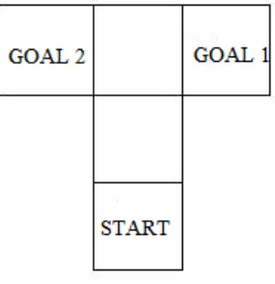
In this section, the movements of the mobile robot to achieve the goal to be tested in field trials in the form of floor 90 cm × 90 cm with a two-point goal, described through the Figure 11.
Fig. 11. Field test of the mobile robot movement.
The real field for testing will be shown as Figure 12 below.
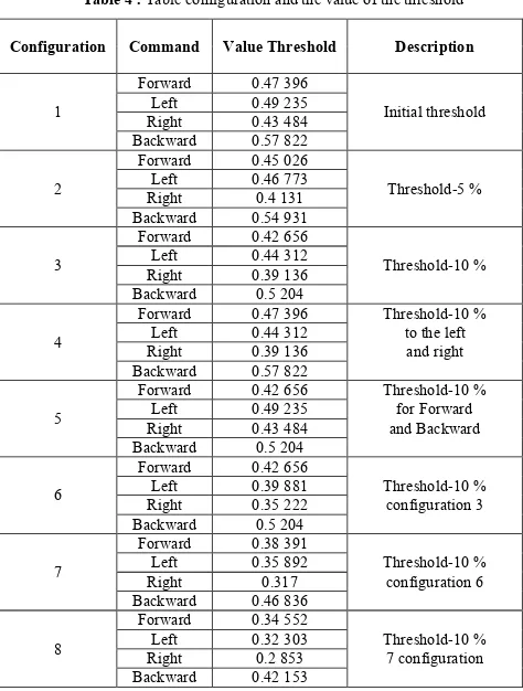
Through the configuration of threshold values, some set up have been configured to find the optimum threshold configuration. The configuration can be seen through the Table 4.
Table 4 . Table configuration and the value of the threshold
Configuration Command Value Threshold Description
1
Forward 0.47 396 Threshold-10 %
Left 0.44 312 to the left
Right 0.39 136 and right
Backward 0.57 822
5
Forward 0.42 656 Threshold-10 %
Left 0.49 235 for Forward
Right 0.35 222 configuration 3
Backward 0.5 204
7
Forward 0.38 391
Left 0.35 892 Threshold-10 %
Right 0.317 configuration 6
Backward 0.46 836
8
Forward 0.34 552
Left 0.32 303 Threshold-10 %
Right 0.2 853 7 configuration
Backward 0.42 153
On Table 4 which is a variation of the value of the threshold, threshold configuration in the early decline of as much as 5 %, 10 %, 10 % for left and right commands, 10 % for forward and backward commands, 10 % against configuration 3, 10 % against configuration 6, 10 % against configuration 7. It decreases gradually committed to see the response given by the car robot in achieving its purpose (reach goals). The results of the mobile robot in achieving the goal is shown as in Table 5 below.
Table 5 . Configuration testing time threshold
Based on the test results in Table 5, the test is performed five times, and the average time was obtained from tests on every configuration of threshold as shown in Table 6 below.
Table 6 . Average time of testing the configuration of threshold
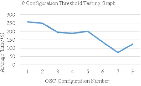
Representations of the test results through a graph can be seen in Figure 13 below.
Fig. 13. Threshold variation testing graph.
The results of the test that looks at the Table 6 and Figure 13, indicating the results of optimum threshold is configuration 7. On some previous configuration which have been done, decrement against the initial configuration stopped to the configuration 8, where time for mobile robot can reach a goal go back slower (125.066 s) than the configuration 7 (73.582 s).
4 Conclusion
The conclusion that can be drawn from the results of a study of control of movement of the mobile robot using EEG sensors Emotiv Epoc+ is that feature in command control can use facial expressions, rather than using the methods of thinking with the aid of visual or think without any assistance. With the use of various methods, it was obtained by facial expression 2 as a better method than the methods of facial expression 1, visual, or mind without assistance. The use of the first threshold values of a mobile robot can't make a robot move responsive, it took long enough time for the robot can move towards the goal (about 4 min). These factors caused configuration variations in the value of the threshold. The modification of the first threshold values generates 8 threshold configuration. From eight configurations, generate a configuration which is considered optimum because the average time the resulting car robot in achieve objectives on the test field. It is the configuration 7, which have the values of 0.38391 for forward command, 0.46836 for backward command, 0.35892 for left command, and also 0.31700 for right command.
References
1. E. Niedermeyer, F.H.L. da Silva. Electroencephalography: Basic principles, clinical applications, and related fields. Philadelphia: Lippincot Williams & Wilkins (2005). Pp. 17‒18.
https://books.google.co.id/books/about/Electroencephalography.html?id=tndqYGPHQdEC&redir_esc=y 2. M.E. Drake, H. Padamadan. S.A. Newell. Seizure, 7(1):39–42 (1998).
https://www.ncbi.nlm.nih.gov/pubmed/9548224
3. D. Huang, K. Qian, D.-Y. Fei, W. Jia, X. Chen, O. Bai. IEEE Trans. Neural Syst. Rehabil. Eng., 20(3):379–388 (2012). https://www.ncbi.nlm.nih.gov/pubmed/22498703
4. J. Svejda, R. Zak, R. Senkerik, R. Jasek. Using Brain - Computer Interface for Control Robot Movement. Cd.
5. A. Vourvopoulos, F. Liarokapis. Comput. Electr. Eng. 40(2):714–729 (2014). https://www.sciencedirect.com/science/article/pii/S0045790613002577
6. A.T. Campbell, T. Choudhury, S. Hu, H. Lu, M.K. Mukerjee, M. Rabbi, et al. NeuroPhone: Brain-mobile phone interface using a wireless EEG headset. Proceedings of the second ACM SIGCOMM workshop on Networking, systems, and applications on mobile handhelds-MobiHeld ‘10, pp 3–8 (New Delhi, India, 2010).
http://pac.cs.cornell.edu/pubs/neurophone.pdf
7. I.H. Parmonangan, J. Santoso, W. Budiharto, A.A.S. Gunawan. Fast brain control systems for electric wheelchair using support vector machine. Proceedings of SPIE, 10011:100111N (2016).
http://spie.org/Publications/Proceedings/Paper/10.1117/12.2243126
8. J. Lin, W. Yang. International Journal of Innovative Computing, Informaion and Control, 8(9):6011‒6024 (2012). http://www.ijicic.org/vol-8(9).htm