Compressive Strength of Post Fire Exposed Concrete Column
Wrapped with Fiber Reinforced Polymer
Wardaya, D.A.S.1, Sugiharto, H.2*, and Pudjisuryadi, P.2
Abstract: In this study, behaviour of reinforced concrete columns strengthened using fiber reinforced polymer (FRP; glass fiber and carbon fiber) after fire exposure are discussed. After being exposed to fire as high as 720oC for 180 minutes, the specimens showed concrete and
reinforcement strength degradation, even though there was no carbonation. It was found that specimens wrapped by carbon fiber showed better compressive strength but less ductility compared to specimens wrapped by glass fiber. It was also found that the low initial compressive strength did not decrease FRP confinement effectiveness. Increase of wrapped concrete com-pressive strength was evident despite the low initial strength (<17 MPa). Strength estimation using ACI 440.2R-08 formula, which is originally for wrapped plain concrete without fire heat exposure, underestimated the compressive strength. In the proposed formula, the initial
compressive strength (f’co) should be adjusted by considering the modulus elasticity and strain
limitation to have more precise estimation.
Keywords: Curing; fire exposed concrete column; fiber reinforced polymer.
Introduction
Research on the empirical formula for compressive strength estimation and behaviour of column confined using Fiber Reinforced Polymer (FRP) has been looked into extensively over the past two decades by many researchers. However most FRP confinement models [1-3] had been developed for FRP wrapped on concrete specimens with no expo-sure to fire. In Saafi’s et al. model [1], variables which influence the FRP wrapped compressive strength are unconfined compressive strength, failure strains, and FRP stress-strain relationship.
Saafi’s et al. [1] research was conducted on concrete-filled FRP tubes, tested under uniaxial compressive load with test variables include type of fiber, thick-ness of tube, and concrete compressive strength.
Lam and Teng [2] proposed simplified formula for concrete compressive strength with circular and square cross-section reinforced with FRP. The beha-vior of square concrete column wrapped with FRP is influenced by corner radius of the specimen [3]. There are different strains on the sides and the corners of the square cross-section [3].
1 Graduate Student, Department of Civil Engineering, Petra
Christian University, Jl. Siwalankerto 121-131, Surabaya 60236, INDONESIA.
2 Department of Civil Engineering, Petra Christian University, Jl.
Siwalankerto 121-131, Surabaya 60236, INDONESIA. *Corresponding author; Email: [email protected]
Note: Discussion is expected before November, 1st 2017, and will be
published in the “Civil Engineering Dimension”, volume 20, num-ber 1, March 2018.
Received 11 October 2016; revised 11 July 2017; accepted 17 August 2017.
Column size does not affect the strengthening behavior [3]. Lam and Teng [2] model was adopted by American Concrete Institute [4] as an empirical formula for FRP reinforcement design code.
FRP has also been used to strengthen post fire exposed concrete specimen [5]. Bisby et al. [5] suggested that the use of FRP in post fire exposed specimens would significantly increase (above 100 %) the compressive strength of the specimens. The model to estimate the compressive strength applies two assumptions: (1) the total increase in the ultimate stress is the same for the fire exposed and non-fire exposed concrete; and (2) the total increase in the ultimate axial strain between the strain at peak unconfined stress and the strain at peak FRP-confined stress is the same for the fire exposed and non-fire exposed concrete [5].
In this study, both concrete and reinforced concrete columns strengthened by FRP (glass fiber and carbon fiber) with two conditions (fire exposed and non-fire exposed) are presented. The effects of curing after exposure of fire were also investigated. An empirical formula for predicting FRP confined compressive strength of post fire exposure concrete column is proposed.
Experimental Work
Materials
The concrete mix proportion used for the research
was composed of 410 kg/m3 Portland Pozzolana
Cement (PPC), 673.6 kg/m3 sand, 1012.4 kg/m3 crush
strength was f’c 20 MPa. Concrete uniformity was
controlled by w/c ratio of 0.6, slump value with a range of 8-12cm, and also by Ultrasonic Pulse Velocity (UPV) test for 28 days concrete which
resulted in deviation ≤ 5% [6]. Mild steel reinforcing
bars with 4.4 mm diameter were used, both as longitudinal and transverse reinforcements. The tensile strength of reinforcements before (NF) and after fire exposure (F) of the specimen was tested and presented in Table 1. The mechanical properties of FRP used in the experiment is shown in Table 2. Standard epoxy adhesive was used for FRP applica-tion. For fire heat exposed specimens, should there were any spalled concrete covers, repair work was done by using patching material.
Table 1. Reinforcement Tensile Test
Code Dia. (mm) Yield (MPa) Ultimate (MPa)
NF 4.4 466.37 526.24
F 4.4 295.87 327.43
Table 2. FRP Specification
Property Carbon Fiber Glass Fiber Tensile Strength 834 MPa 460 MPa Tensile Modulus 82 GPa 20.9 GPa
Elongation at Break 1% 2.2%
Laminate Thickness 1 mm 1.3 mm
Design and Test of Specimens
The specimens used in this research were 100 x 100
x 300 mm3 columns (classified as short column with
slenderness ratio of 10.39 ≤ 22 according to SNI 03 -2847-2002 [7]). The longitudinal and transverse
reinforcement used were 4 – Ø4.4 mm and Ø4.4 mm
– 50 mm, respectively (in accordance with SNI 03-2847-2002 [7]). The column detail is shown in Figure 1. The uniformity and quality of FRP application was done according to standards by TYFO (FRP applicator). To decrease ineffective area, the speci-men corner was rounded (r = 10mm). FRP was applied fully to lateral area of the specimen. FRP application process is shown in Figure 2.
Figure 1. Column Dimensions and Detail
Figure 2. FRP Application Process
The specimen variables were reinforcement, fire exposure, curing after fire exposure, and wrapping material. The specimens were casted with and with-out reinforcement. Half of the specimens were
expos-ed to fire at 720oC for 180 minutes in accordance to
SNI 03-1736-2000 [8]. The fire exposure process uniformity was checked by carbonation test result. All fire heat exposed specimens showed the same
color after tested by 1% phenolphthalein (PP), which
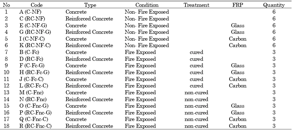
means that all specimens experienced uniform combustion temperatures [6]. Some of the fire expos-ed specimens were curexpos-ed using water for 3 days. Glass and carbon fibers were used for strengthening. With the mentioned variations, for easiness of identification, specimens’ codes are listed as shown in Table 3.
Universal testing machine (UTM) was used to con-duct the concentric compressive test. From the recorded specimen load resistance and displacement during the test, the axial stress-strain curve could be generated for each specimen.
Test Result
Effect of Transverse Reinforcement and Fire Heat Exposure
The test results show that concrete specimens (C-NF) and reinforced concrete specimens (RC-(C-NF) have the same compressive strength. The compres-sive strength is shown in Figure 3. The same com-pressive strength showed that the transverse rein-forcement had no effect. The distance between transverse reinforcement was 50 mm (H/2), so there was a concrete core that had no lateral confining pressure [7].
Figure 4 shows that concrete specimens exposed to
high temperature at 720oC experienced strength
Figure 3. Stress-Strain Curve of Plain Concrete and Reinforced Concrete in Non-Fire Exposed Condition
Figure 4. Stress-Strain Curve of Plain Concrete specimens
in Non-Fire Exposed, Fire Exposed-Cured, and Fire Exposed Non-cured Conditions
Specimens Confined by Fiber Reinforced Poly-mer
The stress-strain curve of concrete specimens strengthen with FRP (glass fiber–carbon fiber) in
Non-Fire Exposed condition is shown in Figure 5. The stress-strain curve of reinforced concrete
speci-mens strengthen with FRP (glass fiber–carbon fiber)
in non-fire exposed condition is shown in Figure 6.
Figure 5. Stress-Strain Curve of Concrete Specimens
Strengthen with FRP in Non-Fire Exposed Condition
Figure 6. Stress-Strain Curve of Reinforced Concrete Specimens Strengthen with FRP in Non-fire Exposed Condition
The stress-strain curve of concrete specimens streng-then with FRP (glass fiber – carbon fiber) in fire exposed condition with curing treatment is shown in Figure 7. The stress-strain curve of reinforced
Table 3. Specimens Code, Variation and Quantity
No Code Type Condition Treatment FRP Quantity
1 A (C-NF) Concrete Non- Fire Exposed 6
2 C (RC-NF) Reinforced Concrete Non- Fire Exposed 6
3 E (C-NF-G) Concrete Non- Fire Exposed Glass 6
4 G (RC-NF-G) Reinforced Concrete Non- Fire Exposed Glass 6
5 I (C-NF-C) Concrete Non- Fire Exposed Carbon 6
6 K (RC-NF-C) Reinforced Concrete Non- Fire Exposed Carbon 6
7 B (C-Fc) Concrete Fire Exposed cured 3
8 D (RC-Fc) Reinforced Concrete Fire Exposed cured 3
9 F (C-Fc-G) Concrete Fire Exposed cured Glass 3
10 H (RC-Fc-G) Reinforced Concrete Fire Exposed cured Glass 3
11 J (C-Fc-C) Concrete Fire Exposed cured Carbon 3
12 L (RC-Fc-C) Reinforced Concrete Fire Exposed cured Carbon 3
13 M (C-Fnc) Concrete Fire Exposed non-cured 3
14 N (RC-Fnc) Reinforced Concrete Fire Exposed non-cured 3
15 O (C-Fnc-G) Concrete Fire Exposed non-cured Glass 3
16 P (RC-Fnc-G) Reinforced Concrete Fire Exposed non-cured Glass 3
17 Q (C-Fnc-C) Concrete Fire Exposed non-cured Carbon 3
concrete specimens strengthen with FRP (glass fiber
– carbon fiber) in fire exposed condition with curing
treatment is shown in Figure 8.
Figure 7. Stress-Strain Curve of Concrete Specimens
Reinforced with FRP in Fire Exposed-cured Condition
Figure 8. Stress-Strain Curve of Reinforced Concrete Specimens Reinforced with FRP in Fire Exposed-cured Condition
The stress-strain curve of concrete specimens strengthen with FRP (glass fiber and carbon fiber) in fire exposed condition without curing treatment is shown in Figure 9. The stress-strain curve of rein-forced concrete specimens strengthen with FRP (glass fiber and carbon fiber) in fire exposed condi-tion without curing treatment is shown in Figure 10.
Figure 9. Stress-Strain Curve of Concrete Specimens
Reinforced with FRP in Fire Exposed Non-Cured Condition
Figure 10. Stress-Strain Curve of Reinforced Concrete Specimens Reinforced with FRP in Fire Exposed Non-Cured Condition
Based on the stress-strain curve of all specimens variation, specimens strengthened by carbon fiber showed better compressive strength than specimens strengthened by glass fiber, but had more brittle failure mechanism. The low initial strength of speci-mens did not reduce the effectiveness of FRP con-finement.
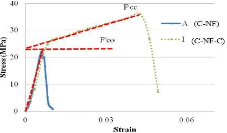
Stress-Strain Model
Lam and Teng [2] empirical model was used as reference in this study, because the model is used in ACI 440.2R-08 [4] for FRP design. In this study, it was found that stress strain curve of plain concrete strengthen with FRP (glass fiber–carbon fiber) in non-fire exposed condition was well predicted by the model. The model of plain concrete in non-fire exposed condition is shown by the straight dashed line and the experimental result is shown by the curve dotted line in Figure 11.
Figure 11. Stress-Strain Curve of Plain Concrete in
Non-Fire Exposed Condition Reinforced with FRP
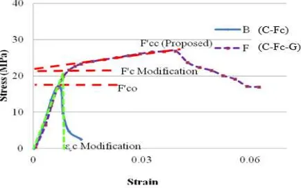
However, the ACI 440.2R-08 model cannot directly be applied to predict the stress-strain curve of reinforced concrete specimens and stress-strain curve of specimens in fire exposed condition with or without curing treatment. It was found that a slight modification in the model is necessary for stress-strain prediction of specimens with such conditions. The difference between ACI 400.2R-08 model and stress-strain experimental curve is shown in Figure
For reinforced concrete specimens and specimens in fire exposed condition had difference elastic modulus with plain concrete in non-fire exposed condition. The difference of elastic modulus caused a “gap”
between the initial specimen’s compressive strength
and the stress before the transition point. The gap caused the calculation based on ACI 440.2R-08 underestimate the compressive strength. The propos-ed model adjusted the f’co and is shown in Figure 13.
Figure 12. ACI Stress-Strain Curve Model for Reinforced
Concrete Specimens and Specimens in Fire Exposed Condition
Figure 13. Proposed Stress-Strain Curve Model for Reinforc-ed Concrete Specimens and Specimens in Fire ExposReinforc-ed Condition
Figure 14. Fire exposed-Cured Plain Concrete Elastic Modulus Curve
To reduce the gap, modification on the f’co become
f’c modification is needed. f’c modification is obtained from
considering specimen’s elastic modulus and the
strain limitation. Specimen’s elastic modulus was
different for each variation. Example of Specimen’s elastic modulus graph is shown in Figure 14. Specimen’s elastic modulus and strain limitation for each variation are shown in Table 4.
Table 4. Strain Limitation of Reinforced Concrete Speci-mens and Fire Exposed SpeciSpeci-mens
Specimen Code
E (MPa)
f’co
(MPa)
f’c modification
(MPa)
ᶓc Modification
G (RC-NF-G) 3714 22.16 30.71 0.0082 K (RC-NF-C) 3714 22.16 27.64 0.0074 F (C-Fc-G) 2608 17.16 18.81 0.0071 H (RC-Fc-G) 2166 17.78 22.85 0.0105 J (C-Fc-C) 2608 17.16 18.81 0.0071 L (RC-Fc-C) 2166 17.78 22.71 0.0104 O (C-Fnc-G) 1195 5.79 15.81 0.0131 P (RC-Fnc-G) 1751 11.84 22.12 0.0125 Q (C-Fnc-C) 1195 5.79 15.81 0.0131 R (RC-Fnc-C) 1751 11.84 16.79 0.0095
Table 5. Comparison between ACI Model Estimation and Proposed Model Estimation
No Specimen Code
Age (days)
Experimental Strength (MPa)
Strength Enhancement (%)
ACI Model Estimation (MPa)
Error (%)
Proposed Model Estimation (Mpa)
Error (%)
1 A (C-NF) 51 22.04
Control Specimen 2 C (RC-NF) 52 22.16
3 E (C-NF-G) 48 30.76 40% 31.42 2.16% 30.95 0.62%
4 G (RC-NF-G) 49 39.14 77% 33.60 -14.16% 39.58 1.12%
5 I (C-NF-C) 45 36.02 63% 36.35 0.93% 34.26 -4.89%
6 K (RC-NF-C) 43 39.14 77% 38.49 -1.65% 39.80 1.69%
7 B (C-Fc) 61 17.16 Control Specimen
8 D (RC-Fc) 62 17.78
9 F (C-Fc-G) 60 26.81 56% 22.59 -15.72% 27.06 0.94%
10 H (RC-Fc-G) 56 31.27 76% 23.96 -23.38% 31.07 -0.64%
11 J (C-Fc-C) 57 30.33 77% 28.81 -5.02% 30.13 -0.66%
12 L (RC-Fc-C) 54 33.75 90% 30.12 -10.74% 33.98 0.70%
13 M (C-Fnc) 61 5.79
Control Specimen 14 N (RC-Fnc) 62 11.84
15 O (C-Fnc-G) 60 24.24 319% 11.13 -54.10% 24.81 2.33%
16 P (RC-Fnc-G) 56 30.85 161% 12.55 -59.32% 31.08 0.74%
17 Q (C-Fnc-C) 57 29.22 404% 17.34 -40.66% 28.15 -3.65%
The proposed model is more precise than the ACI 440.2R-08 model. In other word, the estimation is more efficient. The comparison between the ACI model estimation and proposed model estimation is shown in Table 5.
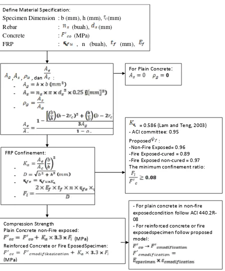
Proposed flow chart calculations of column streng-then by FRP various conditions are shown in Figure 15. For axial capacity design, shear strength safety factor (0.65) needs to be used because the increased compressive strength was the effect of FRP confine-ment.
Figure 15. Compression Strength Calculation Flow Chart
for Rectangular Column Confined by FRP
Conclusion
In this paper, ACI 440.2R-08 model has been eva-luated and reviewed, using test on plain concrete specimens and reinforced concrete specimens in various condition (non-fire exposed, fire exposed-cured, and fire exposed non-cured). Based on the test results of the study, the following conclusions can be drawn:
1. Specimens strengthen by carbon fiber showed better compressive strength than specimens strengthen by glass fiber but had more brittle pattern.
2. Specimens in fire exposed condition with or with-out curing process has low initial compressive strength (<17 MPa) and various collapse pattern, but it did not reduce FRP confinement effec-tiveness. The compressive strength of specimens with low initial compressive strength strengthens by FRP was significantly increased (Figures 7-10).
3. Estimation of compressive strength using ACI 440.2R-08 model is appropriate for plain concrete specimens in non-fire exposed condition (Figure 11).
4. Reinforced concrete, fire exposed concrete, and fire exposed reinforced concrete had different elastic modulus with non fire exposed concrete.
Gap between specimen’s initial strength and the transition point was caused by the difference elastic modulus. The compressive strength was underestimated by ACI 440.2R-08 model (Figure 12).
5. For efficiency, modification (Figure 13) on the f’co
become f’c modificationis needed. f’c modification is obtained
by considering specimen’s elastic modulus and
the strain limitation (cmodification).
6. Proposed model generates closer compressive strength estimation to the compressive test result, with maximum error -4.89% for all specimens (Table 5).
References
1. Saafi, M., Toutanji H., and Li, Z., Behavior of Concrete Columns Confined with Fiber
Reinfor-ced Polymer Tubes, ACI Materials Journal, 96(4),
1999, pp. 500-509.
2. Lam, L. and Teng, J.G., Design-oriented Stress–
Strain Model, Journal of Reinforced Plastics and
Composites, 22(13), 2003, pp. 1149–1186.
3. Lee, C.S., Hegemier, G.A., and Phillippi, D.J., Analytical Model for Fiber-Reinforced Polymer-Jacketed Square Concrete Columns in Axial
Compression, ACI Structural Journal, 107(2),
2010, pp. 208–217.
4. ACI 440.2R-08, Guide for the Design and
Con-struction of Externally Bonded FRP Systems for
Strengthening Concrete Structures, American
Concrete Institute, 2008.
5. Bisby, L.A., Chen, J.F., Li, S.Q., Stratford, T.J., Cueva, N., and Crossling, K., Strengthening Fire-Damaged Concrete by Confinement with
Fiber-Reinforced Polymer Wraps, Engineering
Struc-tures, 33(12), 2011, pp. 3381–3391.
6. Wardaya, D.A.S., Analisa Rumus Empiris Kuat
Tekan Kolom dengan Penggunaan Fiber
Reinfor-ced Polymer pada Kondisi: Non-Fire exposed, Fire
exposed-Curing, dan Fire exposed Non-Curing,
Unpublished Graduate Theses, Petra Christian University, 2016.
7. Badan Standarisasi Nasional, SNI 03-2847-2002:
Tata Cara Perhitungan Struktur Beton Untuk
Bangunan Gedung, 2002.
8. Badan Standarisasi Nasional, SNI 03-1736-2000:
Tata Cara Perencanaan Sistem Proteksi Pasif Untuk Pencegahan Bahaya Kebakaran pada
Bangunan Rumah dan Gedung, 2000.
Define Material Specification: -Fire Exposed non-cured = 0.97 The minimum confinement ratio:
Compression Strength Plain Concrete non-Fire exposed:
(MPa) Reinforced Concrete or Fire EposedSpecimen:
(MPa)
- For plain concrete in non-fire exposedcondition follow ACI 440.2R-08
![Figure 4 shows that concrete specimens exposed to high temperature at 720oC experienced strength degradation even though there was no carbonation process [6]](https://thumb-ap.123doks.com/thumbv2/123dok/1566256.2050829/2.595.57.277.614.766/figure-concrete-specimens-temperature-experienced-strength-degradation-carbonation.webp)