Copyright @2017, JNSMR, ISSN: 2460-4453
Available online at http://journal.walisongo.ac.id/index.php/jnsmr
Car Robots of Line Followers and False Detections Using Microcontroller
of BS2SX Basics Tamp
Sujarwoto
Department of Physics, Faculty of Mathematics and Natural Science, Semarang State University (UNNES), Central Java.Indonesia
Corresponding author: [email protected]. id
Recived: 15 April 2017, Revised : 17 May 2017 Accepted: 20 June 2017.
Abstracts
This study aims to design a robot car that can follow the line and can avoid obstacles if it detects objects. The movement of the robot car is equipped with light sensor (LDR) and ultrasonic as its navigation system. Automation system navigation settings using BS2SX Basic Stamp microcontroller hardware, while the software with Pbasic programming language. The program is written on the Basic Stamp Editor already installed on the PC, then downloaded to EEPROM. Ultrasonic sensors are utilized as a detection of obstacles and light sensor sensors (LDR) as a tracked line detector. The robot will follow the designed line, if there are obstacles in front of it the robot will avoid and run back if the ultrasonic sensor does not detect obstacles in front of it. With the PWM signal input setting (Pulse Width Modulation) from the microcontroller, the robot car can walk straight, turn and will avoid when detecting obstacles. ©2017 JNSMR UIN Walisongo. All rights reserved
Key words: BS2SX , EEPROM, PWM, Robots; Sensor.
1.
Introduction
The development of the field of electrical engineering is very wide and rapidly at this time, especially in the manufacture and design of robots, various competitions held to pit the level of technology owned. From just a hobby until the robot industry is never used up-robot car especially in the industrial world is needed for the efficiency of a job that can save the cost of a production. In addition, robot cars are also
Copyright @2017, JNSMR, ISSN: 2460-4453 hitch still exists and run again if the ultrasonic
sensor does not detect a hitch in front of it. The robot car in this research uses Basic Stamp BS2SX microcontroller made by Parallax Inc, USA, in the form of IC PIC16C65. While the software uses Pbasic programming language. In addition to walking the wheeled robot follower trajectory that has been determined and can detect obstacles in front. LDR applications in this study used two LDR mounted on the robot car. The use of LDR fruit in research is not to measure the intensity of light around the robot car, but rather compare the intensity received by the LDR. If the intensity received by the right LDR and the left LDR is different, then the robot car will provide a specific movement response according to the command through the program [2]. Examples of LDR applications are mounted on robot cars to provide specific movement responses and can traverse the
predetermined path through Pbasic
programming [3].
Problems that arise in this robotic system is how to assemble and install the right sensors so that the robot can make moves in accordance with the command. Installation of the sensor as a robot car sensors requires a separate technique with respect to the characteristics, position of sensors and objects detected. For example installation Ultrasonic wave sensor on the wheeled robot must know the specification of the sensor [4], put the sensor and the position of the detected object.
In this study, the wheeled robot (robot wheel/robotic car) is equipped with ultrasonic sensors to detect objects and avoid collisions. The wheeled robot moves actively in a controlled manner on a particular trajectory due to a drive with its regulating system. Therefore it is necessary to understand the field of science related to the robot as a whole. The field of science is: a) kinematics is a field of science that studies the geometry of the robot movement with no attention to the style of the robot, b) dynamics is a field of science that learns about the force as the cause of wheeled robot can move, c) control system The field of science that studies the way the robot moves in a controlled manner, d) the sensor of science is needed so that the robot can sense
what happens to himself and his environment, e) navigation is a field of science needed especially for robot cars in order to determine the direction of the road so it can arrive on the spot Goals with the correct orientation position, and f) the computer, where this field of knowledge needs to be mastered because of the components that make the brain in the activity.
The keywords underlying the world of robotics are regulatory systems. Because the robot must eventually move in a controlled way to a predetermined position, whether it is controlled by humans, themselves or by other robots. One reason for the use of ultrasonic waves is to have short wavelengths, smaller diffraction and more incomplete waveforms, so that smaller objects can be detected [5,6]. If the ultrasonic wavelength is less than the size of the object blocking the wave propagation, the object will reflect a considerable portion of the wave. The smallest object that can be detected is in the wavelength order used [6]. By utilizing higher ultrasonic wave frequencies, smaller objects can be detected.
2.
Experiments Procedure
The design of this research is based on 2 parts, namely the design of hardware and software design. The design of hardware in the form of preparation of components, so it becomes a unity of circuit systems that can work as expected. The design of software in the form of programming language that makes the system can work in accordance with the workings of the tool.
Copyright @2017, JNSMR, ISSN: 2460-4453 avoid obstacles, microcontroller programming
and robotics programming.
Writing programming, used Basic Stamp Editor that has been installed previously on the PC. After writing the program, the PC is connected to Basic Stamp Microcontroller [1]. Basic Stamp Microcontroller is connected with battery supply. Press Run on Basic Stamp Editor to download the program to EEPROM. The program download process automatically deletes the previous program and the microcontroller will execute the last program.
Programming requirements are as follows: programs that have been written in the Basic Stamp Editor are then stored in BS2SX [8] * format, then the programs that have been saved in BS2SX * format will be modified during the download process into binary format which can be read by microcontroller using interpreter in Basic Stamp, comment "Tokenzied is successfully" will appear when the Pbasic program has been successful. To reprogram Basic Stamp just by connecting PC, then run Basic Stamp Editor, then press Alt-R or RUN [9]. Steps in robotic car research, including: collection of materials and tools, plotting controlled servo motor controlled, assembling wheeled robot, PCB design for ultrasonic sensors, installing sensors on wheeled robots to be controlled as needed and finally testing on robotic cars.
3.
Result and Discussion
Ultrasonic wave sensor is a sensor that can convert physical quantity (sound) into electricity. In this sensor ultrasonic waves are generated through an object called piezoelectric. This piezoelectric will produce ultrasonic waves with a frequency of 40 kHz when an oscillator is applied to the object. Ultrasonic sensors are generally used for a variety of non-touch disclosures such as distance measurement applications. This tool generally transmits ultrasonic sound waves to a target that reflects back the wave towards the sensor. Then the system measures the time it takes to wave the waveform back to censor and calculate the target distance using the
speed of sound in the medium. This ultrasonic wave sensor compilation circuit consists of transmitter, reiceiver, and comparator. In addition, ultrasonic waves are generated by a thin piezoelectric crystal.
The ultrasonic wave used for measurement is a wave with a frequency of 50 kHz. If the speed of the sound wave v (v) is 332 smallest object detected by the ultrasonic sensor [7,11]. Thus, the larger the frequency used the smaller the size of the object can be detected. While the distance between the receiver and the ultrasonic transmitter determines the furthest distance the object can detect by ultrasonic sensors. Special elastic waves that have frequencies with frequencies above 20,000 Hz are called ultrasonic waves. The science of learning how to manufacture sound sources, propagation and processing in a medium is called acoustics [7]. To facilitate the analysis of acoustic waves, it is worth noting that the direction of the waves that go to the receiver in one dimension. Surface wave surfaces are described in one dimension as shown in (Figure 1.)
Figure 1. Ultrasonic detector [12]
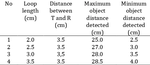
Copyright @2017, JNSMR, ISSN: 2460-4453 test used the object size and distance between transmitter and ultrasonic wave receiver the same, that is 3.5 cm. From the results of tests detected is 0.5 cm, while the distance Furthest 28.5 cm, an object that forms an angle of 00 to drive the wheeled robot, as follows: left wheel forward movement is given the number of pulses> 1600 pulses and the wheel can provide the number of pulses <1650 pulses, backward motion, left wheel is given the number of pulses <1600 pulses and the right wheel is given Number of pulses> 1650 pulses, turn right, left wheel is given the number of pulses> 1600 pulses and the right wheel is given the number of pulses = 1650 pulses, turn left, left wheel given the number of pulses = 1600 pulses and the right wheel is given the number of pulses <1650 pulses.
The above test results can be applied to the robot car movement to avoid collision. To possibilities, among others: the size and shape of the object, the position of the object and how to install ultrasonic sensors. Therefore, when installing ultrasonic sensors on the robot car to note the location. In contrast, the ultrasonic receiving sensor receives waves rather than reflective waves from the object so it responds even when no object exists. This happens because the ultrasonic wave sensor receives the transmitted wave from the ultrasonic wave transmitter. This can be overcome by installing a loop (sleeve) on the ultrasonic wave sensor so that the receiver will receive only reflected waves only.
Copyright @2017, JNSMR, ISSN: 2460-4453
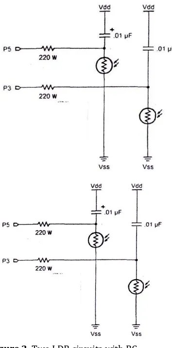
Figure 2. Two LDR circuits with RC
The two LDR circuits with the RC shown in (Figure 2) are designed for use in PBasic programming commands (parallax Basic). This command can be used in RC circuits, where any value of R (Resistor) or C (Capasitor) has a constant value. The unutu time command of RC is used to measure the value variable, because it has the advantage of a time varying RC circuits. The voltage in the RC circuit changes depending on the product of R and C. RC is a constant which has a constant value and is characterized by a tau symbol (τRC).
Light sensor applications (LDR) utilized by the author in this study used two LDR mounted on the robot car to follow a particular trajectory. The use of 2 LDRs in the author's research is not to measure the intensity of light around the robot car, but to compare the intensity received by the LDR. If the intensity received by the right LDR and the left LDR is different, then the robot car will provide a specific movement response according to the command through the program. Examples of LDR applications (light sensors) mounted on robot cars to provide specific movement responses with commands via Pbasic programming (see Tabel 2).
Tabel. 2. Program. Movement of robot car (robot wheel) using 2 pieces of LDR.
__________________________________________________________________________
' Define Variables and Constanta
__________________________________________________________________________
right servo
Con 12 '
P12 sebagai servo kanan
left servo
Con 13 '
P12 sebagai servo kiri
turnvalue
Con 6
scale
Con 100
speed
Con 100
speaker
Con 2
rightLDR
Var word
leftLDR
Var word
x
Var word
white
Con 1
black
Con 0
---
Main Program
Copyright @2017, JNSMR, ISSN: 2460-4453
Pulsout left servo, 1600 + speed
Pulsout right servo, 1650 + speed
pause 20 next
right light
high 3
pause 10
rctime 3,1,rightLDR
debug " R ",dec rightLDR
freqout speaker,100,rightLDR*scale +100
left light
high 5
pause 10
rctime 5,1,rightLDR
debug " L ",dec rightLDR
freqout speaker,100,leftLDR*scale +10
if rightLDR = while and leftLDR = black then left
if leftLDR = while and rightLDR = black then right
if leftLDR = while and rightLDR = black then backward
right :
high 0
for x = 1 to turnvalue
Pulsout left servo, 1600 + speed
Pulsout right servo, 1650 + speed
pause 20
next
low 0
left :
high 0
for x = 1 to turnvalue
Pulsout left servo, 1600 + speed
Pulsout right servo, 1650 + speed
pause 20
next
low 0
goto forward
backward :
high 0
for x = 1 to turnvalue
Pulsout left servo, 1600 + speed
Pulsout right servo, 1650 + speed
pause 20
next
low 0
goto forward
Copyright @2017, JNSMR, ISSN: 2460-4453
Program command for RC time
measurements on pin I / O P3, starting from the voltage condition 1 V or 5 V and the results stored in right photo variable (right photoresistor). Remember that the value stored on the right photoresistor is a number. The figure describes the addition of 2 s to the low voltage of the capacitor. Pin I/O capacitors at low voltage conditions (1.4 V) and meruapakan threshold voltage.
high 3 pause
rctime 3, 1 right photo
4.
Conclusion
The
ultrasonic wave sensor has the
radiating and receiving properties of
ultrasonic wave reflection that can be used
to detect objects. In order for the reflection
of ultrasonic waves from the object to be
able to reach the receiver, it is necessary to
set the position between the transmitting
and transmitting sensors. By precisely
placing the ultrasonic wave sensor, the
detected object can be distinguished and
known for its position. The use of 2 pieces
of LDR (light sensor) in this research is not
to measure the intensity of light around the
robot car, but to compare the intensity
received by the LDR. If the intensity
received by the right LDR and the left LDR
is different, then the robot car will provide
a specific movement response according to
the command through the program.
Acknowledgment
The authors wish to thank Department of Physics, Semarang State University for supporting this work.
References
[1] Sujarwata, Pengendali Motor Servo Berbasis Mikrokontroler Basic Stamp 2SX Untuk Mengembangkan Sistem Robotika, JURNAL ANGKASA, Vol.V/ No.1. 2013.
[2] S. Hali, Merancang Mobile Robot Pembawa Objek Menggunakan OOPic-R, Elexmedia Komputindo : Jakarta, 2007.
[3] Sujarwata, Belajar Mikrokontroler PICI6C57
Dengan Bahasa Pemrogaman Pbasic,
Deepublish (CV Budi Utama) Yogyakarta, 2016.
[4] Sujarwata, Teknik Pemasangan Sensor Gelombang Ultrasonik Pada Robot Beroda Untuk Menghindari Benturan. Thesis, 2003. [5] M. Alonso. Dasar-dasar Fisika Universitas.
Erlangga: Jakarta, 1992.
[6] Agfianto. Belajar mikrokontroler AT89C51/52/53 (Teori dan Aplikasinya). Penerbit Gava Media.Yogyakarta, 2002. [7] M.O.Tjia, Gelombang, Dabara Publishers.
Solo. 1994,
[[8] Sujarwata, Belajar Mikokontroler BS2SX
(Teori, Penerapan dan Contoh
Pemrograman PBasic), Deepublish (CV Budi Utama) Yogyakarta. 2013.
[9] J.J. Corr, and N Sors, Transducers, and Supporting Circuit For Electronics
Instrumentation Measurement and
Control.Prentice. Hall. Inc. Englewood Cliffs. New Jersey 07632.USA. 1993.
[10] D.C. Giancolli, Fisika. Edisi Kelima. Erlangga. Jakarta, 2001.
[11] Sutrrisno. Elektronika Lanjutan. Dikat kuliah Fisika ITB. Bandung.kedua. Alih bahasa Sutisna. Penerbt Erlangga. Jakarta, 1987.
![Figure 1. Ultrasonic detector [12]](https://thumb-ap.123doks.com/thumbv2/123dok/1896947.1586639/3.612.315.548.483.619/figure-ultrasonic-detector.webp)