Date: 2011-07-08
Reference number of this document: OGC 11-058r1
Category: OGC Discussion Paper
Editor:Ingo Simonis, Chrsitian Malewski
*FL Starfish Fungus Language for Sensor Description
Copyright © 2011 Open Geospatial Consortium
To obtain additional rights of use, visit http://www.opengeospatial.org/legal/.
Warning
This document is not an OGC Standard. This document is an OGC Discussion Paper and is therefore not an official position of the OGC membership. It is
distributed for review and comment. It is subject to change without notice and may not be referred to as an OGC Standard. Further, an OGC Discussion Paper should not be referenced as required or mandatory technology in procurements.
Document type: OpenGIS® Discussion Paper
Document subtype: NA
Document stage: Public
ii Copyright © 2011 Open Geospatial Consortiu
Preface
This is an OGC Discussion Paper for review by OGC members and other interested parties. This is a working draft document and may be updated, replaced by other documents at any time. It is inappropriate to use OGC Discussion Papers as reference material or to cite them as other than “work in progress.” This is work in progress and does not imply endorsement by the OGC membership.
10.3.3 ConformanceGroup ... 23
. . . label ... . . . . . . type ... test ... XAMPLE ENSOR ACTERISTIC MIDDLETON PYRANOMET . E : S CHAR ER ... . EXAMPLE: SENSOR CHARACTERISTIC VAISALA WXT WEATHER STATION ... . EXAMPLE: SENSOR DEPLOYMENT MIDDLETON PYRANOMETER ...
Figures
Page Figure 1: Starfish Fungus, Canberra, Australia ... 5Figure 2: Common module ... 7
Figure 3: Static Module... 10
Figure 4: Composite pattern of the static module ... 11
Figure 5: Vaisala 520 weather station ... 11
Figure 6: Static module ... 12
Figure 7: MeasurementCapability ... 14
Figure 8: Major blocks of the dynamic module ... 16
Figure 9: Dynamic Module ... 16
Figure 10: Sensor related classes of dynamic modules ... 17
Figure 11: Deployment and platform types ... 19
Figure 12: Calibration and conformance types ... 22
Listings
Page Listing 1: Ex-factory description of a digital humidity sensor ... 6Listing 2: Deployed sensors simply references the ex-factory description ... 7
Listing 3: Example of ConditionalValue ... 8
Listing 4: Example of ComplexConditionalValue ... 9
Listing 5: Sensor characterisitic of a Middleton pyranometer ... 24
Listing 6: SensorCharacteristic of a Vaisala WXT 520 Weather Station ... 26
*FL Starfish Fungus Language for Sensor Description
1 Introduction
1.1 Scope
The Starfish Fungus Language was developed in response to the high number of complaints addressing issues with the OGC standard Sensor Model Language, SensorML. Most complaints circled around the high flexibility of the language in combination with unnecessary abstractions of technical terms, e.g. every sensor is not a sensor but a process. Most beginners struggled with the composite pattern of those processes, as there is no well-defined rule what needs to be described where. As a beginner, it is almost impossible to write a simple sensor description without getting major guidance through the SensorML development team or other experts.
Starfish Fungus Language, *FL, builds on those experiences. It implements the Pareto principle and thus does not try to support every imaginable sensor/platform
constellation, but concentrates on those requirements typically given in our inter-viewed target domains hydrology, disaster management, and fabrication. *FL sup-ports every type of sensor and allows expressing all details about the sensing procedures implemented by the various hard- and software components of a sensor; but cuts back on sensor and sensor to platform orientation aspects. *FL is used to describe sensor properties, capabilities, and corresponding deployment aspects, but is not intended to be ingested in processing frameworks performing on the fly geo-localization of incoming video material from wobbling UAVs.
Attention is drawn to the possibility that some of the elements of this document may be the subject of patent rights. The Open Geospatial Consortium Inc. shall not be held responsible for identifying any or all such patent rights.
Recipients of this document are requested to submit, with their comments, notification of any relevant patent claims or other intellectual property rights of which they may be aware that might be infringed by any implementation of the standard set forth in this document, and to provide supporting documentation.
1.2 Document contributor contact points
All questions regarding this document should be directed to the editor or the contributors:
Name Organization
Ingo Simonis iGSI GmbH
Christian Malewski University of Muenster
Andrew Terhorst CSIRO Tasmanian ICT Centre
2 Copyright © 2011 Open Geospatial Consortium
Simon Cox CSIRO Perth
1.3 Revision history
Date Release Editor Primary clauses
modified
Description
2011-06-11 1.0 Ingo
Simonis
All Initial version
2011-06-11 1.0.1 Ingo
Simonis
div. Comments and review from C. Malewski
worked in.
1.4 Future work
This document serves as a base for discussion and will be further developed in all parts.
1.5 Forward
Attention is drawn to the possibility that some of the elements of this document may be the subject of patent rights. The Open Geospatial Consortium shall not be held responsible for identifying any or all such patent rights.
Recipients of this document are requested to submit, with their comments, notification of any relevant patent claims or other intellectual property rights of which they may be aware that might be infringed by any implementation of the standard set forth in this document, and to provide supporting documentation.
2 References
The following documents are referenced in this document. For dated references, subsequent amendments to, or revisions of, any of these publications do not apply. For undated references, the latest edition of the normative document referred to applies.
[Golodoniuc2010] Golodoniuc, P. & Cox, S. Application schema modeling for
[Seegrid2011a] https://www.seegrid.csiro.au/wiki/AppSchemas/HollowWorld
[Seegrid2011b] https://www.seegrid.csiro.au/wiki/AppSchemas/FullMoon
[Robin2011] Robin, A. (ed.) OGC SWE Common Data Model Encoding
Standard v2.0. OGC Document 08-094r1
[W3C2011] http://www.w3.org/2005/Incubator/ssn
OGC 06-121r3, OpenGIS® Web Services Common Standard
NOTE This OWS Common Specification contains a list of normative references that are also applicable to this Implementation Specification.
3 Terms and definitions
For the purposes of this report, the definitions specified in Clause 4 of the OWS
Common Implementation Specification [OGC 06-121r3] and in OpenGIS® Abstract
Specifications shall apply.
4 Conventions
4.1 Abbreviated terms
O&M Observation and Measurement
SensorML Sensor Model Language
SWE Sensor Web Enablement
4.2 UML notation
Most diagrams that appear in this standard are presented using the Unified Modeling Language (UML) static structure diagram, as described in Subclause 5.2 of [OGC 06-121r3].
4.3 Used parts of other documents
none
5 Introduction
4 Copyright © 2011 Open Geospatial Consortium
Starfish Fungus Language, *FL, builds on those experiences. It implements the Pareto
principle1 and thus does not try to support every imaginable sensor/platform
constellation, but concentrates on those requirements typically given in our inter-viewed target domains hydrology, disaster management, and fabrication. *FL sup-ports every type of sensor and allows expressing all details about the sensing procedures implemented by the various hard- and software components of a sensor; but cuts back on sensor and sensor to platform orientation aspects. *FL is used to describe sensor properties, capabilities, and corresponding deployment aspects, but is not intended to be ingested in processing frameworks performing on the fly geo-localization of incoming video material from wobbling UAVs.
As a major difference to SensorML, *FL features a clear separation between the physical device (Sensor), its model specific composition (SensorCharacteristics), and the specific procedures running on a physical device or subcomponents respectively (SensingProcedure). By this, it follows its main conceptual ancestor, the sensor ontology developed by the W3C Semantic Sensor Network Incubator Group [W3C2011]. The semantic sensor network (SSN) ontology was developed with the goal to apply semantic web technologies to the Sensor Web, i.e. to align SensorML, O&M, and lately even foundational ontologies. It describes where a given sensor fits in the world of sensors and sensing, i.e. focuses on an ontology in which sensor types and instances can be specified to allow reasoning to infer relationships and
hierarchies. Unfortunately, one of the latest actions before closing the incubator group was the alignment of the formerly promising SSN ontology with the ultra light
version of the DOLCE foundational ontology. This step concluded a further
derivation from a design directly applicable to a wide user community. The chances that the SSN ontology will leave the academic sector don’t look promising.
SensorML on the other hand started with the goal to provide a universal sensor metadata description language, but got lost in its aspiration to cover every little detail of sensor, sensor data processing, sensor to platform correlation, and further
descriptions. SensorML instances became directly executable, allowing processing steps such as geo-localization to be performed by SensorML execution environments exclusively based on data from the SensorML instance. All those aspects led an enormous complexity, which was further enhanced by insufficient use of formalized models and common types coming from the ISO 19100 harmonized model.
As a consequence, the uptake of both technologies in the real world is still very low. The ontology has not left the academic domain so far, and SensorML is after ten years only supported by a single incomplete library that finds little use in real world
scenarios and applications. The library claims to be open source, but the development project lacks some of the fundamental characteristics of open source projects, such as documentation, development community, etc.
Remains to shed some light on the weird name “Starfish Fungus Language”. Well, the story goes as follows: After the OGC meeting taking place in Sydney, Australia, December 2010, two core OGC Sensor Web Enablement architects together with domain modeling experts have been shocked by a number of red hands growing out of front yard patches at CSIRO CS Christian Labs in Canberra, Australia. After some
1 The Pareto principle (also known as the 80-20 rule, the law of the vital few, and the principle of factor sparsity)
Internet consultation, we discovered that this amazing looking little creature, which was shedding odor like a chimney directly connected to hell, is in fact a fungus called Starfish… and the name was born.
Figure 1: Starfish Fungus, Canberra, Australia
6 Modeling Process
*FL was developed by applying a formalized approach. Following best practices described in [Golodoniuc2010], *FL defines a UML model that is based on the ISO 19100 series of standards and follows ISO 19136 (Geography Markup Language, which provides a set of encoding patterns and auxiliary cross-domain XML components) to derive a XML Schema representation automatically. The applied modeling process is based on two tools developed by CSIRO Australia, namely HollowWorld [Seegrid2011a], a framework implementing and partly augmenting the ISO 19100 series of standards from the ISO/TC 211 “Harmonized Model”; and Fullmoon [Seegrid2011b], an XML processing framework that consistently transforms the formalized UML models into XML Schema.
After intensive consultation with end users, we decided to restrict the portfolio of used modeling and encoding technologies to UML and XML Schema without any further possible augmentations such as Schematron rules or derivates from the logical expression communities in order to facilitate the uptake of *FL in a wide field of domains.
7 Basic Principles
For the description of sensors, *FL differentiates two core aspects: First, the sensor ex factory (with all its possible sub components), which gets delivered with a set of core characteristics ensured by the manufacturer and applicable to all sensors of that model. Second, the deployed sensor, which may get calibrated, deployed at different locations, maintained, switched on and off, fixed to platforms, experiences decreasing accuracy or sub-components becoming inoperative and so on. The first part is
6 Cop
factory, i.e. all characteristics guaranteed by the manufacturer. All aspects that depend on or describe the current situation of a sensor in use are defined in the dynamic
module, e.g. the deployment of the sensor, its optional fixation to a platform, its
calibration or its current settings. Both modules get completed by a third module, labeled common module, which contains elements that should end up in SweCommon [Robin2011] eventually.
This separation facilitates the ease of use for both the manufacturer and the user. The latter can simply reference the ex factory sensor descriptions, overrides only those settings modified for the deployed sensor, and provides the additional deployment specific aspects. The following figures illustrate this separation of concerns: The first example shows a fragment of the ex-factory description of the digital humidity sensor SHT75 as produced by Sensirion.
Listing 1: Ex-factory description of a digital humidity sensor
The second example provides a pointer to those descriptions and provides the dynamic aspects in addition. Each instance of Sensor has a SensorCharacteristic to describe the static ex-factory characteristics, and a number of senses properties to express the actual sensing characteristics of a deployed sensor. The shown instance uses a reference to the ex-factory settings in line four and thus avoids unnecessary duplication. The user would just need to add the dynamic aspects to the sensor description.
Listing 2: Deployed sensors simply references the ex-factory description
The Sensing elements allow overriding any of the ex-factory SensorCharacteristic properties.
8 Common Module
The common module hosts elements that are either common to other *FL modules or should be integrated into SweCommon eventually.
Figure 2: Common module
8.1 ConditionalValue
The ConditionalValue describes a value or a range of value that apply to the
surrounding element if a given condition is fulfilled. The ConditionalValue should be placed in SweCommon in future.
8 Cop
Listing 3: Example of ConditionalValue
8.1.1 condition
The condition under which the elements in value apply. The definition of the
swe:AbstractSimpleComponent should include a reference to the restricting property, in case of Listing 3 “Windspeed”.
8.1.2 value
The value or interval of values that apply to the surrounding element.
8.2 ComplexConditionalValue
Aggregates individual ConditionalValues to a complex. The individual fields are not intended to be logically concatenated (though a logical OR would be appropriate), but represent individual tupels of condition and value.
For the sake of simplicity, the borders of intervals are not further defined. This corresponds to most of the fact sheets, where measurement capabilities are often provided for intervals that touch each other. If non-overlapping/touching intervals are required, the best way is to provide correct intervals based on the resolution of the sensor.
The following example illustrates the concept. It shows two different values applying to the wind speed observation accuracy of a weather station. Between 0 and 10m/s, the accuracy of the observed wind speed value lays ±0.3m/s, whereas the accuracy above 10m/s within ±5% of the observed value.
Listing 4: Example of ComplexConditionalValue
8.2.1 field
Aggregation of the individual conditions.
8.3 ConformanceCharacteristic
The ConformanceCharacteristic describes the requirement that needs to be fulfilled and the corresponding responsible party in order to be conformant with some aspect.
8.3.1 requirement
Description of the requirement that needs to be fulfilled.
8.3.2 responsibleParty
10 Cop
9 Static Module
The static module describes the sensor in its base or ex-factory settings. All physical properties such as size and weight, operational properties such as environment temperature range or power supply, and sensing capabilities or constraints such as accuracy or sensitivity are described here.
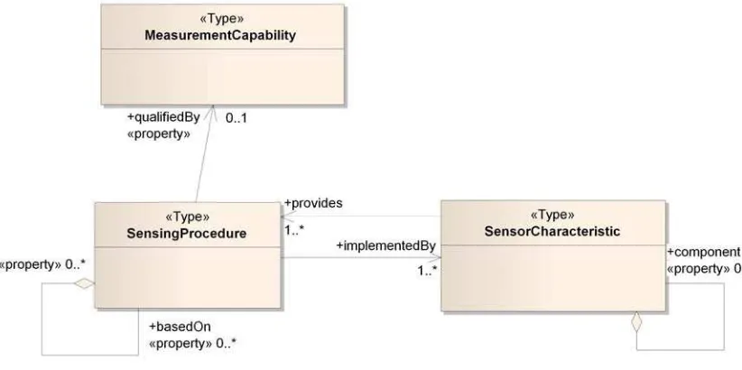
The static module consists of three classes as illustrated in the figure below.
SensorCharacteristic describes the physical part of a sensor, SensingProcedure
describes the procedures implemented by a given physical part, and
MeasurementCapability provides a set of qualifiers for a given SensingProcedure.
Figure 3: Static Module
Every sensor can be described in any arbitrary detail: A sensor can be seen as a black box, and only those aspects relevant for the black box get described, or the black box gets opened like a Russian doll, and all details of each level as well as the dataflow between the various levels get described. To foster this approach, *FL makes use of an enhanced composite pattern, where each level points to elements it is based on or consists of respectively.
Figure 4: Composite pattern of the static module
The right side (grey) describes the physical device with its subcomponents, the left side the implemented procedures (blue). We see that procedures can be based on any number of other procedures. Following the same composite pattern, every
SensorCharacteristic can have any number of subcomponents. It is not necessary that
each SensingProcedure links to a SensorCharacteristic. This is often the case if the
SensingProcedure is a mathematical calculation rather than a physical observation.
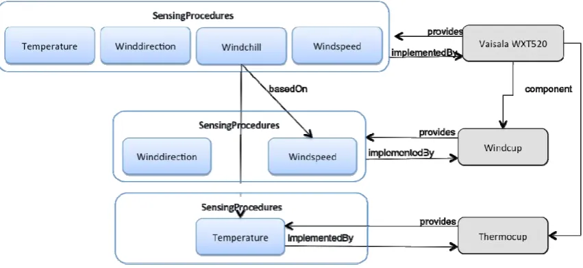
The figure below makes this concept more transparent. It describes the weather station Vaisala 520, which provides a number of observation data at the top level, but consists in fact of a number of subcomponents.
Figure 5: Vaisala 520 weather station
12 Cop
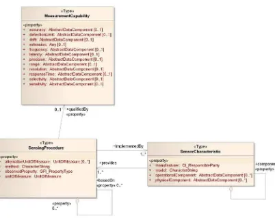
Each SensingProcedure can get further qualified by providing a
MeasurementCapability element, as illustrated in the figure below. The
MeasurementCapability element contains a number of properties typically used to
describe physical sensors. In case that further elements need to be defined,
MeasurementCapability contains an extension element that allows further elements to
be included.
Figure 6: Static module
9.1 SensorCharacteristic
A component of a sensor, which has operational, physical, and thematic
(manufacturer, model) characteristics. It supports one or many SensingProcedure(s).
9.1.1 manufacturer
The manufacturer of the device of type CI_ResponsibleParty from ISO 19115.
9.1.2 model
Simple text string to dsecribe the sensor model.
9.1.3 operationalComponent
Modeled as swe:AbstractDataComponent, the operationalComponent allows to provide information about any operational context information following the SweCommon soft-typing approach.
9.1.4 physicalComponent
Modeled as swe:AbstractDataComponent, the physicalComponent allows to provide information about any physical properties of the sensor.
9.2 SensingProcedure
Description of the observation procedure, i.e. the procedure that produces the estimate of the value of a feature’s property. The element defines the properties of the sensing implemented by a SensorCharacteristic. It is optionally further qualified by a
MeasurementCapability.
9.2.1 alternativeUnitOfMeasure
Allows providing any number of alternative units of measure for a SensingProcedure in case the data is provided in alternative units. The default unit of measure is
provided in the unitOfMeasure property. Uses as ISO 19103 type UnitOfMeasure. It shall be noted that all MeasurementCapabilities given for a SensingProcedure refer to the unit of measure provided in the MeasurementCapability definition. Thus, results provided in any other unit of measure require the transformation of the
MeasurementCapability appropriately.
9.2.2 method
Used method to calculate the results based on physical readings and or calculated values. In reality, almost each electrical sensor uses one sort of calculation to produce the final result, but often this calculation is of minor interest to sensor data users. It is a simple text string and might reference any method description provided by an online resource.
9.2.3 observedProperty
The observedProperty is defined analog to the observedProperty in O&M: The class GFI_PropertyType is an instance of the metaclass GF_PropertyType (ISO 19109), representing feature properties. An instance of GFI_PropertyType shall describe a property that is either assignable or observable, such as "temperature", "height", "color", "material".
9.2.4 unitOfMeasure
The default unit of measure used at the output of this SensingProcedure. It is provided as ISO 19103 type UnitOfMeasure.
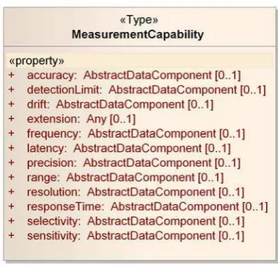
9.3 MeasurementCapability
14 Cop
Figure 7: MeasurementCapability
9.3.1 accuracy
Accuracy can be provided for the entire measurement range of the SensingProcedure, or for specific intervals. It defines the degree of closeness between the observed and the true value of the observed quality.
9.3.2 detectionLimit
The lowest concentration or amount of the target analyte that can be determined to be different from zero by a single measurement at a stated level of probability.
9.3.3 drift
A continuous or incremental change in the reported values of observations over time for an unchanging quality.
9.3.4 extension
The extension mechanism can be used in two ways. Either a domain defines a
separate schema, which might use UncertML for example, or the extension should be of type swe:AbstractDataComponent and follows the standard SweCommon soft-typed approach.
9.3.5 frequency
The measurement frequency: The smallest possible time between one observation and the next.
9.3.6 latency
The time between a request for an observation and the sensor providing a result.
9.3.7 precision
The closeness of agreement between replicate observations on an unchanged or similar quality value: i.e. a measure of a sensor's ability to consistently reproduce an observation.
9.3.8 range
Defines the minimum and maximum property values that can get observed by this device.
9.3.9 resolution
The smallest difference in the value of a quality being observed that would result in perceptibly different values of observation results.
9.3.10 responseTime
The time between a (step) change in the value of an observed quality and a sensor (possibly with specified error) 'settling' on an observed value.
9.3.11 selectivity
Selectivity is a property of a sensor whereby it provides observed values for one or more qualities such that the values of each quality are independent of other qualities in the phenomenon, body, or substance being investigated.
9.3.12 sensitivity
Sensitivity is the quotient of the change in a result of sensor and the corresponding change in a value of a quality being observed.
10 Dynamic Module
The dynamic module provides all information for a sensor in operation, i.e. deployed at a certain location, observing a real world phenomenon, optionally fixed to a platform and so on. The module allows the sensor itself, a collection of sensors, a platform, or a collection of platforms as first order objects.
The dynamic module is linked to the static module via the Sensor class and features a link and override concept: the values defined in the dynamic module override values provided in the static module. This approach minimizes the effort for users to describe their sensors. As long as the sensor is used in its ex-factory settings, the sensor
description just includes links to the XML file provided by the manufacturer. If certain characteristics have been changed, only those characteristics need to get overridden.
16 Cop
The dynamic module consists of three major blocks with optional links.
Figure 8: Major blocks of the dynamic module
The Sensor/Sensing block contains all information to describe the sensor itself and allows overwriting arbitrary aspects of the static module. The Deployment/Platform block contains all information about the deployment of the sensor and its optional fixation to a platform. The third block contains calibration and conformance information.
The following figure page illustrates all details of the dynamic module:
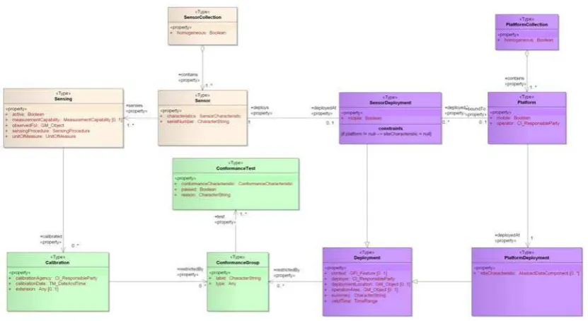
Figure 9: Dynamic Module
10.1 Sensor/Sensing
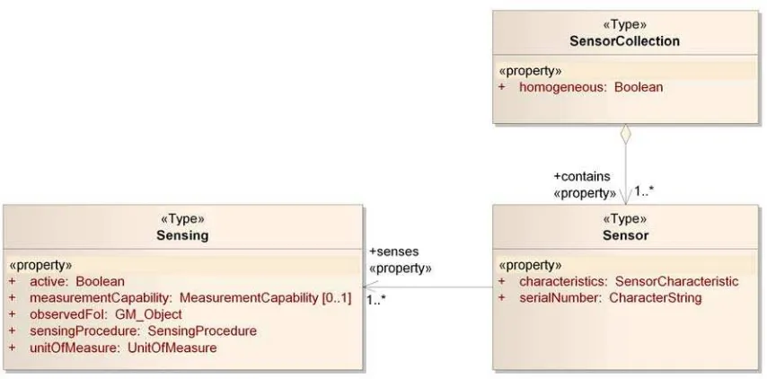
The Sensor/Sensing block contains three classes: Sensor represents the sensor itself and provides the link to the sensor characteristics (see static module). The Sensing class stores information about one of the current sensing processes of the sensor, such as its activity, the observed feature of interest, or specific measurement capabilities, which override the factory defaults.
Figure 10: Sensor related classes of dynamic modules
10.1.1 Sensor
Sensor represents the physical device. In this regard, *FL differs from O&M and SensorML, as *FL differentiates between the device and the processes that are
executed on that device. The device itself is not responsible for creating observations, but its processes.
10.1.1.1 characteristics
Defines the physical components of a sensor, e.g. the different components of a weather station model, as there are thermometer, anemometer etc.
10.1.1.2 serialNumber
Serial number of the sensor (should be globally unique).
10.1.1.3 senses
Senses aggregates the sensing processes(es) of a sensor. *FL differentiates between the physical device and the processes that are executed on that device. The device itself is not responsible for creating observations, but its processes (sensings).
10.1.1.4 deployedAt
A sensor is optionally deployed somewhere. The separation of sensor as such and sensor deployment allows to model the sensor as such (which might not change during a sampling campaign) and its deployments, i.e. "sensor in action" characteristics.
10.1.2 SensorCollection
18 Copyright © 2011 Open Geospatial Consortium
10.1.2.1 homogeneous
Flag to indicate that the collection either contains the history of a single sensor (homogeneous = true), or represents a collection of multiple sensors (homogeneous = false).
10.1.2.2 contains
Aggregation of sensors into the SensorCollection.
10.1.3 Sensing
Sensing is executed on a sensor to create observations for a certain observed property. It refers to a SensingProcedure.
10.1.3.1 active
Flag identifies if the Sensing is currently active or not.
10.1.3.2 measurementCapability
Further defines the measurement capabilities of the sensing object. Overwrites corresponding settings defined in SensorCharacteristic:measurementCapability. property of SensingProcedure. If not given, settings in SensingProcedure remain valid.
10.1.3.3 observedFoI
Defines the real world thing that the sensing can observe. It may be the direct vicinity of a sensor (in-situ sensing), or an remote area (remote sensing). In any case, the Sensing observes a property of the observedFoI.
10.1.3.4 sensingProcedure
SensingProcedure used for this Sensing. Links to StaticModule:SensorCharacteristic:SensingProcedure.
10.1.3.5 unitOfMeasure
Defines the unit of measure currently provided at the Sensing output. The value shall be one of the values provided in the SensorCharacteristic.
10.1.3.6 calibrated
Associates calibration information for the sensing.
10.2 Deployment/Platform
In its current version, SFL does not support further details about the fixation of a sensor at a platform. The current location equals for non-mobile sensor the
deployment location of either the sensor itself or its platform, or in case of mobile sensors, is available as results of a sensing process.
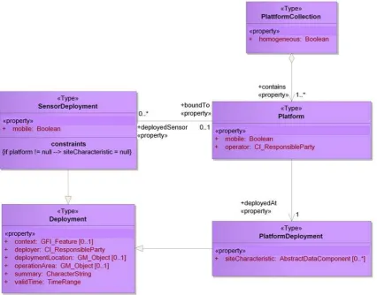
Figure 11: Deployment and platform types
10.2.1 Deployment
Any platform or sensor in action is deployed. Deployment contains all elements common to platform and sensor deployments. If required, a deployment could have several deployment restrictions - as a sensor must be deployed in a certain height, etc.
10.2.1.1 context
Provides information about the context of the deployed sensor, i.e. its "feature of interest" in OGC speach. Serves primarily as an extension point for all domain
specific extensions required to further define the environment a sensor is deployed in.
10.2.1.2 deployer
Party that deployed this item.
10.2.1.3 deploymentLocation
20 Copyright © 2011 Open Geospatial Consortium origin of the platform. If the sensor is deployed without being fixed to a platform, the deploymentLocation defines the absolute location of the sensor. The
deploymentLocation of the PlatformDeployment always defines the absolute location.
10.2.1.4 operationArea
Area where the deployed object is intended to operate. This might be a single point, in case e.g. of a weather station at a fixed location, or e.g. an area in case of a buoy fixed to the seabed or a vessel on a lake, or a e.g. trajectory in case of a drone following a prescribed flight path.
The operation area does not need to be provided if a sensor is connected to a platform, as both operationAreas would be identical.
10.2.1.5 summary
Free text to provide a summary of the deployment.
10.2.1.6 validTime
Time period of this deployment. Might be a closed or open interval.
10.2.1.7 restrictedBy
Any deployment might get restricted according to the definitions given in a conformance group.
10.2.2 SensorDeployment
A sensor deployment binds a sensor for a certain time period to a certain position of a platform.
If the association to Platform is used, the SensorDeployment's deploymentLocation defines the location of the sensor relative to the base of the platform. If the association is not used, the deploymentLocation defines the real world location of the
SensorDeployment.
10.2.2.1 mobile
Indicates if the position of the SensorDeployment is either fixed (i.e. mobile = false) or not fixed (i.e. mobile = true) to a specific location.
10.2.2.2 boundTo
Defines if the deployed sensor is bound/attached to a platform.
10.2.2.3 deploys
10.2.3 PlatformDeployment
The platform deployment defines the concrete deployment of a platform. The core elements are derived from "Deployment". Just additional information is added here.
The base of the Platform is defined as the piece of the platform that is level with its environment. This base acts as the anchor point for the SensorDeployment's
deploymentLocation, which is relative to the base of the Platform.
Examples:
(1) A thermometer attached to a pole is located at 2m above the base of the pole. The base of the pole itself is located at 48N, 7E 217m MSL., i.e. the thermometer is located at 48N, 7E 219m MSL.
(2) A buoy is located at 5N, 22W, and the SensorDeployment at 0 0 -17, then the thermometer is located 17m below the base of the buoy, which is identical with the sea surface.
10.2.3.1 siteCharacteristic
Further characteristics such as the surface area or the climate zone could be provided here.
10.2.4 Platform
The platform is a physical structure that binds one or many sensors.
10.2.4.1 mobile
Defines if the platform is fixed to a single location (mobile = false; e.g. a weather station pole fixed on ground) or mobile.
10.2.4.2 operator
Person or legal person operating the platform.
10.2.4.3 deployedAt
Defines the deployment of a platform.
10.2.4.4 deployedSensor
Links a sensor mounted on the present platform via a SensorDeployment.
10.2.5 PlatformCollection
Aggregation of any number of platforms or history information of a single platform.
10.2.5.1 homogeneous
22 Cop
10.2.5.2 contains
Platform element(s) aggregated in the PlatformCollection.
10.3 Calibration/Conformance
The types support calibration and conformance information about sensors and deployments.
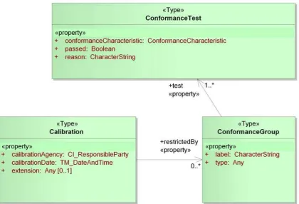
Figure 12: Calibration and conformance types
10.3.1 Calibration
The process of determining the performance parameters of an artifact, instrument, or system by comparing it with measurement standards. Adjustment may be a part of a calibration, but not necessarily. A calibration assures that a device or system will produce results, which meet or exceed some defined criteria with a specified degree of confidence.
10.3.1.1 calibrationAgency
Party responsible for the calibration. Uses ISO 19115 type CI_ResponsibleParty.
10.3.1.2 calibrationDate
Date and time of the last calibration. Uses ISO 19108 type TM_DateAndTime.
10.3.1.3 extension
Extension mechanism to support for domain specific model/schema extensions.
10.3.1.4 restrictedBy
Any calibration might get restricted according to the definitions given in a conformance group.
10.3.2 ConformanceTest
Conformance is defined as a state or acts of adherence to a certain specification, standard, or guideline. The ConformanceTest indicates if a given instance has passed the test for conformance with the specification, standard, or guideline.
10.3.2.1 conformanceCharacteristic
See StaticModule:ConformanceCharacteristic.
10.3.2.2 passed
Flag to indicate if a conformance test has been passed successfully.
10.3.2.3 reason
Description of the aspect that caused the conformance test to fail.
10.3.3 ConformanceGroup
Enables users to group ConformanceTests by category
10.3.3.1 label
A label for the ConformanceGroup to "give it a name".
10.3.3.2 type
A link to further information about this conformance group.
10.3.3.3 test
24 Copyright © 2011 Open Geospatial Consortium
Annex A
XML Examples
1.1 Example: Sensor Characteristic Middleton Pyranometer
The following example defines the sensor characteristic of a low cost first class thermopile pyranometer Middleton SK08, used to observe global solar radiation. The corresponding fact sheet as well as the XML representation given below can be found
online: fact sheet, XML. A SensorDeployment referencing this SensorDescription is
provided in section 1.3.
Listing 5: Sensor characterisitic of a Middleton pyranometer
<?xml version="1.0" encoding="UTF-8"?>
<sfl:SensorCharacteristicxmlns:xlink="http://www.w3.org/1999/xlink"
xmlns:gco="http://www.isotc211.org/2005/gco"xmlns:gmd="http://www.isotc211.org/2005/gmd"
xmlns:gml="http://www.opengis.net/gml/3.2"xmlns:gts="http://www.isotc211.org/2005/gts"
xmlns:gsr="http://www.isotc211.org/2005/gsr"xmlns:gss="http://www.isotc211.org/2005/gss"
xmlns:om="http://www.opengis.net/om/2.0"xmlns:sfl="http://sensorweb.org/sfl"
xmlns:swe="http://www.opengis.net/swe/2.0"xmlns:xsi="http://www.w3.org/2001/XMLSchema-instance"
xsi:schemaLocation="http://sensorweb.org/sfl ../schemas/sfl.xsd"
<swe:QuantityRange definition="http://www.igsi.eu/SensorWeb/terms.html#operatingTemperature">
<swe:uom code="Cel"/>
<swe:value>-35 60</swe:value>
</swe:QuantityRange>
</sfl:operationalComponent>
<sfl:operationalComponent>
<swe:Quantity definition="http://www.igsi.eu/SensorWeb/terms.html#outputImpedance">
<swe:uom code="Ohm"/>
<swe:value>40</swe:value>
</swe:Quantity> </sfl:operationalComponent>
<sfl:physicalComponent>
<swe:Quantity definition="http://www.igsi.eu/SensorWeb/terms.html#outputLead">
<swe:uom code="m"/>
<swe:value>3</swe:value>
</swe:Quantity>
</sfl:physicalComponent>
<sfl:physicalComponent>
<swe:Quantity definition="http://www.igsi.eu/SensorWeb/terms.html#netWeight">
<swe:uom code="kg"/>
<swe:value>0.3</swe:value>
</swe:Quantity>
</sfl:physicalComponent>
<sfl:provides>
<sfl:SensingProcedure gml:id="SP_GlobalSolarRadiation">
<sfl:method>passive thermoelectric sensor, optimised for thermal stability</sfl:method>
<sfl:observedProperty xlink:href="http://www.bom.gov.au/sat/glossary.shtml#globalirradiance"/>
26 Copyright © 2011 Open Geospatial Consortium
<sfl:implementedBy xlink:href="#Middleton_Pyranometer_SK08"/>
</sfl:SensingProcedure>
</sfl:provides>
</sfl:SensorCharacteristic>
1.2 Example: Sensor Characteristic Vaisala WXT 520 Weather Station
The following example defines the sensor characteristic of a Vaisala WXT520 weather station. The corresponding fact sheet as well as the XML representation
given below can be found online: fact sheet, XML.
Listing 6: SensorCharacteristic of a Vaisala WXT 520 Weather Station
<?xml version="1.0" encoding="UTF-8"?>
<sfl:SensorCharacteristicxmlns:xlink="http://www.w3.org/1999/xlink"
xmlns:gco="http://www.isotc211.org/2005/gco"xmlns:gmd="http://www.isotc211.org/2005/gmd"
xmlns:gml="http://www.opengis.net/gml/3.2"xmlns:gts="http://www.isotc211.org/2005/gts"
xmlns:gsr="http://www.isotc211.org/2005/gsr"xmlns:gss="http://www.isotc211.org/2005/gss"
xmlns:om="http://www.opengis.net/om/2.0"xmlns:sfl="http://sensorweb.org/sfl"
xmlns:swe="http://www.opengis.net/swe/2.0"xmlns:xsi="http://www.w3.org/2001/XMLSchema-instance"
xsi:schemaLocation="http://sensorweb.org/sfl ../schemas/sfl.xsd"
xlink:href="http://www.vaisala.com/en/support/servicecenters/Pages/default.aspx"/>
<gmd:role/>
</gmd:CI_ResponsibleParty>
</sfl:manufacturer>
<sfl:model>Vaisala Weather Transmitter WXT5290</sfl:model>
<sfl:operationalComponent>
<swe:QuantityRange definition="http://www.igsi.eu/SensorWeb/terms.html#operatingTemperature">
<swe:uom code="Cel"/>
<swe:value>-52.0 60.0</swe:value>
</swe:QuantityRange> </sfl:operationalComponent>
<sfl:operationalComponent>
<swe:QuantityRange definition="http://www.igsi.eu/SensorWeb/terms.html#storageTemperature">
<swe:uom code="Cel"/>
<swe:value>-60.0 70.0</swe:value>
</swe:QuantityRange> </sfl:operationalComponent>
<sfl:operationalComponent>
<swe:QuantityRange definition="http://www.igsi.eu/SensorWeb/terms.html#operatingVoltage">
<swe:value>5.0 32.0</swe:value>
</swe:QuantityRange> </sfl:operationalComponent>
<sfl:operationalComponent>
<sfl:ConditionalValue definition="http://www.igsi.eu/SensorWeb/terms.html#typcialPowerConsumption">
<sfl:condition>
<swe:QuantityRange definition="http://www.igsi.eu/SensorWeb/terms.html#heatingVoltage">
<swe:uom code="V"/>
<swe:value>5.0 32.0</swe:value>
</swe:QuantityRange> </sfl:operationalComponent>
<sfl:physicalComponent>
<swe:Quantity definition="http://www.igsi.eu/SensorWeb/terms.html#netWeight">
<swe:uom code="g"/>
<swe:value>650.0</swe:value>
</swe:Quantity>
</sfl:physicalComponent>
<sfl:physicalComponent>
<swe:Category definition="http://www.igsi.eu/SensorWeb/terms.html#housing">
<swe:value>IP65</swe:value>
</swe:Category>
</sfl:physicalComponent>
<sfl:provides>
<sfl:SensingProcedure gml:id="windSpeed">
<sfl:method>Vaisala WINDCAP®sensor uses ultrasound to determine horizontal wind speed and
direction.</sfl:method>
<sfl:observedProperty xlink:href="http://www.igsi.eu/SensorWeb/terms.html#windSpeed"/>
28 Copyright © 2011 Open Geospatial Consortium
<sfl:implementedBy xlink:href="#SensorCharacteristic_Vasiala_WXT520"/>
</sfl:SensingProcedure>
</sfl:provides>
<sfl:provides>
<sfl:SensingProcedure gml:id="windDirection">
<sfl:method>Vaisala WINDCAP®sensor uses ultrasound to determine horizontal wind speed and
direction.</sfl:method>
<sfl:observedProperty xlink:href="http://www.igsi.eu/SensorWeb/terms.html#windDirection"/>
<sfl:unitOfMeasure uom="deg"/>
<sfl:qualifiedBy>
<sfl:accuracy>
<sfl:implementedBy xlink:href="#SensorCharacteristic_Vasiala_WXT520"/>
</sfl:SensingProcedure>
<sfl:observedProperty xlink:href="http://www.igsi.eu/SensorWeb/terms.html#rainfall"/>
<sfl:unitOfMeasure uom="mm"/>
<sfl:implementedBy xlink:href="#SensorCharacteristic_Vasiala_WXT520"/>
</sfl:SensingProcedure>
</sfl:provides>
<sfl:provides>
<sfl:SensingProcedure gml:id="rainfall_duration">
<sfl:method>
30 Copyright © 2011 Open Geospatial Consortium directly to the accumulated rainfall.
</sfl:method>
<sfl:observedProperty xlink:href="http://www.igsi.eu/SensorWeb/terms.html#rainfallDuration"/>
<sfl:unitOfMeasure uom="s"/>
<sfl:implementedBy xlink:href="#SensorCharacteristic_Vasiala_WXT520"/>
</sfl:SensingProcedure>
</sfl:provides>
<sfl:provides>
<sfl:SensingProcedure gml:id="rainIntensity">
<sfl:method>
<sfl:observedProperty xlink:href="http://www.igsi.eu/SensorWeb/terms.html#rainfallIntensity"/>
<sfl:unitOfMeasure uom="mm/h"/>
<sfl:implementedBy xlink:href="#SensorCharacteristic_Vasiala_WXT520"/>
</sfl:SensingProcedure>
</sfl:provides>
<sfl:provides>
<sfl:SensingProcedure gml:id="hail">
<sfl:method>cumulative amount of hits against the collecting surface</sfl:method>
<sfl:observedProperty xlink:href="http://www.igsi.eu/SensorWeb/terms.html#hail"/>
<sfl:unitOfMeasure uom="http://www.igsi.eu/SensorWeb/terms.html#hitsPercm2"/>
<sfl:alternativeUnitOfMeasure uom="http://www.igsi.eu/SensorWeb/terms.html#hitsPerinches2"/>
<sfl:alternativeUnitOfMeasure uom="http://www.igsi.eu/SensorWeb/terms.html#numberOfHits"/>
<swe:uom xlink:href="http://www.igsi.eu/SensorWeb/terms.html#hitsPerinches2"/>
<sfl:implementedBy xlink:href="#SensorCharacteristic_Vasiala_WXT520"/>
</sfl:SensingProcedure>
</sfl:provides>
<sfl:provides>
<sfl:SensingProcedure gml:id="hail_duration">
<sfl:method>The WXT520 precipitation measurement is based on the unique
<sfl:observedProperty xlink:href="http://www.igsi.eu/SensorWeb/terms.html#hailDuration"/>
<sfl:unitOfMeasure uom="s"/>
<sfl:implementedBy xlink:href="#SensorCharacteristic_Vasiala_WXT520"/>
</sfl:SensingProcedure>
</sfl:provides>
<sfl:provides>
<sfl:SensingProcedure gml:id="hailIntensity">
<sfl:method>
<sfl:observedProperty xlink:href="http://www.igsi.eu/SensorWeb/terms.html#hailIntensity"/>
32 Copyright © 2011 Open Geospatial Consortium </sfl:qualifiedBy>
<sfl:implementedBy xlink:href="#SensorCharacteristic_Vasiala_WXT520"/>
</sfl:SensingProcedure>
</sfl:provides>
<sfl:provides>
<sfl:SensingProcedure gml:id="air_temperature">
<sfl:method>
Barometric pressure, temperature, and humidity measurements are
combined in the PTU module using capacitive measurement for each parameter. </sfl:method>
<sfl:observedProperty xlink:href="http://www.igsi.eu/SensorWeb/terms.html#airTemperature"/>
<sfl:unitOfMeasure uom="deg"/>
<sfl:implementedBy xlink:href="#SensorCharacteristic_Vasiala_WXT520"/>
</sfl:provides>
<sfl:provides>
<sfl:SensingProcedure gml:id="barometric_pressure">
<sfl:method>
Barometric pressure, temperature, and humidity measurements are
combined in the PTU module using capacitive measurement for each parameter. </sfl:method>
<sfl:observedProperty xlink:href="http://www.igsi.eu/SensorWeb/terms.html#barometricPressure"/>
<sfl:unitOfMeasure uom="hPa"/>
<!-- The measurement capabilities have been removed. -->
<sfl:implementedBy xlink:href="#SensorCharacteristic_Vasiala_WXT520"/>
</sfl:SensingProcedure> </sfl:provides>
<sfl:provides>
<sfl:SensingProcedure gml:id="relative_humidity">
<sfl:method>
Barometric pressure, temperature, and humidity measurements are
combined in the PTU module using capacitive measurement for each parameter. </sfl:method>
<sfl:observedProperty xlink:href="http://www.igsi.eu/SensorWeb/terms.html#relativeHumidity"/>
<sfl:unitOfMeasure uom="%"/>
<!-- The measurement capabilities have been removed. -->
<sfl:implementedBy xlink:href="#SensorCharacteristic_Vasiala_WXT520"/>
</sfl:SensingProcedure>
</sfl:provides>
</sfl:SensorCharacteristic>
1.3 Example: Sensor Deployment Middleton Pyranometer
The example given below describes a Middleton pyranometer being deployed. It references the SensorCharacteristic provided in clause 1.1. This is the intended usage, as the pyranometer is used with the ex-factory settings. Thus, the sensor
characteristics provided by the manufacturer don’t need to get replicated or
overwritten, but simply referenced. The XML representation can be found online as
well.
Listing 7: Example of a SensorDeployment for Middleton Pyranometer SK08
<?xml version="1.0" encoding="UTF-8"?>
This files describes the deployment of the MIddleton pyranometer on the sampling site. The pyranometer is deployed on ground at a
34 Copyright © 2011 Open Geospatial Consortium
<gmd:voice>
<gco:CharacterString>+49.6171.2088551</gco:CharacterString> </gmd:voice>
</gmd:CI_Telephone> </gmd:phone>
</gmd:CI_Contact> </gmd:contactInfo> <gmd:role/>
</gmd:CI_ResponsibleParty> </sfl:deployer>
<sfl:deploymentLocation>
<gml:Point gml:id="p1" srsDimension="2" srsName="urn:ogc:def:crs:EPSG:6.6:4326"> <gml:pos>50.199927 8.581095</gml:pos>
</gml:Point> </sfl:deploymentLocation> <sfl:mobile>
false
</sfl:mobile> <sfl:deploys>
<sfl:Sensor gml:id="pyranometer01">
<sfl:serialNumber>2735 2357 23574 96</sfl:serialNumber>
<sfl:characteristics xlink:href="http://www.igsi.eu/SensorWeb/SC_MiddletonPyranometer.xml"/> <sfl:senses>
<sfl:Sensing gml:id="pSensing01"> <sfl:sensingProcedure
xlink:href="http://www.igsi.eu/SensorWeb/SC_MiddletonPyranometer.xml#SP_GlobalSolarRadiation"></sfl:sensingPr ocedure>
<sfl:unitOfMeasure uom="microVolt"/> <sfl:active>true</sfl:active>
<sfl:observedFoI/> </sfl:Sensing>