EVALUATING PARAMETERS AFFECTING THE GEOREFERENCING ACCURACY OF
TERRESTRIAL LASER SCANNERS
M. Miria, M. Varshosazb
a, b
Dept. of Photogrammetry and Remote Sensing, Faculty of Geodesy and Geomatics Eng.,
K.N. Toosi University of Technology, Tehran, Iran
a
mohsen.miri@yahoo.com
bvarshosazm@kntu.ac
.irKEY WORDS:
Terrestrial Laser Scanners, Accuracy, Affecting Parameters
ABSTRACT:
Today laser scanning is used as a powerful technology in measuring various simple and complex objects in cultural heritage applications. Depending on the size and the complexity of the objects, these measurements are usually made from several stations. Similar to all other surveying techniques, the coordinate systems of such measurements need to be registered. For this, a number of retro-reflective targets visible from different stations are used. In practice, the target centres are entered in the computations. The accuracy of the target centres, therefore, need to be high or the final object coordinates might not be of sufficient accuracy. A number of factors including the distance between a target and the laser scanner, the direction of the target surface with respect to the laser scanner beams, the intensity and the number of reflected laser beams affect the accuracy of target centres. In this paper, various tests are carried out to examine the effect of such factors on the accuracy of coordinates obtained for the target centres. The results show that the distance to the laser scanner and the angle between a target surface and the corresponding laser beams have considerable effects on the locational accuracy of the targets.
1. INTRODUCTION
Recent years have seen the use of laser scanners as powerful new surveying tools in measurement of 3D objects. Typically, laser scanners are divided into airborne and terrestrial categories. The former, so called LIDAR, is mainly used in topographic applications to create Digital Elevation Models (DEM). In contrast, the latter, which is the main concern of this paper, has numerous applications in various fields like civil applications, reverse engineering, and cultural heritage documentations. Similar to all other surveying instruments, to measure objects or sites, the measurements need to be made from several stations to cover the area of interest. In this regard, the measurements made in multi-stations need to be registered. For this, a number of retro-reflective targets are placed in the area or around the object to be measured. The coordinates of these targets are then used to link the coordinate system of the stations. As a result, the positional accuracy of these targets is of great importance, or the final measurements may not be of sufficient reliability. In this paper, the elements affecting the accuracy of these targets are studied. In the following, the laser scanning technology and its principles are briefly reviewed. Then, parameters affecting the accuracy of registering targets are evaluated. Various tests carried out to study the role of these parameters on the registration accuracy are reported and conclusions are, finally, made.
2. BASICS OF POSITIONING BY TERRESTRIAL LASER SCANNERS
Laser scanning is a contactless method which works by reflectorless distance measurement [1]. The coordinates of points are calculated by measuring the beam’s travel time from the scanner to the object points. Similar to modern tachymeters, the distance measurement is done reflectorless and in a regular grid. The difference is that, laser scanners send thousands of beams and continously measure the reflecdted ones. The output
is a huge number of points, so called point cloud, with known coordiantes withwithin the scanenner’s coordiatne system. The whole area around the scanner is usually measured in a relatively short time, normally within minutes.
As mentioned above, to map a large area, a number of stations are to be used which have to be registered through the use of retro-reflective targets. The intensity of beams hitting such targets is larger than that of normal object points, making them distinguishable by the scanner very easily. As a result, the centre of the targets is used to register the coordinate system of the scanner at different positions. The targets are made in different shapes like circles, cylinders etc. A number of parameters affect the accuracy of targets including the distance between a target and the laser scanner, the direction of the target surface with respect to the laser scanner beams, the intensity Geomatics Eng. Faculty, K.N. Toosi University of Technology, Iran. Many retro-reflective circular flat targets with diameter of 5cm (Figure 1) were attached to the walls surrounding the playground. Figure 2 shows a panoramic snapshot of the test area. The targets were attached in two levels. To simplify the discussions, the names of the targets on the northern upper and lower levels start with U and L respectively, while those on the western wall start with T and D (Top and Down). The targets were observed by a Trimble 5600 total station having nominal angle and distance precisions of 3” and 3mm respectively. The area was then scanned with a Riegl LMS 360i scanner with 6mm accuracy from four locations, three of which were used in the discussion as shown in Figure 3.
International Archives of the Photogrammetry, Remote Sensing and Spatial Information Sciences, Volume XXXVIII-5/W16, 2011 ISPRS Trento 2011 Workshop, 2-4 March 2011, Trento, Italy
Figure 1. 5cm flat retro-reflector
Figure 2: The test area with the location of the targets used
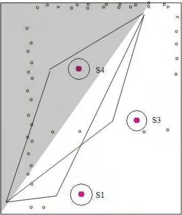
Figure 3: Scanner locations and the planimetric location of the targets
4. VALUATING THE EFFECT OF DIFFERENT PARAMETERS ON THE ACCURACY OF
GEOREFERENCING TLS DATA
In this section, the effects of the mentioned parameters on the accuracy are studied. For this three types of figures are used:
Geometric figure: this shows the difference between the coordinates of the targets measured by scanner and the total station
Intensity figure: this shows the amount of reflected intensity from the targets which is measured by the scanner. The intensity value ranges between 0 and 1
Density figure: this figure is an indication on the number of reflected points that are received and measured by the scanner
Range figure: this shows the distance from the target to the scanner.
In the following, the effect of range (distance between a target and the scanner’s position at each station), inclination (angle between scanner’s beams and the target’s surface normal) and the number of reflected points (scanned pixels) on the accuracy of geo-referencing the scanner is studied. To do so, the data from stations 1, 3 and 4 were evaluated. The results were almost the same for the data at any single station.
Range: Figure 4 shows the results from station 1. In this station, targets D9 to D12 were used as control points. As can be seen, the accuracy of points on the northern wall (starting with U and L) have a low accuracy of 2.5-5cm, especially in x direction. The figure also shows a convergence between x and y error lines moving from L9 to L1. Looking at Figure 3, one can realise that the distance between the scanner and the targets on the northern wall reduces from L9 to L1. This suggests that accuracy of a target increases as its the distance to the scanner is reduced. International Archives of the Photogrammetry, Remote Sensing and Spatial Information Sciences, Volume XXXVIII-5/W16, 2011
ISPRS Trento 2011 Workshop, 2-4 March 2011, Trento, Italy
The accuracy of the points T11, T12 and D8 also confirms this. In addition, the deviation points in z direction remains almost constant which could be due to small vertical angular changes between beams to U and L points. This difference, however, is a little bigger for T points as the distance from the scanner to the points is smaller and hence the effect of the vertical angle is more distinguishable.
Number of scanned pixels: for this test, the overall error of points at station 1 was used. Figure 5, shows the overall accuracy of targets at Station 1. As can be seen in except L5, all other points starting with L and U are among outliers. Having a simultaneous look at the range (distance to the scanner), the number of reflected pixels from a target, and the accuracy of the targets reveals the fact that the number of pixels has an inverse relation with the target’s range which, in turn, leads to a reduction in its coordinate accuracy.
Figure 4: Accuracy (top), intensity (middle), and density (down) of the target points at Station 1
Figure 5: Accuracy and its relation with the number of pixels at Station 1
Figure 6: Accuracy and its relation at Station 3
International Archives of the Photogrammetry, Remote Sensing and Spatial Information Sciences, Volume XXXVIII-5/W16, 2011 ISPRS Trento 2011 Workshop, 2-4 March 2011, Trento, Italy
Orientation angle: in this section the data from Station 3 is used. In addition to the distance there exist another important parameter which affects the accuracy of points. This parameter is the angle between a scanner’s beam with respect to the normal to the targets surface. In other words, as can be seen in Figure 3, despite the increase in the number of pixels scanned from L9 to L1 where the range decreases, the overall accuracy of the points has reduced. Looking at Figure 1, one can realise this has a direct relation to the mentioned angle.
5. CONCLUSIONS
In this paper, the accuracy of registration of a network of terrestrial laser scanners and its relation to the range, beams inclination (with respect to a target’s surface) and the number of scanned points on the targets was studied. It was shown that increasing the range or the inclination angle leads to a decrease in the accuracy of the target coordination. It was noted that the overall accuracy is a trade-off between these factors. Thus not only the distance to a targets but also its inclination angle must be taken into account.
6. REFERENCES
[1]:J. Jansa, N. Studnicka, G. Forkert, A. Haring, H. Kager,. “Terrestrial laser scanning and photogrammetry – Acquisitions techniques complementing one another”, ISPRS 2004. Istanbul. Proceeding CD. Commission V, 2004.
International Archives of the Photogrammetry, Remote Sensing and Spatial Information Sciences, Volume XXXVIII-5/W16, 2011 ISPRS Trento 2011 Workshop, 2-4 March 2011, Trento, Italy