LINEAMENT EXTRACTION FROM SPOT 5 AND NIGERIASAT-X IMAGERY OF THE
UPPER BENUE TROUGH, NIGERIA
*Ogunmola J.K , Ayolabi E.A, and Olobaniyi S.B
Department of Geosciences, University of Lagos, Nigeria, email: [email protected]
KEY WORDS: Geology, SPOT, Nigeriasat-X, DEM, Processing
ABSTRACT:
The Upper Benue Trough is part of the Benue Trough of Nigeria and is comprised of three basins: the east–west trending Yola Basin (Yola Arm), the north– south trending Gongola Basin (Gongola Arm) and the northeast– southwest trending Lau Basin (Main Arm). This research is an ongoing research at understanding the structural framework of the Upper Benue Trough using several techniques including the use of Remote Sensing and GIS. Several digital image enhancement techniques such as general contrast stretching and edge enhancement were applied to the NigeriaSat-X and SPOT 5 image in ERDAS IMAGINE 9.2 after which structures were mapped out on-screen using ArcMap 10. The Digital Elevation Model (DEM) of the Trough was also used to enhance geomorphic features. The analysis carried out on the images revealed that lineaments are abundant in the Upper Benue Trough and they can be subdivided into four major trends, NE-SW, NW-SE, W-E and N-S in order of abundance and range in length from about 300m to 26km. Several faults were also mapped out within the Basin such as a sinistral fault around Bakoreji village in Bauchi, a dextral fault close to Kalmai town in Gombe and a dextral fault close to Wong in Taraba. It was discovered that some of the sites where minerals such as lead and zinc ores are being mined occur in the zones of high lineament density. This study shows the capability of the DEM, SPOT 5 and NigeriaSat-X images for lineament/structural interpretations.
1.0 INTRODUCTION
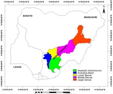
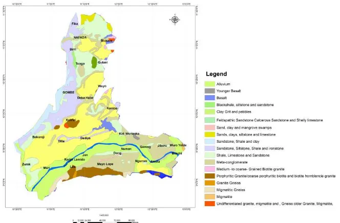
The Upper Benue Trough (Fig 1) is part of the Benue Trough of Nigeria and is comprised of three basins: the east–west trending Yola Basin (Yola Arm), the north– south trending Gongola Basin (Gongola Arm) and the northeast– southwest trending Lau Basin (Main Arm). The geological map of the Upper Benue is shown in Fig 2. Stratigraphic relationships in the Upper Benue Trough are depicted in Fig. 3. The earliest Cretaceous sequence is the continental Bima sandstone, which rests unconformably on the undulating PreCambrian Basement. The unit is a thick and widespread series of continental grits, sandstones and clays. In the north, these beds are wholly continental, but in the south, marine shales occur in the
Figure 1. Map of Nigeria showing the major divisions of the
Benue Trough . (after Ologun et al 2008)
lower part of the formation (Carter et al., 1963). Overlying the Bima Formation is the paralic Yolde Formation (Early Turonian), comprising alternating sandstones and shales. The sandstones are fine- to medium-grained and light-brown, with shale and limestone intercalations. Thick marine Turonian shales with limestones at their base overlie the transitional deltaic-to-marine Yolde Formation in many localities. These shales, called the Pindiga Formation in the Upper Benue Trough, are found in the south to be laterally equivalent to the Jessu Formation, consisting of interbeds of shales, sandstones and limestones, the gypsiferous Numanha Formation and the Sukuliye Formation (shales and limestones). The type localities of the Sukuliye and Numanha Formations occur at Sukuliye and Lamja Kasa, respectively (Carter et al., 1963). These two units succeed the Jessu Formation.
for many years, from the early years of the last century (Hobbs, 1904, 1912) up to now. From the beginning, geologists realized that linear features are the result of zones of weakness or structural displacement in the crust of the earth. A lineament is a linear or curvilinear mappable feature of a surface whose parts align in a straight or slightly curving relationship. They may be an expression of a fault or other line of weakness. The surface features making up a lineament may be geomorphological, i.e. caused by relief or tonal, i.e. caused by contrast differences. Straight stream/river valleys and aligned segments of a valley are typical geomorphological expressions of lineaments. A tonal lineament may be a straight boundary between areas of contrasting tone. Differences in vegetation, moisture content, and soil or rock composition account for most tonal contrast (O’Leary et al. 1976). In general, linear features are formed by edges, which are marked by subtle brightness differences in the image and may be difficult to recognize. On the earth, lineaments could be (1) straight stream/river and valley, (2) aligned surface depressions, (3) tonal changes in soil (4) alignments in vegetation, (5) vegetation type and height changes, or (6) abrupt topographic changes. All of these phenomena might be the result of structural phenomena such as faults, joint sets, folds, cracks or fractures. The old age of many geological lineaments means that younger sediments commonly cover them. When reactivation of these structures occurs, this results in arrays of brittle structures exposed on the surface topography. Similarly, the surface expression of a deep-seated lineament may be manifested as a broad zone of discrete lineaments (Richards, 2000). In order to map structurally significant lineaments, it is necessary to, by careful and critical analysis of the image, to differentiate between geological and man-made structures. Geological structures and rock boundaries that show correlation with relief can be mapped with detailed topographic analysis using Digital Elevation Models (DEM) because they depict accurate representation of relief. Terrain analysis using digital elevation models is being increasingly used in geological and hydrological research (Badura and Przybylski 2005, Wilson and Gallant, 2000). Linear features that are not visible on conventional maps become distinct features. Three-dimensional visualization of the surface of the Earth and its examination at different angles and at different orientation of illumination is useful in geological and geomorphological studies. For this study 30 m resolution DEM of the Upper Benue Trough was used. One of the usefulness of DEM lies in the fact that there are no vegetation and most manmade constructions within it which makes it possible to delineate geological structures, rock boundaries and drainage patterns of highly vegetated and built-up areas.
1.1 Geological Setting: The Benue Trough is a tectonic feature that is part of the West African rift system. The Trough consist of a long stretch of sedimentary basin running from about the northern tip of the Niger delta basin and terminates under the Chad basin and sandwiched by the Basement complex areas in the north and south of River Benue filled with sediments that are Middle-Late Albian in age (Offodile, 1976). The sediments have been found to vary in thickness between 5.5-7.0 km (Carter et al., 1963). The Trough has a NE-SW strike and its narrowest part is about 130km and the broadest part about 200km due to the existence of two parallel rifts (Ajayi and Ajakaiye,1981). The Trough has been tectonically active from the Albian which has left the sediments to be highly folded in areas such as the Abakaliki area where the site of maximum sediment deposition was pushed westward and north-eastwards towards the Anambra basin which began to subside
and parts of the Upper Benue especially at the contact between the sediments and the basement rocks, example can be seen near Gboko. Common features in the trough are horst blocks and grabens or half grabens that have been filled with sediments that vary in thickness and also show some amount of faulting that resulted from syn-depositional deformation (Benkhelil, 1989). Based on their different structures and stratigraphic framework, Benkhelil (1989) partitioned the trough into three parts, namely the Lower (Southeast) Benue which is about 150 km wide includes the Abakaliki Anticline composed of folded Cretaceous sediments and the Anambra Basin which trends in a N30 ° E direction and is composed of Cretaceous sediments; the Middle Benue composed of Albian sediments that have been folded in the Keana area to form the Keana Anticline is the elongate part of the trough and lastly the Upper (northeast) Benue which consists of basement rocks and sediments such as the Keri-Keri formation. A prominent feature in the Upper Benue is the Kaltungo inlier.
Within the Benue Trough, there are so many evidences of extensional movements, from large faults in the Late Jurasic-Early Cretaceous Sandstones (Guiraud, 1993) to small-scale fractures of the Lower Benue Trough (Benkhelil, 1988). The area is characterised by several fault zones striking N 30° E to N 60° E cross-cutting the sedimentary and basement rocks (Guirard et al, 1989). The Mesozoic deposits have also been deformed by asymmetric large scale folds (Lamurde and Jarawa anticlines, Dadiya syncline) that trend NE-SW to N 80° E . It is believed that most of the sedimentary structures within the Trough developed as a result of Basement-seated transcurrent faults (Benkhelil et al,1998). Ananaba and Ajakaiye (1987) observed from Landsat imagery that the trend of the lineaments are predominantly north-east-southwest, northwest-southeast and north-south.
2.0 MATERIALS AND METHODS
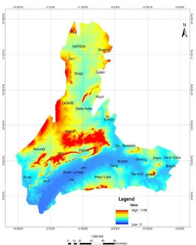
The satellite images used for this study include SPOT 5 image with a high resolution (5m) and the NigeriaSat-X image (Fig 5) with 22m resolution. The Digital Elevation Model (fig 6) is from the SRTM (Shuttle Radar Terrain Mission) of NASA.
2.1 Image Processing
Several digital image enhancement techniques such as general contrast stretching and edge enhancement were applied to the SPOT 5 and NigeriaSat-X images in ERDAS IMAGINE 9.2.
2.2 Topographic Analysis
Several topographic analyses were carried out on the DEM and include-
2.2.1 Fill: Digital Elevation Models (DEMs) may sometimes have imperfections such as sinks and peaks. A sink is a cell with an undefined drainage direction, no cells surrounding it are lower. A peak is a cell where no neighbouring cells are higher. The fill tool in the Spatial Analyst of ArcMap was used to fill the sinks and remove the peaks within the data.
of the upper Benue Trough using the Digital Elevation Model (DEM).
Figure. 3. Stratigraphic correlation of Upper cretaceous strata in Upper Benue trough (Idowu and Ekwezor, 1989).
Figure 2. Geological map of the Upper Benue Trough (modified from NGSA MAP, 2004)
Figure 5. NigeriaSat-X image of the Upper Benue Trough
2.2.7 Shaded Relief/Hill Shading: This image shows relief by simulating the effect of the sun’s illumination on the terrain.
2.2.8 Stream Network: This is a process in the Spatial Analyst of ArcMap which performs a conditional if/else evaluation on each of the cells of a raster. Since the flow accumulation shows the number of cells that drain to a particular cell, it can be used to define a stream. It is assumed that a stream is formed when a certain area (threshold) drains to a point. For this work, we used an optimum threshold of 100 cells. The flow direction grid and flow accumulation grid was used to generate the stream of 0 indicates the surface is flat.
2.2.4 Slope Analysis: Information of slope can be used to assess how geology affects topography. A slope’s steepness could be correlated to the resistance of the rocks exposed. The slope map of the trough was generated using the spatial Analyst (slope) of ArcMap. The tool identifies the slope (gradient, or rate of maximum change in Z-value) from each cell of a raster surface. The range of slope varies from 0 – 90 degrees.
2.2.5 Flow Direction: This method derives a raster of several flow directions from each cell to its steepest downslope neighbor. If the value of a cell is lower than those of eight of its surrounding neighbors, the flow direction will be towards this cell. The map of flow direction was derived using the Spatial Analyst tool of ArcMap.
2.2.6 Flow Accumulation: This process generates a raster of accumulated flow from surrounding cells into a cell. Cells that have no flow direction will only receive flow but will not based on their number of tributaries. Two methods are usually used. The Stahler method assigns an order of 1 to all links without tributaries (Stahler, 1957). The stream order increases when streams of the same other intersect, that is the intersection of two first-order links will create a second-order link, the intersection of two second order links will create a third order link, and so on. The other method is the Shreve method which accounts for all links in the network (Shreve, 1957). The intersection of two first-order links, creates a second order link, the intersection of a first-order and second-order link creates a third-order link, and the intersection of a second-order and third-order link creates a fifth-order link. The strahler method was used to generate the stream network of the upper-Benue.
2.2.10 Stream to Feature: This method uses the stream order function in ArcMap Spatial Analyst to convert the stream raster to a polyline feature class. In other words, it converts a raster depicting a linear network to features representing the linear network.
2.4 Structural Mapping: The ArcMap is a powerful GIS tool that can be used to integrate different data sets that have the same spatial reference to extract information that may be common or different among the various data sets. All the various data sets including the Spot 5 and NigeriaSat-X images, the curvature, drainage, and the shaded relief maps were displayed in ArcMap and mapping was done by studying one layer at a time and comparing with other layers in the GIS environment. The geological map was useful because it showed the distribution of rock types on the surface. One of the advantages of working in a GIS environment using several data sets is the opportunity to examine features that are spatially referenced. A feature that is less pronounced in one data set can be more pronounced in another data set and this can be better studied in a GIS environment. To start digitizing the lineaments, a shapefile was created in ArcCatalog and it was set to the same coordinate and spatial reference as the other data sets. The digitizing tool was then used to map out the Figure 6. Digital Elevation Model (DEM) of the
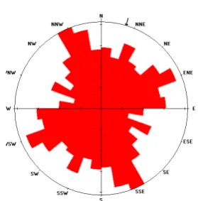
lineaments observed from the various data sets on-screen. A rose diagram of the lineaments within the trough was created in Georient software.
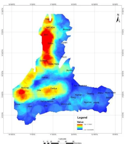
2.5 Lineament Density: Karcz (1978) defined lineament density as the summed length of lineaments within a specified unit area of a grid. The lineament density map of the area was computed in ArcMap using the line density of the Spatial Analyst tool which calculates a magnitude per unit area from polyline features that fall within a radius around each cell.Only the portion of a line within the neighborhood is considered when calculating the density. If no lines fall within the neighborhood at a particular cell, that cell is assigned NoData.
3. 0 RESULTS
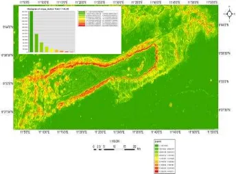
3.1 Topographic profiles: The profiles taken across several structures revealed that the highest peaks in the area are about 1200m as can be seen in the area around Dadiya syncline (fig 7 ).
3.2 Slope: The distribution of slope in the Upper Benue Trough are similar, for example, around the Dadiya syncline, the distribution is non-symetric and skewed right and the values range from 0-58 degrees (fig 8). Green represents shallow slopes and red are steep slopes. The range of slope with the highest frequency is between 0-8 degrees signifying that the area is a relatively flat terrain with ridges of the Dadiya syncline showing slope values of 21- 59 degrees.
It was observed that around the Dadiya syncline, the area of steepest slopes coincides with the boundaries between the more resistive sandstone, siltstone, shale, ironstone and the less resistive feldspathic, calcareous sandstone.
3.3 Shaded Relief/Hill Shading: The output hillshade map of the Upper Benue Trough viewed from different illumination directions highlighted several structures that were not clearly visible on the Spot 5 and NigeriaSat-X images. Example is seen in the area around the Dadiya Syncline (fig9).
Figure 9. Shaded Relief map of the area around Dadiya Syncline
3.4 Curvature: From the output of the curvature map (fig 10), it was observed that areas with large curvature values correlates with areas where rocks outcropped on the surface which was useful in mapping areas with thick vegetation on the satellite images. Areas with low curvature values correlates with stream channels.
Figure 10. Curvature map of parts of the area around Dadiya Syncline
3.5 Stream Network/stream order/stream to feature: The stream network of the Upper Benue Trough generated from the stream direction grid and stream accumulation grid were the same as observed on the satellite images. The stream order generated based on the Strahler method generated produced the drainage map of the study area (fig 11) which is useful in mapping out lineaments since straight stream channels are most likely to be along fracture zones.
3.6 3D visualisation: The 3D view of the DEM (Fig 12) displayed patterns that were not visible in 2D.
Figure 7. Topographic profile taken around the Dadiya Syncline
3.7 Structural mapping: The lineaments extracted from the images (SPOT 5, NigeriaSat-X) and the several outputs of the DEM range in length from 300m to 26 km (Fig 13). The rose diagram suggests predominantly northwest-southeast, northsouthwest and north-south as well as very few east-west trends (fig 15).Several faults were also mapped out within the Basin such as a sinistral fault around Bakoreji village in Bauchi, a dextral fault close to Kalmai town in Gombe and a dextral fault close to Wong in Taraba.
3.8 Lineament Density: The lineament density map of the Upper Benue Trough is shown in fig 15. The map shows three major zones of high density of lineaments and they all fall within the Gongola and Lau Basins.
4. DISCUSSION
The lineaments extracted from the satellite images and Digital Elevation Model were observed to range between 300 meters and 26 km with major trends in northwest-southeast, northeast-southwest and north-south as well as very few east-west trends. Zones of high lineament density have been observed to be host to several minerals in Nigeria (Ananaba and Ajakaiye,1987). Part of this research involved some field work/ground-truthing to confirm some of the observed lineaments and it was discovered that some of the sites where minerals such as lead and zinc ores are being mined occur in the zones of high lineament density as observed in Dagari, a settlement in Bauchi and borders Taraba where zinc ore is being mined in commercial quantities. The ore occurs within quartzite veins that trend northeast-southwest.
Figure 11. Drainage map of the Upper Benue Trough derived from the DEM
Figure 12. 3D view of the DEM of the Upper Benue Trough
Figure 13 . Lineaments extracted within the Upper Benue Trough
5. CONCLUSION
Remote sensing and GIS have become increasingly powerful due to improvements in both hardware and software. One of the geological fields that have benefited from this technology is structural geology and structural studies are very important in geological mapping. The trend of the lineaments extracted from the Upper Benue Trough are similar to those that occur in most part of the world and it has been suggested that they may be related to deep seated structures within the underlying Basement. Some known areas of mineral occurrences have been observed to correlate with zones of high lineament density. The next stage of this work is to process and interpret high resolution aeromagnetic data of the Upper Benue Trough in order to map out the basement architecture and observe the relationship between the lineaments observed on the surface and those within the underlying basement. This study has shown that Satellite images are suitable for geological applications. It is therefore in order to use the interpretation from such images as the first step of a well-planned exploration programme. It is however important to note that Remote Sensing should not replace actual field observations which is why a critical part of this work involved detailed field work and ground-truthing. It however accelerates actual field work by identifying areas of interest or difficulty and the technique is time-saving.
ACKNOWLEDGMENT
This study has benefited from the facilities provided by the National Centre for Remote Sensing, Jos, Nigeria.
REFERENCES
Ajayi, C. O., and D. E. Ajakaiye, 1979, The origin and peculiarities of the Nigerian Benue trough—another look from recent gravity data obtained from the middle Benue: Paper presented at the International Symposium of Rift Zones of the Earth—the Dead Sea Rift, Jerusalem, September, 1979.
Ananaba S.E and Ajakaiye D.E.,1987, Evidence of tectonic control of mineralization in Nigeria from Lineament density analysis. A landsat study. Journal of Remote Sensing, vol 8 No 10,p 1445.
Benkhelil, J., 1988. Structure et évolution géodynamique du bassin intracontinental de la Bénoué, (Nigéria) [Thèse d’Etat]. Univ. Nice. and Bull. Cent. Rech. Explor. Prod. Elf Aquitaine, 12: 29–128.
Benkhelil, J. 1989, The origin and evolution of the Cretaceous Benue Trough (Nigeria) Journal of African Earth Sciences. Vol. 8, Nos, 2/3/4. pp. 251-282.
Badura, J and Przybylski, B, 2005, Application of digital elevation models to geological and geomorphological studies— some examples. Przegl¹d Geologiczny, vol. 53, nr 10/2.
Carter, J.D., Barber, W. and Tait, E.A., 1963, The geology of parts of Adamawa, Bauchi and Bornu Provinces in north-eastern Nigeria. Geol. Surv. Nigeria, Rep. No. 30.
Guiraud, M.; Ajakaiye, D. E.; Ugodulunwa, F. X. O., 1989. Characterisation of late Cretaceous NE-SW sinistral wrench faults in the Upper Benue Trough (Nigeria) using microtectonic and aeromagnetic data. Journal of African Earth Sciences, Volume 9, Issue 1, p. 9-21
Guiraud, M., 1993. Late Jurassic-Early Cretaceous rifting and Late Cretaceous transpressional inversion in the Upper Benue basin (NE Nigeria). Bull. Cent. Rech. Explor.—Prod. Elf-Aquitaine, 17:371–383.
Hobbs, W.H., 1904. ―Lineaments of the Atlantic border region‖, Geological Society of America Bulletin 15, 483–506.
Hobbs, W.H., 1912. ―Earth Features and Their Meaning: An Introduction to Geology for the Student and General Reader‖, Macmillan, New York, NY (347pp).
Idowu, J.O. and Ekweozor C.M., 1989. Petroleum geochemistry of some Upper Cretaceous shales from the Upper Benue Trough and SW Chad Basin. Nigeria. Journ. Min. Geol., 26 (1.2).131150.
Karcz, I., 1978, Rapid determination of lineaments and joint densities. Tectonophysics,44,T29-T33.
Offodile, M.E., 1976, The Geology of the Middle Benue, Nigeria. Paleontological Institute, University of Uppsala, Publ. no. 4.
O’Leary, D.W., Freidman, J.D., Pohn, H.A., 1976. ―Lineaments, linear, lineation-some proposed new standards for old terms‖, Geological Society of America Bulletin 87, 1463–1469,
Ologun J.A.A, Ogezi A.E.O, Ogunmola J.K, and Alaga A.T, 2008, The Application of Remote Sensing and GIS Techniques in Evaluating Airborne Radiometric Anomaly around Wamba Nassarawa Egon Area, North Central Nigeria. NIGERIAN JOURNAL OF SPACE RESEARCH 5: 95 - 114
Richards, J. P., ―Lineaments Revisited‖, SEG newsletter, 42, 14–21, 2000.
Strahler, A. N., 1957, "Quantitative analysis of watershed geomorphology", Transactions of the American Geophysical Union 38 (6): 913–920.
Shreve, R. L., 1966, Statistical law of stream numbers: Jour. Geology, v. 74, p. 17-37.
Wilson, J. P. And Gallant J.C., 2000, Terrain Analysis: Principles and Applications, John Wiley and Sons, New York, 479 p.
