CONCEPT FOR CLASSIFYING FACADE ELEMENTS BASED ON MATERIAL,
GEOMETRY AND THERMAL RADIATION USING MULTIMODAL UAV REMOTE
SENSING
R. Ilehag∗, A. Schenk, S. Hinz
Institute of Photogrammetry and Remote Sensing, Karlsruhe Institute of Technology (KIT), Englerstr. 7, 76131 Karlsruhe, Germany -(rebecca.ilehag, andreas.schenk, stefan.hinz)@kit.edu
Commission VI, WG VI/4
KEY WORDS:UAV, Hyperspectral, Thermal imaging, Multimodal, Building facades
ABSTRACT:
This paper presents a concept for classification of facade elements, based on the material and the geometry of the elements in addition to the thermal radiation of the facade with the usage of a multimodal Unmanned Aerial Vehicle (UAV) system. Once the concept is finalized and functional, the workflow can be used for energy demand estimations for buildings by exploiting existing methods for estimation of heat transfer coefficient and the transmitted heat loss. The multimodal system consists of a thermal, a hyperspectral and an optical sensor, which can be operational with a UAV. While dealing with sensors that operate in different spectra and have different technical specifications, such as the radiometric and the geometric resolution, the challenges that are faced are presented. Addressed are the different approaches of data fusion, such as image registration, generation of 3D models by performing image matching and the means for classification based on either the geometry of the object or the pixel values. As a first step towards realizing the concept, the result from a geometric calibration with a designed multimodal calibration pattern is presented.
1. INTRODUCTION
The European Union initiated in 2012 measurements with the aim to reduce the total energy consumption with 20% by 2020 and with 50% by 2050. As one initiative to help reaching this goal, a directive with focus on energy efficiency has been founded. Hence, an increased number of cities have started to carry out projects to improve the energy efficiency of buildings as one ma-jor part to decrease the existing energy consumption. Additional information acquired with remote sensing techniques would be of value to optimize the costs and benefit the redevelopment mea-sures in urban planning.
Different methods for estimating the energy demand for buildings have been performed in several studies, by mainly combining dif-ferent kinds of data. It can be done by combining 3D models with statistical data for larger scale studies, such as for a whole city (Kaden and Kolbe, 2013, Mastrucci et al., 2014). Another com-mon approach is to assess the energy efficiency by acquiring data of building facades using a thermal sensor, by either combining a thermal sensor with a 3D laser scanner (Lag¨uela et al., 2011b) or by generating a 3D model with the acquired thermal images (Gonz´alez-Aguilera et al., 2013). A thermal infrared sensor is used for detection of thermal loss during building inspections of rehabilitation projects (Balaras and Argiriou, 2002), which more often is done by combining data captured in the thermal infrared and in the visible spectrum (Ribari´c et al., 2009).
With the focus on the two last approaches, combining data from different types of sensors, most studies are based on a stationary system. Hence, when the desire is to capture images for a whole building, one needs to assemble and disassemble the stationary system several times while moving around. So far, the utilization of a UAV for acquisition of such data sets are not well established,
∗Corresponding author
but is starting to become an alternative approach (Carrio et al., 2016). A UAV multimodal system, in comparison to a stationary multimodal system, can acquire data at a faster pace and at higher altitudes. Hence, utilization of a UAV system can provide infor-mation about building facades in a way a stationary system can-not. Compared to airborne and spaceborne system, a UAV based system can on the other hand provide images of higher level of detail, since the images are captured at a shorter distance. Addi-tionally, correction of any atmospheric effects can be neglected, since the distance between the sensor and the building facade is comparative small.
In addition, a multimodal system for acquisition of such data sets which consists of more than two types of sensors is as well not a common approach. A hyperspectral sensor in addition to the two already commonly used sensors, a thermal and an optical, can be used to collect additional information about the facades, such as the material. This would enable the possibility to estimate the heat transfer coefficient as well as the transmitted heat loss, which relies on the knowledge of the material.
This paper introduces a new concept for classification of facade elements exploiting a multimodal based UAV system, which later can be used for estimating the energy demand for buildings. The concept consists of classifying elements based on the geometry and the material found on facades in addition to exploiting the thermal radiation from facades. To achieve those research objec-tives, three kinds of sensors are set to be used: a hyperspectral, a thermal and an optical.
first step from the designed concept that has been realized. Fi-nally, the conclusions and future work are mentioned in Section 5.
2. CONCEPT AND METHODOLOGY
Presented in this section are the chosen methods which can con-tribute to the most desirable output, the final classification of fa-cade elements. Once the fafa-cade elements have been classified, the results can be further used for energy demand estimations. Due to dealing with three kinds of sensors; a thermal, a hyperspec-tral and an optical, several aspects need to be addressed before performing the final classification. Hence, the designed concept needs to deal with data fusion from different approaches, depend-ing on what kind of data is bedepend-ing dealt with.
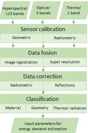
The designed workflow consists of firstly calibrating the sensors, using a designed multimodal calibration pattern. Next step of the workflow is the data fusion, which consists of different ap-proaches depending on the types of data. Different apap-proaches in terms of image registration and super resolution need to be addressed, due to the different radiometric and geometric resolu-tions. In addition, data corrections such as radiometric correction as well as identification and removal of reflections found in win-dows need to be dealt with. As a last step, classification of the facade elements which consists of firstly classifying the data sets on their own followed by classifying them as one data set, based on the material, geometry and the thermal radiation. The com-plete workflow can be seen in Figure 1 while each step of the chain is described in detail in the following subsections.
Figure 1. Proposed workflow
2.1 Calibration
A common approach for doing sensor calibration of optical sys-tems is by using a checkerboard pattern. However, since the checkerboard pattern is not visible in the spectrum of thermal in-frared, it is not possible to utilize regular checkerboard patterns for thermal sensors. Geometric calibration of thermal sensors is therefore often done by utilizing a pattern consisting of lamps (Lag¨uela et al., 2011a, Weinmann et al., 2014, Ellmauthaler et
al., 2013). By creating a regular grid of lamps, the possibility of using standard calibration procedures for sensors is enabled.
Another approach for camera calibration is the usage of circles (Heikkila, 2000), which can be utilized for calibration of thermal sensors as well (Luhmann et al., 2013, Yu et al., 2013). A pat-tern consisting of circles can be of use for calibration of a multi-modal system, since the circles and the background could consist of different material that have different emissivities. This could be exploited for calibration of a thermal camera.
A calibration pattern which can be used for geometric calibration of both a thermal sensor and an optical sensor needs to fulfill spe-cific requirements. Calibration of a thermal sensor relies on tem-perature differences between the grid points and the background which is not the case for calibration of optical sensors. However, to save time and effort, a calibration pattern which can be used for multimodal systems would be of value.
Radiometric calibration has to be done for validation of the ac-quired data, i.e. the received pixel values. This can be done by either using a contact thermometer or a spectrometer, depending on which sensor is set to be radiometric calibrated.
2.2 Data fusion
Due to handling three kinds of sensors with different spatial reso-lution and field of view in addition to the acquired data being ex-pressed in different physical units and bit depths, the data fusion needs to be addressed differently depending on the sensor. Data acquired with the optical and the hyperspectral sensor can essen-tially be approached the same while dealing with data fusion, but data acquired with the thermal sensor needs to be approached dif-ferently. First off, the thermal sensor acquire data in a single band compared to the two other sensors and the pixel values are repre-sented as thermal radiation, in K. Additionally, features that are easily detected in optical images, such as edges, appear blurred in thermal infrared images. Hence, commonly used data fusion algorithms for optical systems, such as the Scale Invariant Fea-ture Transform (SIFT) (Lowe, 1999), are not suitable for thermal images (Gonz´alez-Aguilera et al., 2013).
Three sets of data will be collected with the UAV which need to be registered and fused onto each other. Firstly, image registra-tion needs to be performed for each separate set, meaning the data collected with the optical sensor need to be registered on its own. After each data set has been registered separately, the three data sets need to be registered to each other. Depending on the data set, the image registration needs to be addressed differently.
As for the final image registration of three data sets, control points are often used (Turner et al., 2014, Weber et al., 2015, Gonz´alez-Aguilera et al., 2013). The control points can either be artificial, meaning that they are manually selected in the images during the registration, or they can be real points marked in the images. However, since the image registration will be done on images of building facades, it is difficult to use real control points since some locations of buildings facades are unreachable. Hence, ar-tificial control points will be utilized.
UAV based sensor system can often not offer images of a high radiometric and geometric resolution. The camera systems are designed to be as small as possible and therefore, the techni-cal specification may suffer in comparison to bigger camera sys-tems. Bigger sensors have often a push-broom scanner, which makes it possible to acquire images of high resolution, but need sophisticated methods for a reasonable orthorectification, while snapshot sensors on the other hand have a low resolution (Habib et al., 2017). Additionally, a UAV based sensor does not have space for a cooling system, which degrades the radiometric per-formance. Hyperspectral and thermal sensors designed for UAV system have a lower pixel resolution in comparison to standard RGB cameras. To retrieve as much information from these low-resolution images as possible, it would be of interest to improve their pixel resolution. Additionally, instead of dealing with three different data sets with three different radiometric and geometric resolutions, it would be desirable to have the merged data at same resolution as the sensor with the highest resolution.
Super resolution is the concept of improving the pixel resolution of low resolution images, which can be done by using one single image (Dong et al., 2016, Glasner et al., 2009) or by exploit-ing the resolution in one high resolution image to improve a low resolution image (Zomet and Peleg, 2002). Since this presented concept will use three sensors, one being an optical sensor with a higher pixel resolution than the other two sensors, it would be of benefit to improve the resolution of the other two data sets. By exploiting the high-resolution imagery of the optical sensor, it is possible to improve the resolution of the thermal and the hy-perspectral sensor by using the second approach. Hence, the two low-resolution data sets can be improved by utilizing and extract-ing information from the optical sensor.
2.3 Data correction
Radiometric correction has to be done to correct the collected data, i.e. the pixel values. As the data is collected outdoors, where there is often an alternation between direct sunlight and clouds, the varying solar radiation needs to be corrected. Cor-rection of the atmospheric effect is not needed since the distance between the building facades and the UAV is negligible in stan-dard applications.
This is significant while dealing with the classification of the hy-perspectral data, since classification of materials depends heav-ily on spectral reflectance. The correction can be done by ei-ther adjusting the collected data with the corresponding spectral reflectance collected from existing spectral libraries or with the collected data with a spectrometer in combination with informa-tion about the intensity of the solar radiance. However, in order to correct the hyperspectral data based on spectral libraries, the fa-cade material needs to be known. If unknown, the correction has to be based on the collected data from a spectrometer in addition to measured sun radiation.
Radiometric correction of the emissivity of facade materials needs to be addressed, which can only be done if the material is known. In comparison to the hyperspectral data, the collected data from the thermal sensor cannot be validated by comparing it to an ex-isting data base. Therefore, the correction has to be purely de-pendent on the acquired additional data about the solar radiance.
Since dealing with facades, reflections in windows appear, both in the thermal and in the optical images, which is affecting the clas-sification. If the reflections remain in the window, classification can result in false statements. Parts of a window may be classified into another material, causing an incorrect material classification of a window. In addition, this may cause issues when dealing with object detection of the facade, since parts of the window might not be considered to be a part of the object. Hence, the reflections need to be addressed.
2.4 Multi-image 3D reconstruction
To distinguish the building facades from their surroundings, a 3D model would be of use. This would enable the possibility to re-move or ignore undesirable features seen in the images, such as cars and trees since the aim is to classify facade elements. In ad-dition, generating a 3D model would provide a depth to the scene, which could be exploited to distinguish, e.g. balconies from the actual building facade.
A common approach to generate 3D models of facades is with the use of a laser scanner, which can be merged with thermal data to generate thermal 3D models (Weinmann et al., 2014, Borrmann et al., 2013). However, since a laser scanner will not be used for this concept, another method has to be approached. The Semi Global Matching (SGM) algorithm (Hirschm¨uller, 2008) can generate a 3D model by matching several panchromatic images captured at different viewing angles from a single flyby. Since the UAV sys-tem will have an optical camera with a high pixel resolution, it would be possible to utilize the optical images to generate a dense 3D model.
An approach to generate dense surface models of building fa-cades with the usage of thermal images in combination with op-tical images has been proposed in a study by (Gonz´alez-Aguilera et al., 2013). A pair-wise matching technique with the support of SGM was used to generate a 3D model of a building facade, which can be done after fusing the acquired thermal images with the optical images. This approach will be used in this study for generation of 3D models of building facades, since it has proven to result in good 3D models of building facades and by using a multimodal system.
2.5 Classification of facade elements
Once the data sets have been co-registered and fused, the final classification can be approached which consists of classifying el-ements based on the material, geometry and the thermal radiation. However, before the final classification with the three parameters can be determined, the separate data sets need to be classified.
Commonly used pixel based classification algorithms that would be suitable for classification of the hyperspectral as well as the thermal data set is Support Vector Machine (SVM) and Random Forest (RF), since they do not require a large data set to achieve a sufficient classification. Convolution Neural Network (CNN) on the other hand would require a large data set for training of the network, which could be utilized in later stages of the study for potential improvement of the classifications.
The classification of the facade material using the acquired hyper-spectral data will utilize hyper-spectral libraries for acquiring informa-tion about facade materials. CNN could be used for classificainforma-tion of the facade material if a large enough data set is available. How-ever, if the available spectral libraries do not contain the spectral reflectance of the building material which is collected throughout the study, it is not feasible to use CNN since the data set is not large enough.
To extract objects from the facades based on their geometry, a standard image segmentation approach is sufficient. The segmen-tation of facade objects will be based on the optical data set, since it will be of a higher resolution. However, certain objects of in-terest might appear clearer in the thermal infrared images, such as windows and ventilations due to the temperature difference. Window detection in thermal images can be approach using the method proposed in (Iwaszczuk, 2015), by searching for win-dows using designed window and facade models. This approach could be adapted, meaning more models could be designed for detection of e.g. ventilations.
3. SENSORS
The three sensors that have been selected to be used for the real-ization of the concept are all a size suitable for a UAV, with the hyperspectral sensor being the heaviest.
The optical camera is the Mapir Survey2 with a pixel resolution of 4608×3456 pixels. The lens has a field of view of 82◦and a focal ration of f/2.8. The camera operates in the standard RGB spectrum and has a weight of 64 g with accompanied battery.
FLIR Tau2 640 LWIR is the chosen thermal infrared sensor, which has an uncooled VOx microbolometer. The sensor records in the wavelength range of 7.5 to 13.5µm with a pixel resolution of 640×512 pixels and is able to measure temperatures
rang-ing from -25 to 135◦C. The instant field of view of the sensor is 1.3 mrad with a corresponding field of view of 45◦
×37◦.
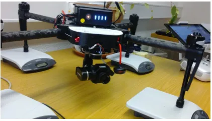
Figure 2. FLIR Tau2 640 LWIR attached on the drone DJI Matrice 100
The hyperspectral sensor is the S185 FireflEYE SE which uses snapshot mode for acquisition of images. The acquisition time for
one cube is 1/1000 of a second, using a CCD detector. The sen-sor has a wavelength range of 450 - 950 nm, 125 spectral bands, a spectral resolution of 8 nm at 532 nm and a pixel resolution of 50 x 50. The sensor weights 840 g including accompanied equip-ment, which is still suitable for a UAV. In addition to the 125 bands, one panchromatic band exists which acquire an image with a resolution 1000 x 1000 pixels.
By comparing the three sensors, it is noticeable that the pixel res-olution varies. The Survey2 has the highest resres-olution, making it suitable for generating a 3D model of the building facades. It can be used as well to improve the resolution of the two other sensors, since it is desirable to have the same pixel resolution in the three data sets. The FireflEYE sensor has a significant lower pixel resolution compared to the two other sensors, which has to be addressed by either using super resolution and exploiting the resolution of the optical data set or by using a sharpening algo-rithm on the data set on its own. However, since the pixel res-olution differ by a factor of around 90 between the optical and the hyperspectral sensor, it might not be feasible to impose super resolution. Sharpening of the data collected with the hyperspec-tral sensor using the panchromatic image while downscaling the resolution of the optical sensor might be more feasible.
4. REALIZATION OF THE CONCEPT
As a first step towards realizing the concept, geometric calibra-tion has been done with the thermal sensor using the designed cal-ibration pattern. The approach is described in Section 4.1 while the calibration results are presented in Section 4.2.
4.1 Geometric calibration
To save time and effort while dealing with a multimodal system by not having to use several calibration patterns, it was desired to have one single calibration pattern which can be used for different kinds of sensors. Therefore, a calibration pattern designed for a multimodal system, i.e. for a system which uses both thermal and optical sensors, was set to be designed.
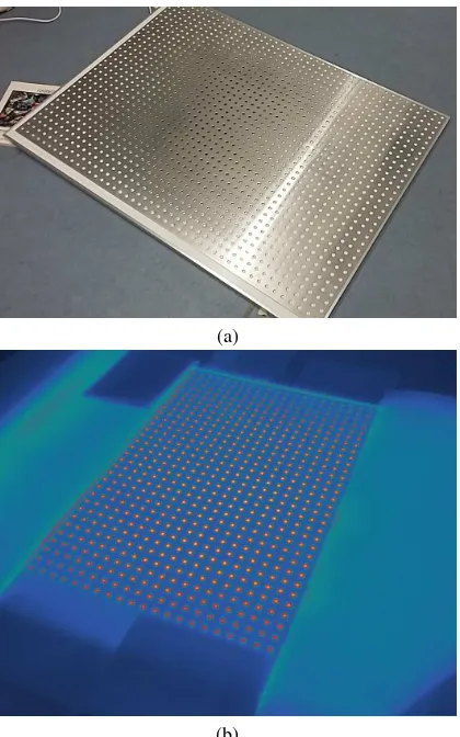
The designed pattern consists of an infrared heating plate and an aluminum sheet with cropped out circles which is placed on top of the heating board, as seen in Figure 3. The utilized infrared heating plate is TIH 1100 S, with a heating capacity of 1.1 kW and a surface temperature, when heated, of 70 to 90◦C. The alu-minum sheet was delivered with cropped out circles with diame-ter of 10 mm and with a circle cendiame-ter distance of 25,98 mm.
To test the designed pattern, calibration was carried out with a thermal sensor FLIR Tau2 640 LWIR.
(a)
(b)
Figure 3. The designed calibration pattern (a) and how the pattern is shown in the thermal infrared domain (b)
adjusted for detection of centers of circles and for using thermal images. The original workflow of the calibration toolbox was kept the same, but the procedure for extraction of the grid points was changed to detect circle centers instead.
The four extreme circle centers have to be selected by the user, just like in the original version, to determine the true extreme cir-cle centers. The true circir-cle centers are determined by creating a search area around each selected point and within the search area, detect a small circular shaped blob with an intensity maximum, i.e. different emissivity than its surroundings. This determina-tion of circle centers could be approached since the heating pat-tern underneath the aluminum plate has another emissivity, hence the circle appears to have another emissivity than the aluminum plate. Therefore, the true circle points could be determined by exploiting the thermal radiance which can be detected in thermal infrared images, by using the emissivity differences.
Once the four true extreme circle centers were determined, the remaining circle centers were determined using the same proce-dure, i.e. using the emissivity difference to determine blobs.
4.2 Geometric calibration results
For testing of the designed multimodal calibration pattern, cali-bration of the thermal sensor FLIR Tau2 640 LWIR was done. Due to the size and the weight of the calibration pattern, the pat-tern was stationary while the sensor was moved around. Images were captured at different orientations relative to the sensor, with
the aim to acquire images from as many different points of views as possible.
20 images that had been captured with the thermal infrared sensor were chosen to be used for calibration. The images were picked on the basis that they should cover as much of the image frame as possible, see Figure 4 for one chosen image. Out of the 20 images, 5 were omitted during iteration due to undesirable esti-mations of the calibration parameters. The geometric calibration results can be found in Table 1, where the focal length is pre-sented in the amount of pixels along the x and y axis, the two first coefficients of the calculated distortion effect and the mean standard deviation in the amount of pixels along the x and y axis.
Figure 4. Determined grid points
The results indicate that the designed pattern can be used for cal-ibration of thermal sensor, since there is a clear emissivity differ-ence between the circles and the aluminum plate.
5. CONCLUSION AND FUTURE WORK
In this paper, a concept for classification of facade elements us-ing a multimodal UAV system was presented. The introduced concept consists of calibrating the sensors, followed by fusing the data acquired with the different sensors. The workflow con-tinues with processing the data and finally classifying it in terms of geometry, material and thermal radiation. As a first step of the concept, results from the geometric calibration with the thermal sensor, using a designed multimodal pattern, were presented.
The camera calibration toolbox needs to be adapted for other types of sensors for future use. At the moment, the toolbox de-tects circle centers exploiting the emissivity difference between the heating plate and the aluminum plate. The first calibration results using the designed pattern indicates that the pattern can be used for multimodal systems. To perform calibration with an optical sensor with the same calibration pattern, the determina-tion of the circle centers cannot be based on the temperature dif-ference. Therefore, the toolbox needs to be adapted depending on which sensor is being used. However, tools and algorithms for detection of circles in optical images exist which makes the adaptation doable.
Table 1. Geometric calibration results
1 756.2, 777.0 -0.056, 0.300 0.32, 0.36
2 754.5, 774.6 -0.061, 0.378 0.54, 0.51
3 753.7, 769.6 -0.058, 0.353 0.51, 0.51
4 757.0, 776.2 -0.052, 0.274 0.33, 0.35
5 787.4, 781.2 0.000, 0.039 0.31, 0.36
Mean value 761.8, 775.6 -0.045, 0.205 0.402, 0.418
for estimation of the energy demand, such as exploiting the ge-ometrical information of a building, could improve the energy demand estimations.
ACKNOWLEDGEMENT
The authors would like to thank Nimet Karag¨oz for the support given during the calibration of the thermal sensor. This work is a part of the research cluster URBAN-SAT, a part of the graduate school GRACE.
REFERENCES
Balaras, C. A. and Argiriou, A. A., 2002. Infrared thermography for building diagnostics. Energy and Buildings34(2), pp. 171– 183.
Borrmann, D., Elseberg, J. and N¨uchter, A., 2013. Thermal 3D mapping of building fac¸ades. Intelligent autonomous systems 12 pp. 173–182.
Bouguet, J.-Y., 2004. Camera calibration toolbox for matlab.
Carrio, A., Pestana, J., Sanchez-Lopez, J.-L., Suarez-Fernandez, R., Campoy, P., Tendero, R., Garc´ıa-De-Viedma, M., Gonz´alez-Rodrigo, B., Bonatti, J., Rejas-Ayuga, J. G., Mart´ınez-Mar´ın, R. and Marchamalo-Sacrist´an, M., 2016. Ubristes: UAV-based building rehabilitation with visible and thermal infrared remote sensing. In: Robot 2015: Second Iberian Robotics Conference, Springer, pp. 245–256.
Dong, C., Loy, C. C., He, K. and Tang, X., 2016. Image super-resolution using deep convolutional networks.IEEE Transactions on Pattern Analysis and Machine Intelligence38(1), pp. 295– 307.
Ellmauthaler, A., da Silva, E. A. B., Pagliari, C. L., Gois, J. N. and Neves, S. R., 2013. A novel iterative calibration approach for thermal infrared cameras. In:Image Processing (ICIP), 2013 20th IEEE International Conference on, IEEE, pp. 2182–2186.
Glasner, D., Bagon, S. and Irani, M., 2009. Super-resolution from a single image. In: Computer Vision, 2009 IEEE 12th Interna-tional Conference on, pp. 349–356.
Gonz´alez-Aguilera, D., Lag¨uela, S., Rodr´ıguez-Gonz´alvez, P. and Hern´andez-L´opez, D., 2013. Image-based thermographic modeling for assessing energy efficiency of buildings fac¸ades. Energy and Buildings65, pp. 29–36.
Habib, A., Xiong, W., He, F., Yang, H. L. and Crawford, M., 2017. Improving orthorectification of uav-based push-broom scanner imagery using derived orthophotos from frame cameras. IEEE Journal of Selected Topics in Applied Earth Observations and Remote Sensing10(1), pp. 262–276.
Heikkila, J., 2000. Geometric camera calibration using circular control points. IEEE Transactions on Pattern Analysis and Ma-chine Intelligence22(10), pp. 1066–1077.
Hirschm¨uller, H., 2008. Stereo processing by semiglobal match-ing and mutual information.IEEE Transactions on Pattern Anal-ysis and Machine Intelligence30(2), pp. 328–341.
Iwaszczuk, D., 2015. Automatic Texturing of 3D Models of Ur-ban Areas Using Image Sequences from Airborne TIR Cameras. PhD thesis, Technical University Munich.
Kaden, R. and Kolbe, T. H., 2013. City-wide total energy demand estimation of buildings using semantic 3D city models and statis-tical data.ISPRS Annals of the Photogrammetry, Remote Sensing and Spatial Information Sciences2, pp. 163–171.
Lag¨uela, S., Gonz´alez-Jorge, H., Armesto, J. and Arias, P., 2011a. Calibration and verification of thermographic cameras for ge-ometric measurements. Infrared Physics & Technology54(2), pp. 92–99.
Lag¨uela, S., Mart´ınez, J., Armesto, J. and Arias, P., 2011b. En-ergy efficiency studies through 3D laser scanning and thermo-graphic technologies. Energy and Buildings43(6), pp. 1216– 1221.
Lowe, D. G., 1999. Object recognition from local scale-invariant features. In:Computer vision, 1999. The Proceedings of the 7th IEEE International Conference on, Vol. 2, IEEE, pp. 1150–1157.
Luhmann, T., Piechel, J. and Roelfs, T., 2013. Geometric cali-bration of thermographic cameras. In:Thermal Infrared Remote Sensing, Springer, pp. 27–42.
Mastrucci, A., Baume, O., Stazi, F. and Leopold, U., 2014. Esti-mating energy savings for the residential building stock of an en-tire city: A GIS-based statistical downscaling approach applied to Rotterdam.Energy and Buildings75, pp. 358–367.
Morel, J.-M. and Yu, G., 2009. ASIFT: A new framework for fully affine invariant image comparison. SIAM Journal on Imag-ing Sciences2(2), pp. 438–469.
Ribari´c, S., Marˇceti´c, D. and Vedrina, D. S., 2009. A knowledge-based system for the non-destructive diagnostics of fac¸ade isola-tion using the informaisola-tion fusion of visual and IR images.Expert Systems with Applications36(2), pp. 3812–3823.
Turner, D., Lucieer, A., Malenovsk`y, Z., King, D. H. and Robin-son, S. A., 2014. Spatial co-registration of ultra-high resolution visible, multispectral and thermal images acquired with a micro-UAV over antarctic moss beds. Remote Sensing6(5), pp. 4003– 4024.
Weber, I., Jenal, A., Kneer, C. and Bongartz, J., 2015. Pantir-a dual camera setup for precise georeferencing and mosaicing of thermal aerial images.The International Archives of Photogram-metry, Remote Sensing and Spatial Information Sciences40(3), pp. 269.
Yu, Z., Lincheng, S., Dianle, Z., Daibing, Z. and Chengping, Y., 2013. Camera calibration of thermal-infrared stereo vision sys-tem. In: Intelligent Systems Design and Engineering Applica-tions, 2013 Fourth International Conference on, IEEE, pp. 197– 201.