MODUL
2
KEBAIKAN KERJA DAN
KEBAIKAN KERJA DAN
CARA PEMAKAIAN
ALAT UKUR VOLT &
AMPER
AMPER
2 Pada Modul ini Saudara akan Membahas
2. Pada Modul ini Saudara akan Membahas
tentang:
2 1 Kesalahan-kesalahan
2.1. Kesalahan-kesalahan
2.2. Batas Kesalahan dari Alat Ukur
2 3 S b b
b b k
l h d i Al t Uk
2.3. Sebab-sebab kesalahan dari Alat Ukur
2.4. Pemakaian Daya sendiri Alat Pengukur
2.5. Cara- menghubungkan Alat Pengukur
Amper dan Alat Pengukur Volt
2.6. Pengukuran dari Arus Besar
2.7. Pengukran Arus–arus kecil
2 1 Kesalahan Kesalahan
3
2.1 Kesalahan-Kesalahan
Untuk Mengetahui kebaikan kerja dari salah satu
Untuk Mengetahui kebaikan kerja dari salah satu
alat ukur maka KESALAHAN dijadikan salah satu
ukuran yang penting.
y g p
g
Kesalahan alat ukur dinyatakan dengan rumus
b ik
berikut:
M – T = ε
(Kesalahan Alat Ukur)M T
ε
(Kesalahan Alat Ukur)T = Hrg yg sbnrnya dr kebesaran alat ukur (Komponen yg di ukur) kaitannya “ketelitian” M = Hrg yang di dpt dr pengukuran menggunakan AU (pembacaan nilai/data pengukuran)
kaitannya “ketepatan”y p
% ; Kesalahan relatif/Ratio kesalahan/
Kesalahan
Persentuil
/
Kesalahan
=
ε / T
T – M = α
(Koreksi)T M
α
(Koreksi)% ; Ratio koreksi/koreksi relatif/harga numerik/
Koreksi
Persentuil
/
Koreksi = α / M
Persentuil
/
Koreksi
α / M
Misal : T = 25,0 A M = 24,3 A
% ε
atau
% α
Adalah
± 0,7 atau
2,8% dan
2,9%
± 0,7 atau
2,8% dan
2,9%
Jadi apa yg dimaksud dengan
J
p yg
g
Pengukuran yg Teliti ?
24/03/2008 http://yasdinulhuda.wordpress.com
5
Ketelitian
:
Menyatakan tk kesesuaian / dekatnya hsl pengukuran thd hrg
Menyatakan tk kesesuaian / dekatnya hsl pengukuran thd hrg
sebenarnya
Ketepatan
p
:
Menyatakan tk kesamaan di dlm seklp pengukuran/sejumlah instrumen
Suatu indikasi dari ketepatan pengukuran diperoleh
Suatu indikasi dari ketepatan pengukuran diperoleh
dari banyaknya angka-angka yang berarti
(
significant figures
)
(
g f
f g
)
Angka-angka yang berarti ini memberikan
informasi yang nyata (
actual
) mengenai
kebesaran dan ketepatan pengukuran.
Makin banyak angka angka yang berarti, ketepatan
k
j di l bih b
Contoh
:
R
68
Ω
Jika;
R = 68 Ω
Artinya tahanan ini akan lebih mendekati 68 Ω, dari pada 67Ω atau 69 Ω
Jika;
R = 68,0 Ω
Berarti Nilai Tahanan ini akan lebih mendekati 68,0 Ω, dari pada 67,9Ω
68 1 Ω
atau 68,1 Ω
Pada Tahanan 68 Ω terdapat 2 angka yang berarti, sedangkan pada Tahanan 68,0 Ω
memiliki 3 angka yang berarti. Jadi...
Tahanan 68,0 Ω memiliki angka berarti yang lebih banyak, artinya mempunyai ketepatan yang lebih tinggi daripada tahanan 68 Ω
Alasannya ...??
Sebaiknyanya untuk mencatat suatu hsl pengukuran dgn menggunakan
Sebaiknyanya untuk mencatat suatu hsl pengukuran dgn menggunakan
semua angka yang kita yakini paling mendekati ke harga sebenarnya.
Cara lain menyatakan hsl pengukuran ini adalah
Cara lain menyatakan hsl pengukuran ini adalah
menggunakan
Rangkuman Kesalahan yang mungkin
g
y
g
g
(range of possible error)
Sehingga tegangan di atas dpt ditulis:
117,1 ± 0,05 Volt
; (117,05 Volt dan 117,15 Volt)
Dan
Untuk mendapatkan hasil yg paling baik “paling
d k t d
h
b
”
dekat dengan harga yg sebenarnya”
Nyatakanlah dalam
NILAI RATA-RATA
dari semua
pembacaan
pembacaan
Penyelesaian:
N
E
E
E
E
1+
2+
3+
4=
03
11
08
11
11
11
02
11
(a). E
rata-ratay
06
,
117
4
03
,
117
08
,
117
11
,
117
02
,
117
=
+
+
+
=
(b). Rangkuman
E
maksimum– E
rata rata= 117,11 – 117,06 = 0,05 V
(b). Rangkuman
E
maksimumE
rata‐rata117,11 117,06 0,05 V
Tetapi juga
E
rata‐rata‐ E
minimum= 117,06 – 117,02 = 0,04 V
Maka Rangkuman Kesalahan Rata-rata Menjadi :
V
V
0
04
045
0
04
,
0
05
,
0
+
=
±
=
±
=
=
±
0
,
045
V
=
±
0
,
04
V
=
Standar IEC no. 13B-23 Menspesifikasikan
bahwa
“Ketelitian ketelitian
dari
AU
bahwa
“Ketelitian-ketelitian
dari
AU
kumparan putar harus diberikan menurut
klasifikasi dalam
-
8 Class
-” yaitu:
klasifikasi dalam
8 Class
yaitu:
±0,05%
±0,1% ±0,2%
±0,5%
±1%
±1 5%
±2 5%
±5%
±1%
±1,5%
±2,5%
±5%
Hal ini maksudnya yaitu; Bahwa kesalahan dari
l
k
kl f k
d
d l h
alat ukur menurut klasifikasi di atas, adalah
dalam batas-batas ukur penting seharusnya
ada dalam batas batas masing masing
ada dalam batas-batas masing-masing
Klasifikasi-klasifikasi di atas digolongkan dalam 4 (empat) golongan
d
k t li
d
k
i i
b b d
(B
h l
19 d
dengan
ketelian dan kepresisian yang berbeda
(Baca halaman 19 s.d
20 Buku 1)
Medan Magnit Luar
Temperatur Keliling
p
g
Pemanasan Sendiri
Pergeseran dari titik Nol
Pergeseran dari titik Nol
Gesekan-gesekan
Umur
K
ki
k
ki
k
b ik t
d l h
Kemungkinan-kemungkinan
pengukuran
berikutnya
adalah
apabila suatu alat ukur yang memerlukan pemakaian daya
sendiri yang cukup besar, dihubungkan pada jaringan-jaringan
pengukuran
yang
mengintroduksikan
kesalahan-kesalahan,
sehingga apa yang diukur akan mungkin banyak berbeda dari
pada kebesaran yang sebenarnya harus didapatkan dari
p
y g
y
p
pengukuran.
Contoh:
Prinsip Hukum Ohm
Alat ukur yang digunakan untuk mengukur besarnya
tahanan dinamakan ohmmeter. Prinsip kerja alat ini
berdasarkan hukum Ohm
Ketika suatu ampermeter
berdasarkan hukum Ohm. Ketika suatu ampermeter
dihubungkan langsung dengan sumber tegangan maka
rangkaian peralatannya adalah seperti pada gambar di
atas
Pengukuran Tahanan dengan Ohmmeter
Pada rangkaian seperti pada gambar di atas dapat
diketahui bahwa kuat arus yang mengalir menjadi kecil (I’
< I). Dari pengurangan penunjukan skala kuat arus
)
p
g
g
p
j
tersebut dikonversikan sebagai penambahan tahanan yang
diukur. Oleh karena itu cara penunjukkan skala dalam
Ohmmeter adalah dari kanan ke kiri.`
Pengukuran Tegangan
Pengukuran Tegangan
Voltmeter harus memiliki tahanan alat ukur yang besar, agar
tidak menarik arus yang kuat, sebab akan mengakibatkan
t r nn a
tegangan
s mber
ar sn a
Selain
it
akan
turunnya
tegangan
sumber
arusnya.
Selain
itu
akan
menyebabkan kehilangan tegangan tambahan pada hantaran
penghubungnya. Tetapi pada kenyataannya voltmeter tidak
memiliki tahanan yang besar, maka untuk memenuhi fungsinya
sebagai voltmeter perlu ditambahkan tahanan depan yang
dihubungkan seri dengan pesawatnya.
+
I
1I
2R
1R
1−
a
b
R
3R
xDalam metode ini hambatan R1 dan R2 dibuat tetap sedangkan
hambatan Rs dapat dikalibrasi. Hambatan Rs diatur besarnya sedemikian
rupa sehingga galvanometer menunjukkan angka nol (tidak ada arus yang
melaluinya), keadaan ini dikatakan jembatan seimbang. Pada kondisi
i b
i ik P d
Q
i
i l
hi
b d
seimbang, titik P dan Q mempunyai potensial yang sama, sehingga beda
potensial untuk R1 sama dengan Rs dan beda potensial R2 sama dengan
Rx.
Rasio kedua persamaan tersebut adalah:
Pada jembatan Wheatstone yang seimbang,
jarum galvanometer menunjukkan angka nol,
hasil kali hambatan yang saling bersilangan sama
hasil kali hambatan yang saling bersilangan sama
besar.
Arus beban besar Arus beban Kecil Arus beban besar Arus beban Kecil
Cara pengukuran menurut bagan (a) ternyata bahwa arus yang ditunjukkan
oleh amperemeter yaitu Ia besar Ia = Iv + Ib. Berarti besar arus yang
ditunjukkan oleh amperemeter menjadi terlampau besar yang seharusnya
ditunjukkan oleh amperemeter menjadi terlampau besar yang seharusnya
besarnya Ib. Oleh karena itu pada penunjukkan daya tersebut terdapat
kesalahan.
Apabila pengukuran dilaksanakan seperti gambar (b), maka tegangan yang
p
p g
p
g
( ),
g g
y g
ditunjukkan voltmeter menjadi Ev = Ea + Eb, sehingga dayanya Wb = Ev
Ib atau Wb = (Ea + Eb )Ib yang seharusnya besar daya Wb = Eb . Ib, jadi
penunjukan daya tersebut tetap lebih besar dari yang seharusnya
Two Types of Multimeters
DMM
(digital)
VOM
(analog)
Types of Meters
Analog meter:
|
Uses a moving pointer and a printed scale to indicate
values of voltage, current, or resistance.
Volt-Ohm-Milliammeter (VOM):
Volt Ohm Milliammeter (VOM):
|
Allows all three kinds of measurements on a single
scale or readout.
Digital multimeter:
|
Uses a numerical readout to indicate the measured
value of voltage current or resistance
value of voltage, current or resistance.
Direct Current Meters
Direct current in a moving-coil meter deflects
th i t
i
ti
t
th
t f
the pointer in proportion to the amount of
current.
A current meter must be connected in series with
the part of the circuit where the current is to be
p
measured.
A dc current meter must be connected with the
Analog instruments use a moving coil meter movement.
Current flow in the coil
moves the pointer
up-scale
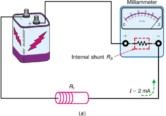
Meter Shunts
Meter shunts are low-value precision resistors
th t
t d
i ll l
ith
th t
that are connected in parallel with the meter
movement.
Meter shunts bypass a portion of the current
around the meter movement. This process
p
extends the range of currents that can be read
with the same meter movement.
Using Shunts to Increase Ammeter Range
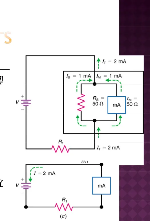
Fig 8 4: Example of meter shunt R in bypassing current around the movement to extend Fig. 8-4: Example of meter shunt R in bypassing current around the movement to extend
V
M= I
Mx r
MI
S
= I
T- I
MR
S=
V
MI
SV
M= 50mV
I
S= 1 mA
R
S= 50 Ω
Fig. 8-4: (b) Schematic diagram showing effect of shunt. With RS = rM the current range is
doubled (c) Circuit with 2-mA meter to read doubled. (c) Circuit with 2 mA meter to read the current.
I 0 005 0 001 0 004 A 4 A
I
S= 0.005 − 0.001 = 0.004 A or 4 mA
Divide V by I to find R
Divide V
Mby I
Sto find R
S.
A voltmeter is connected across two points to
measure their difference in potential.
A voltmeter uses a high resistance multiplier in
A voltmeter uses a high-resistance multiplier in
series with the meter movement.
A dc voltmeter must be connected with the
A dc voltmeter must be connected with the
A multiplier resistor is a large resistance in
series with a moving coil meter movement
series with a moving-coil meter movement
which allows the meter to measure voltages
in a circuit
Using Multipliers to Increase
Voltmeter Range
Using Multipliers to Increase
Voltmeter Range
DCVVoltmeter Range
DCVVoltmeter Range
VM= IM x rM = 0.1 V 9.9 kΩ R mult VM= IM x rM = 0.1 V 9.9 kΩ R mult Sensitivity = rM VM = 1000 Ω per volt Rmult = VFS IM - rM 10 V Sensitivity = rM VM = 1000 Ω per volt Sensitivity = rM VM = 1000 Ω per volt Rmult = VFS IM - rM Rmult = VFS IM - rM 10 V 10 VFor a 25 V range, change Rmult to 24.9 kΩ.
Note: sensitivity is not affected by the multipliers
For a 25 V range, change Rmult to 24.9 kΩ.Note: sensitivity is not affected by the multipliers
Note: sensitivity is not affected by the multipliers.
Note: sensitivity is not affected by the multipliers.
Voltmeter Resistance
The high resistance of a voltmeter with
The high resistance of a voltmeter with
a multiplier is essentially the value of
the multiplier resistance.
the multiplier resistance.
Since the multiplier is changed for each
range, the voltmeter resistance changes.
range, the voltmeter resistance changes.
Ohms-per-Volt Rating
Analog voltmeters are rated in terms of the ohms
f
i t
i d f 1 V f d fl ti
of resistance required for 1 V of deflection.
This value is called the ohms-per-volt rating, or
the sensitivity of the voltmeter
the sensitivity of the voltmeter.
The ohms-per-volt rating is the same for all
ranges. It is determined by the full-scale current
g
y
I
Mof the meter movement.
The voltmeter resistance R
Vcan be calculated by
multiplying the ohms-per-volt rating and the
full-scale voltage of each range.
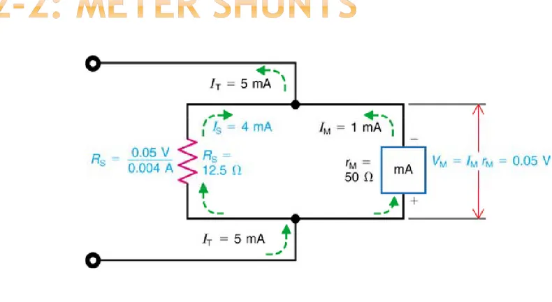
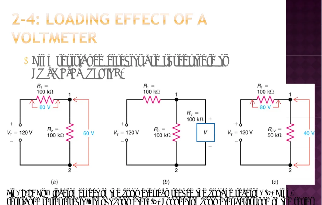
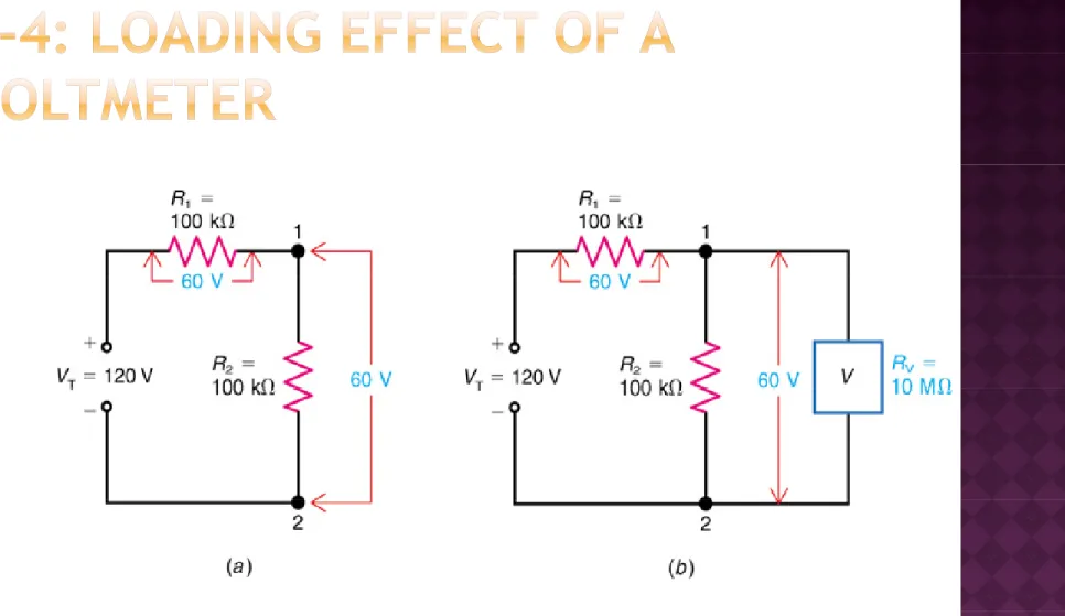
When voltmeter resistance is not high enough,
connecting it across a circuit can reduce the
measured voltage
measured voltage.
This effect is called loading down the circuit,
This effect is called loading down the circuit,
because the measured voltage decreases due to
the additional load current for the meter.
High resistance circuits are susceptible to
Voltmeter loading.
Fig. 8-8: How loading effect of the voltmeter can reduce the voltage reading. (a)
High-resistance series circuit without voltmeter. (b) Connecting voltmeter across one of the series resistances (c) Reduced R and V between points 1 and 2 caused by the voltmeter as a parallel resistances. (c) Reduced R and V between points 1 and 2 caused by the voltmeter as a parallel
Fig. 8-9: Negligible loading effect with a high-resistance voltmeter. (a) High-resistance series circuit without voltmeter (b) Same voltages in circuit with voltmeter connected because RV circuit without voltmeter. (b) Same voltages in circuit with voltmeter connected, because RV is so high.
Th l di ff t i i i i d b i
The loading effect is minimized by using a
voltmeter with a resistance much greater than
the resistance across which the voltage is
the resistance across which the voltage is
measured.
The loading effect of a voltmeter causes too low
l
di b
R i
l
a voltage reading because R
Vis too low as a
parallel resistance.
The digital multimeter (DMM) has practically no
The digital multimeter (DMM) has practically no
loading effect as a voltmeter because its input is
usually 10 to 20 MΩ on all ranges.
The following formula can be used to correct for
loading:
V V
[R R /R (R
R )]V
V = V
+ [R
R
/R
(R
+ R
)]V
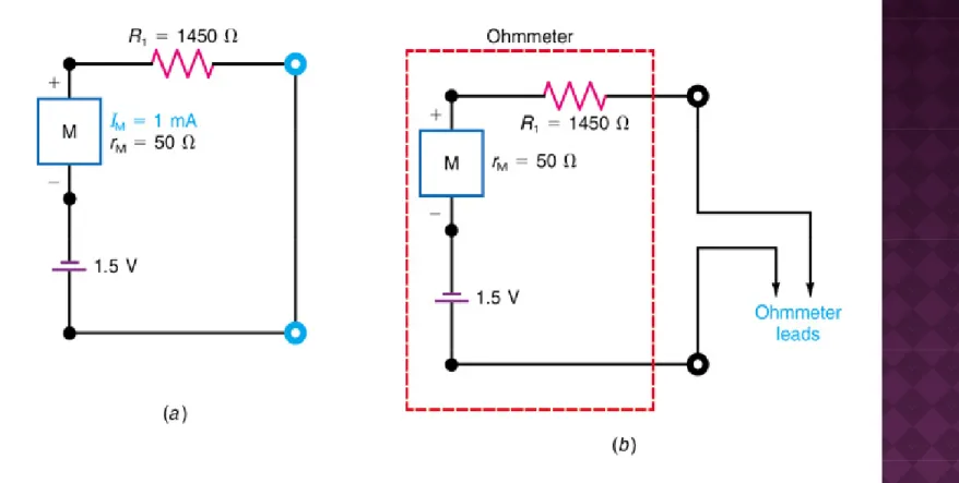
An ohmmeter consists of an internal battery in
series with the meter movement, and a current
limiting resistance
limiting resistance.
Power in the circuit being tested is shut off.
Current from the internal battery flows through
Current from the internal battery flows through
the resistance being measured, producing a
deflection that is:
|
Proportional to the current flow, and
|
Displayed on a back-off scale, with ohm values
increasing to the left as the current backs off from
increasing to the left as the current backs off from
full-scale deflection.
Fig. 8-10: How meter movement M can be used as an ohmmeter with a 1.5-V battery. (a)
Equivalent closed circuit with R1 and the battery when ohmmeter leads are short-circuited for zero ohms of external R (b) Internal ohmmeter circuit with test leads open ready to measure zero ohms of external R. (b) Internal ohmmeter circuit with test leads open, ready to measure
Resistance RT is the total resistance of RX and the ohmmeter’s
Fig. 8-11
Resistance RT is the total resistance of RX and the ohmmeter s internal resistance.
NOTE: RX is the external resistance to be measured.
h h ’ l 0 0 The ohmmeter’s internal resistance Ri is constant at 50 + 1450, or 1500 Ω here. If RX also equals 1500 Ω, RT equals 3000 Ω.
The current then is 1.5 V/3000 Ω, or 0.5 mA, resulting in half-The current then is 1.5 V/3000 Ω, or 0.5 mA, resulting in half scale deflection for the 1-mA movement.