Specialized Pr
ot
ection & Contr
ol
• Cost-effective, wireless and fast transfer trip solution • Transfers trip and status confirmation faster than standard
breaker reclose time
• Reliable and secure long distance transfer trip to multiple Distributed Generators
• Extremely resistant to interference due to frequency hopping spread spectrum technology
• Packaged & Engineered system tested to industry standards • Suitable for direct outdoor application
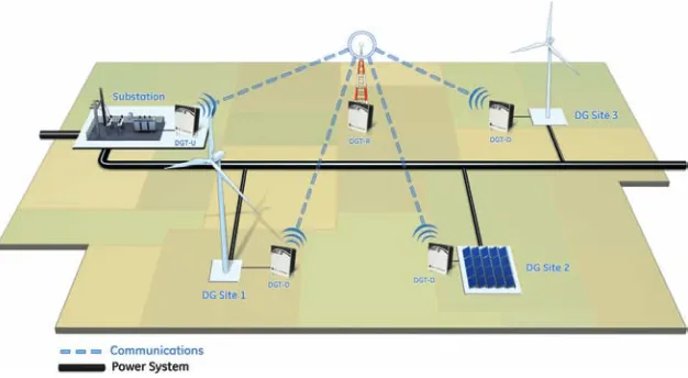
• Distributed Generation Trip Controls (DGT) are wireless communication devices used in applications that require transferring of trip signals from Power Distribution Utility Substations or Recloser Sites to multiple (1-7) Distributed Generators interconnected to the distribution grid.
Control EnerVistaTM Setup Software
• Separate setup software based on User application –Utility & Distributed Generator Owner.
• Single click option for quick connect to devices provides real-time feedback on device status.
• Single step configuration for DG Owner • Transfer trip issued from up to 2 locations on the feeder
- substation and recloser site
• Point to Multipoint: transfer trip issued to maximum 7 Distributed Generation sites
• Trip status of DG sites transferred back to utility substation and recloser site.
Communication
• Secure Communication: Frequency hopping spread spectrum technology
• High Speed: Transfer trip in 30 msec • Long distance: 30 mile range with Repeater • Reliable Communication: 32 bit CRC
• License free operation in the 902-928 ISM band (N. America) • 100% tested for RF performance -40 °C to +75 °C
• High Sensitivity: -106dBm @ 1x10-6 bit error rate
DGT
DISTRIBUTED GENERATION
TRIP CONTROL
Fast & Wireless trip of
Distributed Generators
FEATURES
APPLICATION
KEy BENEFITS
Specialized Pr
ot
ection & Contr
ol
Overview
The desire for green power and rapid developments in renewable energy sources are driving the growth of distributed generation. Many Power Distribution Companies are now encouraging small power producers to interconnect to the Utility grid. Independent power producers are typically customers who install small scale generating units up to 10 MW in size to offset their load and sell excess power to the local distribution Utility for grid support and reliable supply.
As Distributed Generation (DG) becomes more prevalent, DG interconnection to the Utility network requires an affordable, reliable, and high speed solution that can prevent power from being fed back to the grid during undesirable situations, such as power line maintenance, electrical faults, etc. In the event of a fault, the Distributed Generator needs to disconnect from the grid prior to the reclosing operation of the Utility Substation breaker.
The following factors determine the need for automatic Distributed Generation disconnect from the power grid when the substation breaker trips open:
• Safety Hazard: A power line assumed to be disconnected remains energized. This can be unsafe for the public, line personnel working on the feeder, etc. • Distributed Generation Damage: If a main
Utility breaker closes out of sync, the
Distributed Generator can be damaged • Customer equipment damage:
Frequency and voltage provided to customers can vary significantly and damage apparatus
GE Digital Energy is the industry leader in introducing a revolutionary and innovative Distributed Generation disconnect solution that is high-speed, cost-effective, wireless, long range, reliable and secure.
Transfer Trip Control
System
There are three types of Distributed Generation Trip Control (DGT) devices available for a wireless transfer trip system.
In a point-to-multipoint system, a first control device is required at the Utility Substation, a second control device between the substation and the generation site, and a third control device at each Distributed Generation site. A point-to-multipoint system can support up to 7 distributed generation sites.
However, in a point-to-point system, one control is installed at the Utility Substation and a second control at the Distributed Generation site. A point-to-point system supports one remote generation site.
Each DGT control device location is based on its respective function. The substation unit is required to transfer trip signals from the Utility Substation, the downstream control unit is needed to repeat the Substation trip signal to each DG site, and the DG site control device is needed to receive the trip signal from the substation and initiate the disconnect of the local breaker.
The following three controls complete the Distributed Generation Trip (DGT) Control network:
DGT-U
A DGT-U is a trip control device implemented at the Utility Substation for transferring wireless trip signals to remote DG sites (up to 7 sites) and receiving status notification back from each DG site after a trip operation has been completed. The transfer trip timing is 30 milliseconds.
Figure 1.
Distributed Generator feeds a faulted grid in the absence of a transfer trip solution. Figure 2.
Specialized Pr
ot
ection & Contr
ol
There is an option to locate a second DGT-U control at a recloser site on the distribution feeder. In this instance, the recloser sends a trip command to the remote DGT-D unit(s). The DGT-D then responds by initiating a trip and sending status confirmation back to the DGT-U at the recloser site and the DGT-U at the Substation.
DGT-R
A DGT-R is a Repeater device installed at or near the Utility Substation for coordinating wireless communication among the Utility and its various generation site(s). In a point to multipoint system, all communication is coordinated through the DGT-R unit in order to achieve a maximum distance of 30 miles and communicate with multiple generation sites.
DGT-D
A DGT-D is a trip control needed at the Distributed Generation site for receiving trip signals from the Utility Substation and sending a wireless status notification back to the Substation after a trip operation has been performed. The disconnect status transmit timing is 300 milliseconds.
The control devices in a DGT network continuously map data. The DGT-U and the DGT-D control units constantly transmit and receive an event (trip status =1) or a no event (no activity = 0) data between themselves via the DGT-R.
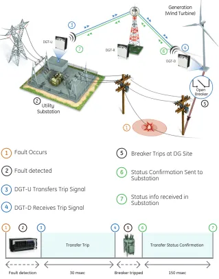
Distributed Generation Disconnect Sequence and Timing
The following steps describe how the application of DGT Controls enable safe and timely Distributed Generator disconnect from the Utility grid:
• Fault at power distribution line [1] • Substation relay detects the fault [2] • Relay triggers DGT-U Control device at
the substation to transfer a trip signal via Repeater control device (DGT-R) to remote distributed generation site [3] • Trip signal transferred in 30 milliseconds
from DGT-U to the remote site
• DGT-D Control unit at Distributed Generation site receives trip signal [4] • DGT-D triggers on site disconnect device
to trip
• Disconnect device (breaker, switch, etc) at DG site disconnects generator from the Utility grid [5]
• DGT-D Control at DG site transmits status confirmation back to Utility Substation via Repeater device DGT-R [6]
• Status confirmation transferred in 300 milliseconds from DGT-D to substation • DGT-U unit at substation receives status
confirmation info [7]
Wireless Technology
The DGT control provides highly reliable long-range communication over up to 30 miles. The DGT uses frequency hoppingspread spectrum radios that operate in the license free spectrum between 902 and 928 MHz. The radios hop between 128 channels with a bandwidth of 130 kHz. The frequency hopping technique makes the radios extremely resistant to interference. Frequency hopping also establishes a high level of security because data transmission occurs on a variety of frequencies in a random pattern. In addition, the DGT uses a 32-bit CRC algorithm to further insure security and reliability of data.
The DGT’s are able to operate in a point to multipoint configuration and transmit digital status among themselves at extremely high speeds. GE Digital Energy’s unique wireless data transmission
Fault Occurs
Fault detected
DGT-U Transfers Trip Signal
DGT-D Receives Trip Signal
1
3
4
2
Breaker Trips at DG Site
Status Confirmation Sent to Substation
Status info received in Substation
5
7 6
Figure 3.
Sequence and timing for isolating a Distributed Generator from a faulted grid.
Fault detection Breaker tripped
Transfer Trip Transfer Status Confirmation
30 msec 150 msec
Specialized Pr
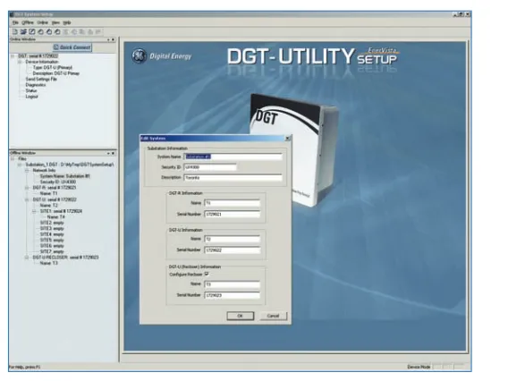
Using the DGT-Utility software a Utility user builds a DGT network. The software then creates encrypted data files that contain all necessary information and settings for the DGT-R and DGT-U devices. The DGT-Utility software also creates a DGT-D setting file to be sent to the distributed generation owner to authorize their DGT-D device to join the network. Only the utility can add DGT-D devices to a DGT Network. The configuration set up is simple with an online and offline menu available for ease of use. Configuration files are unique to each DGT network. A quick connect button allows the user to easily connect to the selected device.
DGT-DG Software
The Distributed Generation software allows User to upload a settings file or get diagnostics from a DGT-D control by simply clicking on the menu option. A quick connect button also allows the User to easily connect to the DGT-D device.
Enervista Launchpad
Enervista Launchpad is a powerful software package that provides Users with all the set up and support tools needed for configuring and maintaining GE Digital Energy DGT Controls. The set up software within Launchpad allows configuring devices in real time by communicating using serial connection or offline by creating setting files to be sent to devices at a later time.
Included in Launchpad is a document archiving and management system that ensures critical documentation is up to date and available when needed. Documents made available include:
• Manuals • Brochures • Wiring Diagrams technology allows transfer trip signals to
be sent and received by the end sites in 30 milliseconds.
While the DGT radios provide very robust wireless communication, radio line of site is needed to insure maximum range and performance. This path is achieved by mounting the DGT antenna at a suitable height above surrounding terrain and obstructions.
DGT system
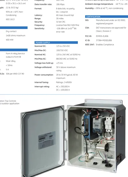
The DGT-U, DGT-R and DGT-D control devices are completely packaged units that include the appropriate DGT transceivers, power supply, necessary input and output terminations, antenna jumper cable and lightning protection in a weather resistant and lockable NEMA 4 enclosure.
The only connections required are for primary power, wiring to external devices (where necessary) and external antenna cable. All wiring connections are made within the enclosure leaving no connections exposed to environmental factors. DGT units are designed to be installed in a wall mount or pole mount configuration.
LED Indicators
Each transceiver in any DGT Control has a set of LED indicators to enable users
to observe status of each device and its performance.
DGT-U: There are 11 indicators in the DGT-U transceiver .
DGT-R: The DGT-R transceiver consists of 3 indicators.
DGT-D: The DGT-D transceiver contains 6 indicators.
Below are some of the common LED’s:
• The Power LED illuminates when power is applied to the radio
• The Service LED flashes when a radio alarm condition is detected.
• The IN LED is lit only when energized in the event of a trip.
• The Link LED illuminates when the radio has established a connection.
EnerVista
TMSoftware
The EnerVista™ is an industry leading software program that simplifies every aspect of using the DGT Control. The EnerVista™ software not only provides all the essential tools to configure the DGT devices, it also provides exceptional levels of security in creating the Distributed Generation Trip network and encrypting configuration files for download.
For ease of use, there are two versions of the DGT software dependant upon User
Figure 4.
DGT-Utility creates the setting files for all the devices.
Specialized Pr
ot
ection & Contr
ol
ENCLOSURE
Enclosure Dimensions: 13.75” H x 11.85” W x 6.5” D (35 x 30.1 x 16.5 cm) Approximate Weight: 21 lb. (9.53 kg)
Humidity: 95% at + 40°C
Condensing
Testing; IEEE 1613
INPUT
Type: Dry contact
Coil resistance: 1400 ohms maximum
Power draw: 400 mW
OUTPUT
Type: Form A-relay (service
output is Form B)
Contact material: Silver alloy
Operate time: < 10ms
Continuous carry: 5 A
Make & Carry for 0.2s: 30A per ANSI C37.90
COMMUNICATION
Frequency: 900 MHz
Data transfer rate: 106 Kbps
Format: 8 data bits, no parity
bit, 1 stop bit
Latency: 60 msec (round trip)
Range: 30 miles
Security: 32 bit CRC
Frequency: License free 902-928 MHz
Sensitivity: -106 dBm at 1x10⁻⁶ Bit
error rate
POWER SUPPLy
Nominal DC: 125 to 250 VDC
Min/Max DC: 100/350 VDC
Nominal AC: 120 to 240 VAC at 50/60 Hz
Min/Max AC: 88/260 VAC at 50/60 Hz
Voltage loss hold up: >25 ms
Voltage withstand: 30 V above maximum
rating
Power consumption: 20 to 30 W typical, 60 W
maximum
Internal fusing: Ratings: 2 A/600V Interrupt rating: AC = 200,000 A
DC = 100,000 A
Technical Specifications
ENVIRONMENT
Ambient operating temperature: -40 °C to + 60 °C Ambient storage temperature: -40 °C to + 85 °C Humidity: < 90% at 40 °C, non-condensing
CERTIFICATION
ISO: Manufactured under an ISO 9001 registered program
CSA: DGT transceivers are approved for Class1, Division 2
FCC ID: E5MDS-EL806
IC ID: 3738A-MDSEL806
IEEE 1547: Enables Compliance
Figure 5.
Specialized Pr
ot
ection & Contr
ol
PWR LINK
COM1 LAN
+ -PWR 6-30 VDC(2A max)
COM2
DGT-R
CE
SDP 2-24-100T
S O L A
24-28 V OK 24 VDC/2.1A
-+ +
L N
POWER SUPPLY 1 2 3
ANTENNA
A1
POWER SUPPLY ANTENNA CABLE
A2
A13
DGT-R Standard Features
• DGT-R radio for Repeater application [A1]
• Power Supply: 24 VDC, 125 VAC/VDC, 90-375 VDC [A2] • I/O: None
• LED’s: 3 (1 power, 1 link, 1 service) • NEMA 4 Enclosure
• Bulkhead lightning arrester with connection for DGT-U antenna feedline [A13]
• Lightning Arrester (nominal breakdown voltage 230 V) • Terminal Blocks for field connection
• Jumper cable for connection from lightning arrester to DGT-R transceiver
• Internal heater: 10 watt
DGT-U Standard Features
• DGT-U radio for substation application [A1]
• Power Supply: 24 VDC, 125 VAC/VDC, 90-375 VDC [A2] • 125 VDC relay for trip status output [A3]
• 125 VDC relay for trip status confirmation input [A4] • I/O: 1 Input, 8 Outputs
• LED’s: 11 (1 Input, 7 Output, 1 power, 1 link, 1 service) • NEMA 4 Enclosure
• Bulkhead lightning arrester with connection for DGT-U antenna feedline [A13]
• Lightning Arrester (nominal breakdown voltage 230 V) • PC connection cable: 1 RJ11 to DB9 cable (6 feet) • Terminal blocks for field connection
• Jumper cable for connection from lightning arrester to DGT-U transceiver
• Internal heater: 10 watt
CE
SDP 2-24-100T
S O L A
24-28 V OK 24 VDC/2.1A
-+ +
L N
12 11 10 9 13141516 5678 4 3 2 1
POWER SUPPLY
1 2 3 4 5 6 7 8 9 10 11 12 13 14
DGT-U
ANTENNA
A1
POWER SUPPLY
I/O ANTENNA CABLE A2
A3 A4
Specialized Pr
ot
ection & Contr
ol
12 11 10 9 13141516 5678 4 3 2 1
CE
SDP 2-24-100T
S O L A
24-28 V OK 24 VDC/2.1A
-+ +
L N
POWER SUPPLY
1 2 3 4 5 6 7 8
ANTENNA DGT-D
A1
POWER SUPPLY
I/O ANTENNA CABLE
A2 A3 A4
A13
DGT-D Standard Features
• DGT-D radio for application at DG Site [A1]
• Power Supply: 24 VDC, 125 VAC/VDC, 90-375 VDC [A2] • 125 VDC relay for trip status output [A3]
• 125 VDC relay for trip status confirmation input [A4] • I/O: 1 Input, 8 Outputs
• LED’s: 6 (1 input, 2 output, 1 power, 1 link, 1 service) • NEMA 4 Enclosure
• Bulkhead lightning arrester with connection for DGT-U antenna feedline [A13]
• Lightning Arrester (nominal breakdown voltage 230 V) • PC connection cable: 1 RJ11 to DB9 cable (6 feet) • Terminal blocks for field connection
• Jumper cable for connection from lightning arrester to DGT-D transceiver
• Internal heater: 10 watt
Specialized Pr
ot
ection & Contr
ol
Ordering
To order select the basic model and the desired features from the Selection Guide below:
DGT U and D Models Distributed Generation Trip Control
DGT * * *
Basic Unit DGT U DGT Utility Substation Control
DGT D DGT Distributed Generation Site Control
Power Supply H 125 V DC / V AC (no internal battery or charger) ; 90-375 V DC
L 24 V DC (no internal battery or charger)
Antenna & Cable 1 6.4 dB Yagi Antenna, 50 feet cable, with connectors
2 6.4 dB Yagi Antenna, 100 feet cable, with connectors
3 6.4 dB Yagi Antenna, 150 feet cable, with connectors
4 6.4 dB Yagi Antenna, 200 feet cable, with connectors
5 6.4 dB Yagi Antenna, 250 feet cable, with connectors
0 None
DGT R Model Distributed Generation Trip Control
DGT * * *
Basic Unit DGT R DGT Repeater Control
Power Supply H 125 V DC / V AC (no internal battery or charger) ; 90-375 V DC
L 24 V DC (no internal battery or charger)
Antenna & Cable 1 7.0 dB Omni Antenna, 50 feet cable, with connectors
2 7.0 dB Omni Antenna, 100 feet cable, with connectors
3 7.0 dB Omni Antenna, 150 feet cable, with connectors
4 7.0 dB Omni Antenna, 200 feet cable, with connectors
5 7.0 dB Omni Antenna, 250 feet cable, with connectors
0 None
• View Guideform specifications • Download the instruction manual
• Review applications notes and support documents • Buy a DGT online
• View the DGT brochure