CONTENTS
1
Introduction ... 1
1.1 3D Computer game engines and graphics research 1
1.2 What this thesis is about 2
1.3 How this thesis is structured 3
1.4 Overview of implementation 3
PART I: Foundations and Related Work
2
Algorithms ... 5
2.1 Hierarchical subdivision 6
2.2 Occlusion culling 8
3
High-performance Low-level Graphics APIs ... 10
3.1 Glide 10
3.2 OpenGL 11
3.3 Direct3D 11
3.4 Geometry processing 11
4
Game Technology Evolution ... 13
4.1 Seminal 3D computer games 13
4.2 Consumer 3D hardware 21
PART II: Design and Architecture of Parsec
5
Overview ... 26
5.1 The engine 26
5.2 The game 28
5.3 The vision 29
5.4 How to build a game 29
5.5 How to build an engine 30
5.6 Chapters outline 31
6
Architecture Overview ... 33
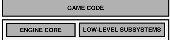
6.1 The game code 33
6.2 The engine code 34
6.3 Engine core 35
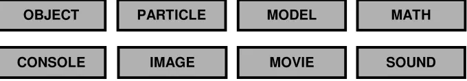
6.4 Low-level subsystems 37
7
Architecture Details ... 41
7.1 Code structure and conventions 41
7.2 Dynamic vs. static subsystem binding 43
7.3 Abstract rendering and shaders 45
7.4 Portability 46
7.5 Extensibility 48
8
Low-level Subsystem Specifications ... 50
8.1 Host system encapsulation 50
8.2 Graphics API encapsulation 55
9
Managing Objects ... 58
9.1 Object types and classes 58
9.2 The world 59
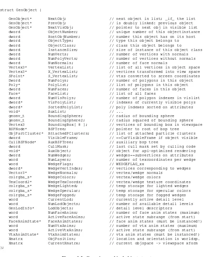
9.3 Generic graphical object 60
9.4 Object API 65
10
The ITER Interface ... 70
10.1 Specifying how primitives should be rendered 70
10.2 ITER rendering primitives 80
10.3 ITER rendering functions 87
11
Shaders ... 90
11.1 Components of a shader 92
11.2 Shader definition 92
11.3 Shader implementation 94
11.4 Color animations 94
11.5 Texture animations 96
11.6 Attaching a shader 98
11.7 The art of writing a shader 99
12
The Particle System ... 100
12.1 Basic definition of a particle 101
12.2 Particle clusters 102
12.3 Particle appearance animation 103
12.4 Particle behavior animation 103
12.5 How the particle system uses particle clusters 107
12.6 Derived particle cluster types 108
12.7 Particle system API 111
13
Networking ... 121
13.1 Game-code interface 123
13.2 Parsec protocol layer 125
13.3 Packet API layer 126
14
The Command Console ... 127
14.1 User command registration 128
14.2 Console API 131
PART III: Conclusion
15
Concluding Remarks ... 136
Design and Architecture
of a Portable and Extensible
Multiplayer 3D Game Engine
by
Markus Hadwiger
I would like to dedicate this thesis and corresponding work to my parents,
Dr. Alois and Ingrid Hadwiger,
Abstract
This thesis is about the design and architecture of a 3D game engine – the technology behind
a computer game featuring three-dimensional graphics.
Over the last couple of years, the development of 3D computer games and graphics research
have come ever closer to each other and already merged in many respects. Game developers
are increasingly utilizing the scientific output of the research community, and graphics
researchers have discovered computer games to have become an important application area of
their scientific work.
As the technology employed by computer games becomes more and more involved, the
design and architecture of the underlying engines attains a crucial role. Increasingly,
extremely modular designs encapsulating system-dependencies are chosen in order to allow
for portability from one target platform to another. Extensibility has also become important,
since many game engines are used for more than one game. It also helps foster a community
of game players that develops extensions for their favorite game and keeps the game alive for
a much longer period of time.
The topic of this thesis is a particular game engine – the Parsec Engine –, focusing on
architectural and design aspects. This engine emphasizes and allows for portability by
employing a very modular architecture. It is also a multiplayer game engine, i.e., it contains a
powerful networking component through which multiple players can play together.
Extensibility is achieved in many respects, although the Parsec Engine is not a completely
general game engine aiming to be a framework for every kind of game imaginable, but rather
attempts to achieve high performance for a specific type of game. Since it has been developed
in close conjunction with an actual computer game – Parsec, a multiplayer 3D space combat
game – it favors outer space settings with spacecraft.
Kurzfassung
Diese Diplomarbeit handelt von Design und Architektur einer 3D Computerspiele-Engine –
jener Technologie, die hinter einem Computerspiel steht, das dreidimensionale Graphik
einsetzt.
In den letzten Jahren haben sich die Entwicklung von 3D Computerspielen und die
Computergraphik-Forschung immer mehr angenähert und sind in vielerlei Hinsicht bereits
verschmolzen. Spieleentwickler nutzen in zunehmendem Ausmaß die wissenschaftlichen
Resultate der Forschergemeinschaft, und auch die Forscher in der Computergraphik haben
entdeckt, daß Computerspiele mittlerweile ein wichtiges Anwendungsgebiet ihrer Arbeit
geworden sind.
Da die Technologie die in Computerspielen eingesetzt wird immer komplexer wird, kommt
dem Design und der Architektur der zugrundeliegenden Engines eine immer bedeutendere
Rolle zu. Zusehends werden extrem modulare Designs gewählt, die Abhängigkeiten vom
eigentlichen Computersystem kapseln und so Portierbarkeit von einer Zielplattform zu einer
anderen ermöglichen. Erweiterbarkeit ist ebenso wichtig geworden, da viele Spiele-Engines
für mehr als nur ein Spiel eingesetzt werden. Diese Eigenschaft hilft ebenso beim Aufbau von
Spielergemeinschaften, in denen Spieler Erweiterungen für ihr Lieblingsspiel entwickeln und
es so für einen wesentlich längeren Zeitraum am Leben erhalten.
Das Thema dieser Diplomarbeit ist eine ganz bestimmte Spiele-Engine, die „Parsec Engine“,
wobei sie sich auf Architektur und Design konzentriert. Diese Engine betont und erlaubt
Portabilität, indem sie eine sehr modulare Architektur einsetzt. Weiters handelt es sich um
eine Mehrspieler-Engine, d.h. sie enthält eine leistungsfähige Netzwerkkomponente, durch die
mehrere Spieler miteinander spielen können.
Erweiterbarkeit wurde in vielerlei Hinsicht erreicht, obwohl die Parsec Engine keine komplett
allgemeine Engine mit dem Ziel, für alle möglichen Arten von Spielen verwendbar zu sein,
ist, sondern versucht, hohe Leistung bei einem bestimmten Spieltyp zu erzielen. Da sie eng
zusammen mit
einem vollständigen Computerspiel entwickelt
wurde – Parsec, ein
Mehrspieler-3D-Weltraumkampf-Spiel – bevorzugt sie Weltraum-Szenen mit Raumschiffen.
Acknowledgments
I would like to express a very special thank you to my “coach”
Dieter Schmalstieg
for
supervising this thesis, supporting my vision and approach to it, many helpful comments and
remarks, and putting up with me as a student in general. And – I will not forget my promise of
an extended session of playing Parsec.
Since Parsec has become a real team effort over the years, I would like to express my thanks
and admiration to all the talented members of the Parsec team for their great work and
dedication:
Andreas Varga
,
Clemens Beer
, and
Michael Wögerbauer
, who are all great programmers and
have contributed a lot to the spirit of the Parsec project.
Alex Mastny
, who has truly astounded me with his ability to create ever more impressive
artwork and designs.
Stefan Poiss
, whose musical abilities are still a miracle to me after all those years, and the
resulting music always managed to cheer me up and motivate me.
Karin Baier
, for giving voice to an entire universe.
Thanks to
Thomas Bauer
for support in numerous and invaluable ways, and
Uli Haböck
for
many insightful discussions on mathematics late at night.
Thanks to
Thomas Theußl
for tolerating the presence of gametech-talking nerds invading his
office, occupying his machine, and for always being there to share a cup of hot chocolate.
Thanks to
Karin Kosina
for a fine sense of humor, her spirit, and her outstanding tastes in
music –
Kaos Keraunos Kybernetos!
Thanks to
Helwig Hauser
for prodding me to give numerous talks, CESCG, and the Computer
Graphics Group –
la tante est morte, vive la tante !
Thanks to
Gerd Hesina
for a lot of help on numerous occasions.
Thanks to
Anna Vilanova i Bartrolí
and
Zsolt Szalavári
for being a lot of fun.
Introduction 1
1 Introduction
1.1 3D Computer game engines and graphics research
About ten years ago computer graphics research and computer games development were two totally separate areas with not much common ground. Computer games have always been almost exclusively targeted at the consumer market, and the graphics capabilities of consumer hardware at that time were practically non-existent from the point of view of computer graphics researchers. Thus, researchers were using expensive high-end graphics workstations, and game developers were targeting entirely different platforms. This had the implication that algorithms and techniques developed and used by the computer graphics research community could not really be employed by game developers. Graphics researchers, on the other hand, also did not view computer games as an application area of their scientific work.
However, the last decade, and the last couple of years in particular, have seen low-cost consumer graphics hardware reach – and in many areas even surpass – the capabilities of extremely expensive high-end graphics hardware from just a short time ago. This has led to computer game developers increasingly utilizing the scientific output of the research community, with an ever diminishing delay between introduction of a new technique and its actual use in a consumer product. Computer games research and development has thus become a very important application area for graphics researchers.
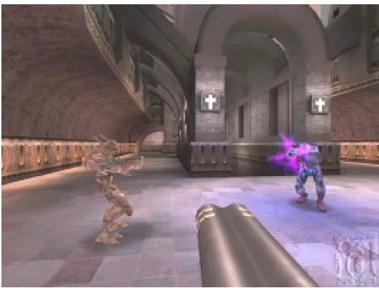
The game engines driving today’s 3D computer games are indeed an incredibly interesting venue where computer graphics research and engineering meet. However, although the graphics component of current game engines is probably the most visible one, a game engine is not only graphics. One could say that the term game engine subsumes all the technology behind a game, the framework which allows an actual game to be created, but viewed separately from the game’s content. This also includes networking, AI, scripting languages, sound, and other technologies.
Figure 1.1: Two highly successful game engines. Left: Quake. Right: Unreal
In addition to driving highly successful games in their own right, the most prominent game engines of the last several years, like the Quake [Quake] and Unreal [Unreal] engines, have been remarkable licensing successes. Although both were originally created for a particular game, these engines are ideal to be used for the creation of other games with entirely new content like game play, graphics, sound, and so forth. In fact, the effort necessary to create a top-notch game engine has become so tremendous, that it is also very sensible from a business point of view to make one’s engine available for licensing to other companies, allowing them to focus more on actual content creation than on the technology itself. This is even more important for companies that are simply not able to develop an entire engine and a game from scratch at the same time, than for the company allowing licensing of its engine.
Introduction 2 genre. On the other hand, this flexibility is also one of the major problems inherent in generic engines. Since they are not tightly focused on a rather narrowly defined type of game, they are not easily able to achieve the levels of performance of engines specifically tailored to a certain genre. Another problem of generic engines is that most game development houses prefer licensing an engine with already proven technology, i.e., a highly successful game that has sold at least on the order of one million units.
1.2 What this thesis is about
This thesis contains a lot of material pertaining to the architecture of computer game engines in general, but most of all it is about the design and architecture of a specific engine. This engine – the Parsec engine – is a highly portable and extensible multiplayer game engine. The design of this engine was guided by certain key design criteria like modularity, flexibility, extensibility, and – most of all – portability.
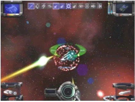
As opposed to generic game engines, the Parsec engine belongs to the class of game or genre-bound engines. This is also to say that it has been developed in parallel with an actual computer game, not coincidentally called Parsec – there is no safe distance [Parsec].
Figure 1.2: Parsec – there is no safe distance
Parsec is a multiplayer 3D space combat game, specifically targeted at Internet game play. Basically, players can join game play sessions in solar systems, and also jump from solar system to solar system using so-called stargates, interconnecting them. The emphasis is on fast-paced action, spectacular graphics, and background sound and music supporting the mood of the vast outer space setting. Chapter 5 contains a detailed overview of the game and its underlying concepts.
The Parsec engine offers high performance graphics utilizing an abstract rendering API, and a modular subsystem architecture encapsulating system-dependencies in order to achieve high portability. The networking subsystem is also independent from the underlying host system and transport protocol used. The current implementation supports Win32, Linux, and the MacOS as host systems, OpenGL and Glide as graphics APIs, and TCP/IP and IPX as networking protocols. Since one of the major goals in the development of the Parsec engine was to achieve high portability, porting to additional host systems, graphics APIs, and networking protocols is a rather straightforward process.
Introduction 3
1.3 How this thesis is structured
This thesis consists of three major parts.
Part One – Foundations and Related Work – covers fundamental issues like some very important graphics algorithms used in many game engines. It also contains a short review and introduction to the most important low-level graphics APIs used in 3D computer games, like OpenGL and Glide. The related work aspect is most prevalent in an overview of the evolution of 3D computer games and consumer 3D hardware over the last decade. In this part we will cover a lot of background material about computer games and the algorithms and techniques they use or have used in the past.
Part Two – Design and Architecture of Parsec –covers the main topic of this thesis, the design and architecture of the Parsec engine. Although the focus is on architectural and design aspects, many implementation issues are covered in detail. The key design goal of portability is central to the entire architecture of the engine. We will first review the game Parsec, then give an overview of its architecture and continue with more details about the architecture and its implementation. After these more general parts we will be devoting a single chapter to each of the major engine components.
Part Three – Conclusion –concludes with a comprehensive bibliography and offers some concluding remarks.
1.4 Overview of implementation
The implementation of the work described in this thesis is Parsec, the Parsec engine, and the Parsec SDK (Software Development Kit).
Parsec is the space combat computer game employing the accordingly named engine in order to present an interactive gaming experience to the player.
The Parsec SDK is a subset of the Parsec engine and game code, which will be made available on the Internet in source code form, in order to allow development of user modifications and additions, like new weapons and special effects, modes of game play, or even total conversions, i.e., an almost entirely different game.
This thesis is also intended for providing background and reference information to developers intending to work with the Parsec SDK.
The implementation of all of these components currently consists of about 180,000 lines of code, written in a C-like subset of C++, contained in about 900 source files, which amount to about 7MB of code. Supported host systems are Win32, MacOS, and Linux. Both OpenGL and Glide (3dfx) are supported as target graphics APIs on all of these host systems. The available implementations of the networking component support the TCP/IP suite of protocols and Novell’s IPX.
The code is very modular, especially with respect to portability between different host systems and graphics APIs. It transparently supports both little-endian (e.g., Intel x86) and big-endian (e.g., PowerPC) systems, and encapsulates many other details differing between target platforms.
It is contained in a hierarchically structured source tree, whose layout corresponds to the subsystem architecture, and host system and graphics API targets, as will be described in the main part of the thesis (Part Two). Since the system-dependent parts are cleanly separated and isolated, it is easily possible to extract only those source files needed for a specific target platform and/or graphics API.
PART I:
Algorithms 5
2 Algorithms
This chapter covers some fundamental algorithms that can be found in almost every 3D game engine, most of all focusing on occlusion culling algorithms and hierarchical subdivision.
Although the visibility determination problem at the lowest level is nowadays easily solved with hardware z-buffering in most systems, even the fastest hardware available cannot handle entire scenes consisting of, for example, a million polygons at interactive rates. So, the naive approach of simply throwing all polygons in a scene at the hardware just won’t work. It is not sufficient to employ visibility algorithms that need to check every single primitive in the scene to resolve visibility. Overall scene complexity ought to have no significant impact on the processing time for a single generated image. Rather, this processing time should depend solely on the complexity of the part of the scene being actually visible. Algorithms with this property are calledocclusion culling algorithmsoroutput sensitive visibility algorithms[Sud96].
In this overview, the distinction between objects and polygons in a scene is somewhat put aside, as we often assume objects to consist of polygons and consider objects at either the object level or the polygon level, as appropriate. Despite the emphasis on polygonal scenes, since they are simply the most important ones in interactive systems, some of the concepts and algorithms we discuss are also applicable to other object representations−e.g., implicit surfaces, constructive solid geometry (CSG), or objects modeled as collection of spline surface patches−if only objects’ bounding volumes are considered.
Nevertheless, the most advanced and also most recent work mostly considers purely polygonal scenes. Of course, all algorithms are trivially applicable if a non-polygonal scene is converted to an explicit polygonal representation in a preprocessing step. Hence, we do not explicitly consider non-polygonal scene or object representations in our discussion.
There are two large steps which need to be taken in order to prune a given scene to a manageable level of complexity:
The first step is to cull everything not intersecting the viewing frustum at all. Since that part of the scene cannot contribute to the generated image in any way it should be eliminated from processing by the graphics pipeline as early as possible. Additionally, those parts of the scene have to be culled in large chunks, because we do not want to clip everything and conclude that nothing at all is visible afterwards. Thus, there has to be some scheme to group polygons and objects together, ideally in a hierarchical fashion.
The second step, which needs to be taken after all polygons outside the viewing frustum have already been culled, is the elimination of unnecessary overdraw. Especially in complex, heavily occluded scenes1the number of polygons contained in the viewing frustum will still be too high to be handled by z-buffering alone. Everything still present at this step is potentially visible, but only with respect to the entire viewing frustum. A large number of polygons, depending on the scene, will be drawn into the frame buffer only to be overdrawn by polygons being nearer to the viewpoint later on. And, depending on drawing order, a large number of polygons will be rasterized by the hardware only to be separately rejected at every single pixel as being invisible, because a nearer polygon has already been drawn earlier on and filled the z-buffer accordingly. So, if those polygons could be identified before they are submitted to the hardware, a huge gain in performance would be possible, again, depending on the scene. In heavily occluded scenes the speedup gained can be enormous. Naturally, the efficiency of this identification process is an important economical factor.
To summarize, polygons have to be culled in essentially two steps. First, everything not even partially contained in the viewing frustum is identified and culled. Second, everything that is entirely occluded by other objects or polygons is culled. The remaining polygons can be submitted to the hardware z-buffer to resolve the visibility problem at the pixel level, or any other algorithm capable of determining exact visibility can be used. Alternatives to z-buffering for resolving exact visibility are mostly important in software-only rendering systems, though.
1
Algorithms 6
2.1 Hierarchical Subdivision
An important scheme employed by virtually every occlusion culling algorithm is hierarchical partitioning of space. If a partition high up in such a spatial hierarchy can be classified as being wholly invisible, the hierarchy need not be descended any further at that point and therefore anything subdividing that particular partition to a finer level need not be checked at all. If a significant part of a scene can be culled at coarse levels of subdivision, the number of primitives needing to be clipped against the viewing frustum can be greatly reduced.
Hierarchical subdivision is the most important approach to exploiting spatial coherence in a synthetic scene.
We are now going to look at some of the most common spatial partitioning schemes employing some sort of hierarchy and their corresponding data structures.
Hierarchical Bounding Boxes
A simple scheme to impose some sort of hierarchy onto a scene is to first construct a bounding box for each object and then successively merge nearby bounding boxes into bigger ones until the entire scene is contained in a single huge bounding box. This yields a tree of ever smaller bounding boxes which can be used to discard many invisible objects at once, provided their encompassing bounding box is not visible [Möl99].
However, this simple approach is not very structured and systematic and therefore useful heuristics as to which bounding boxes to merge at each level are difficult to develop. The resulting hierarchy also tends to perform well for certain viewpoints and extremely bad for other locations of a synthetic observer.
To summarize, the achievable speedup for rendering complex scenes by using such a scheme alone for occlusion culling is highly dependent on the given scene and, worse, on the actual viewpoint, generally rather unpredictable and therefore simple hierarchical bounding boxes are very often not sufficient as sole approach to occlusion culling, especially if observer motion is desired. That said, some variant of this idea can nevertheless be very useful when used to provide auxiliary information or setup data.
Octrees
The octree is a well known spatial data structure that can be used to represent a hierarchical subdivision of three-dimensional space. At the highest level, a single cube represents the entire space of interest. A cube for which a certain subdivision criterion is not yet reached is further subdivided into eight equal-sized cubes−their parent cube’s octants. This process can be naturally represented by a recursive data structure commonly called octree. Each node of an octree has from one to eight children if it is an internal node; otherwise it is a leaf node.
In the context of occlusion culling, octrees are usually used to hierarchically partition object or world space, respectively. For example, each object could be associated with the smallest fully enclosing octree node. Culling against the viewing frustum can then be done by intersecting frustum and octree, culling everything contained in non-intersecting nodes. This intersection operation can also easily exploit the hierarchy inherent in the octree. First, the root node is checked for intersection. If it intersects the viewing frustum, its children are checked and this process is repeated recursively for each node. A node not intersecting the viewing frustum at all can be culled together with its entire suboctree.
This scheme can also be employed to cull entire suboctrees occluded by other objects, provided such an occlusion check for octree cubes is possible and can be done effectively.
Algorithms 7 The two-dimensional version of an octree is called quadtree and can be used to hierarchically subdivide image space, for instance. Incidentally, image space pyramids and image space quadtrees, although very similar, are not the same. A pyramid always subdivides to the same resolution in all paths, i.e. it cannot adapt to different input data as easily; in particular, it is not possible to use different resolutions for different areas of an image.
For an in-depth explanation of octrees and quadtrees, their properties and corresponding algorithms, as well as detailed descriptions of other hierarchical data structures, see [Sam90a] and [Sam90b].
K-D Trees
K-D trees [Ben75] can generally be used to hierarchically subdivide n-dimensional space. A k-D tree is a binary tree, partitioning space into two halfspaces at each level. Subdivision is always done axial, but it is not necessary to subdivide into two equal-sized partitions. So, − in contrast to octrees, where subdivision at each level is always regular − the selection of a separating hyperplane can depend more on the actual data. Usually one halfspace contains the same number of objects as the other halfspace, or exactly one more. This also ensures that the corresponding binary tree is balanced. Additionally, subdivision is not only axial, but also progresses in a fixed order. First, space is subdivided along the first dimension, then the second, and so on, until all k dimensions have been used up. Then the subdivision proceeds using the first dimension once again, as long as a certain termination criterion for further partitioning has not yet been reached.
K-D trees have a number of applications−e.g., n-dimensional range queries; see [Ber97], for instance−, but the most important areas of application as pertaining to occlusion culling are three dimensional k-D trees to hierarchically group objects in object and world space, respectively, and two dimensional k-D trees for image space subdivision.
BSP Trees
Binary Space Partitioning or BSP trees, as detailed in [Fuc80], can be seen as a generalization of k-D trees. Space is subdivided along arbitrarily oriented hyperplanes (planes in 3-D, lines in 2-D, for instance) as long as a certain termination criterion is not yet reached. The recursive subdivision of space into two halfspaces at each step produces a binary tree where each node corresponds to the partitioning hyperplane. Normally, a scene consisting of polygons is subdivided along the planes of these polygons until every polygon is contained in its own node and the children of leaf nodes are empty halfspaces. Every time space is subdivided, polygons straddling the separating plane need to be split in two. The newly created halves are assigned to the positive and negative halfspaces, respectively. This leads to the problem that the construction of a BSP tree may introduce O(n2) new polygons into a scene, although this normally only occurs for extremely unfortunate subdivisions.
Primarily, a BSP tree is not used to merely partition space in a hierarchical fashion; it’s a very versatile data structure that can be used in a number of ways. The most important thereof is exact visibility determination for arbitrary viewpoints. For entirely static polygonal scenes a BSP tree can be precalculated once and its traversal at run time with respect to an arbitrary viewpoint yields a correct back-to-front or front-to-back drawing order in linear time.
At each node it must be determined if the viewpoint lies in the node’s positive or negative halfspace, respectively. If the viewpoint is contained in the node’s positive halfspace everything in the negative halfspace has to be drawn first. Then, polygons2attached to the node itself may be drawn. Last, everything in the positive halfspace is drawn. This process is repeated recursively for each node and yields a correct drawing order for all polygons contained in the tree.
An important observation to make is that each node implicitly defines a convex polytope, namely the intersection of all the halfspaces induced by those hyperplanes encountered when traversing the BSP tree down to the node of interest. This property is very useful with respect to the subdivision of space into convexcells, an operation often needed by occlusion culling algorithms. If you have, for instance, a polygonal architectural model, a BSP tree can be used to subdivide the entire model into a set of convex polytopes−the cells−which, in the 3-D case, are convex polyhedrons. For such an application it might be sensible to not attach single polygons to the BSP
2
Algorithms 8 tree’s nodes, but to only attach separating planes to internal nodes and entire convex cells together with their constituting polygons to leaf nodes. The model’s polygons would then be contained in the boundaries of those convex cells (their ‘walls’). Such a modified BSP tree approach yields explicitly described convex polytopes instead of their implicit counterparts in an ordinary BSP tree.
During the walkthrough phase, a BSP tree may be used to easily locate the convex cell containing the synthetic observer, cull entire subtrees against the viewing frustum, and obtain a correct drawing order for whole cells [Nay97]. The walls of those cells themselves may be drawn in any order, since they correspond to the boundaries of convex polyhedrons and thus cannot obscure one another.
For purposes of occlusion culling it can be extremely useful to attach probably axial bounding boxes to each of the BSP tree’s nodes, encompassing all children of both subtrees and the node itself. During tree traversal each node’s bounding box is checked against the viewing frustum and−provided that no intersection is detected−the entire subtree can be culled.
Also, BSP trees can be effectively combined with the notion of potentially visible sets, see below, to obtain a correct drawing order for the set of potentially visible cells.
2.2 Occlusion Culling
This section reviews several key ideas and data structures used in occlusion culling.
Potentially Visible Sets
Many occlusion culling algorithms use the notion of potentially visible sets (PVS), first mentioned by [Air90]. This term denotes the set of polygons or cells in a scene which is potentially visible to a synthetic observer. A polygon or cell contained in the PVS is only potentially visible, which is to say it is not entirely sure that it really can be seen from the exact viewpoint at any specific instant. The reason for this is that most algorithms trade the exact determination of visibility for improvements in computation time and an overall reduction of complexity of the algorithm. The result of a visibility query is not the exact set of visible polygons or cells, but a reasonably tight conservative3estimate. For instance, in approaches that precalculate potentially visible sets for each cell of a scene subdivided into convex cells, the viewing frustum cannot be taken into account, since the orientation of the observer at run time is not known beforehand. But, the set of all polygons that can be seen from any viewpoint with any orientation in the convex cell is a conservative estimate for the actual set of visible polygons once the exact position and orientation of the observer are known. Moreover, due to algorithm complexity and processing time considerations, maybe not even the former set is calculated exactly but rather estimated in a conservative manner.
If, as mentioned before, cell-to-cell visibility information is precomputed and attached to each cell, it can be retrieved at run time very quickly to establish a first conservatively estimated PVS. This PVS can subsequently be further pruned by using the then known exact location and orientation of the synthetic observer in a specific cell [Tel91, Tel92b]. This can be done by simply culling the PVS against the actual viewing frustum, for example.
Portals
Intuitively, a portal [Lue95] is a non-opaque part of a cell’s boundary, e.g. a section of a wall where one can see through to the neighboring cell. If the entire scene is subdivided into cells, the only possibility for a sightline to exist between two arbitrary cells is the existence of a portal sequence that can be stabbed with a single line segment. So, if a synthetic observer in cell A is able to see anything in cell B there must exist a sequence of portals Piwhere a single line pierces all of these portals to connect a point in A with a point in B.
Rephrased, if we want to determine if anything located in a given cell (including the cell’s walls) is visible, through any portals, from the cell the current viewpoint is contained in, we need to calculate if such a sightline exists [Fun96].
3
Algorithms 9 Another way to tackle the concept of portals is to imagine a portal as an area light source where one wants to determine if any of the portal’s emitted light is able to reach any point in a given cell. If this is the case, a sightline between those two portals exists and therefore an observer in cell A is possibly able to see some part or all of cell B [Tel92a].
One use of portals is the offline determination of the PVS for a given cell, namely the set of all cells for which a stabbing sequence from a portal of the source cell to a portal of the destination cell exists, regardless of the exact location of the viewpoint within the source cell. This information can be precomputed for each cell in a model and used at run time to instantly retrieve a PVS for any cell of interest.
Alternatively, the concept of portals can be used to dynamically determine a PVS for any given cell entirely at run time, without the use of any precomputed information. The next section conceptually compares both of these approaches.
Static vs. Dynamic Visibility Queries
A very important property of an algorithm dealing with the determination of potentially visible sets is its ability or inability to handle dynamic changes in a scene efficiently. This depends on whether the algorithm computes the PVS offline or dynamically at run time.
If dynamic scene changes need to be accommodated quickly−i.e., without a lengthy preprocessing step−the algorithm has to support dynamic visibility queries.
Naturally, dynamic visibility queries suffer from a performance penalty as opposed to static visibility queries.
First, PVS information cannot simply be retrieved from a precomputed table but has to be computed on the fly. To alleviate this problem some algorithms try to exploit temporal coherence (see next section).
Second, due to processing time constraints, the PVS generated by dynamic visibility queries may be not as tight as the PVS generated by table lookups and pruned to the viewing frustum at run time. This incurs a performance penalty at the rasterization level, as the low level visibility determination−in most cases a z-buffer−has to deal with additional invisible polygons.
One promising approach employed by more recent algorithms is to combine both static and dynamic information to determine a PVS. Some amount of a priori information is precomputed and used to speed dynamic visibility queries and enhance their effectiveness, respectively.
Spatial and Temporal Coherence
In the attempt to make occlusion culling algorithms more effective, it is important to take advantage of any potential coherence as much as possible.
The term spatial coherence subsumes both object space and image space coherence. Object space coherence describes the fact that nearby objects and polygons in object space very often belong to the same ‘class’, say, with respect to their visibility. A hierarchical subdivision of object space can directly take advantage of this coherence. The hierarchy is used to ensure that nearby objects are considered together first − to be only considered at a finer level if their invisibility cannot be proved at the coarser level.
Image space coherenceis the analog to object space coherence in the two dimensional, already projected, image of a scene. It can be exploited by a subdivision of image space using, e.g., an image space BSP tree. Alternatively, coherence at the pixel level might also be used to advantage by, say, using the fact that adjacent z-buffer entries normally do not have greatly differing depth values.
High-performance Low-level Graphics APIs 10
3 High-performance Low-level Graphics APIs
Over the last few years, the focus of graphics development in the area of entertainment software has clearly shifted from exclusive software rendering to the support of consumer-level 3D hardware accelerators. Very prominent examples of such accelerators are boards featuring a chipset of the Voodoo Graphics family by 3dfx Interactive. Although powerful graphics boards are already widespread throughout the potential customer base for computer games, most companies still offer optional software rendering in their products. The most important reason for this is that the majority of desktop computers is still not equipped with special-purpose 3D hardware. Nevertheless, this situation is changing rapidly and many future releases will require hardware acceleration.
A very important issue in the development of contemporary computer games is the choice of the underlying graphics API that is used to access the facilities offered by the graphics hardware. One criterion for this decision is whether to support only a single family of accelerators through a proprietary API like 3dfx’s Glide, or a multitude of different hardware vendors’ products through an industry-standard API like OpenGL or Direct3D. From a marketing point of view, this decision might seem to be easy. Clearly, the bigger the customer base, the better. A very important issue, however, is support and quality of an API−in particular, the availability and quality of the drivers necessary to access the target hardware. The choice of API has always been far from clear-cut and is still crucial. For this reason, many developers adopt the approach of supporting more than one API, letting the user select at installation or startup time, maybe even on-the-fly from within the program.
If one decides to support more than one graphics API, maybe in addition to proprietary software rendering, the issue of how to effectively develop in such a scenario becomes critically important. Since the Parsec engine supports OpenGL and Glide transparently, this issue is of special interest in the context of this thesis.
In order to support several graphics APIs in the Parsec engine, we have designed an abstract interface layer comprised of several subsystems. This abstract interface is implemented for all supported APIs. However, all other graphics code resides entirely above this interface layer and is therefore independent from the graphics API actually used at any one time. Supporting additional graphics APIs is possible by simply implementing the functionality required by the interface for the new target. Thus, the vast majority of the code does not need to be changed.
This chapter briefly reviews some issues regarding the most important graphics APIs in the current desktop consumer-market.
3.1 Glide
Glide [Glide] is the low-level, hardware-oriented graphics API introduced by 3dfx Interactive along with its first Voodoo Graphics accelerator in 1996. It is a proprietary API, so it is only supported by 3dfx’s hardware. In 1996, however, these accelerators were the de-facto standard, so Glide has been used as primary or at least alternative graphics API by many computer games for several years.
Glide has several key advantages, foremost of all its high performance and ease of use. In fact, the API is so hardware-oriented that it practically does not support anything the hardware itself does not support. So, since Voodoo Graphics accelerators are basically fast rasterizers, i.e. operating in two-dimensional screen space and rasterizing polygons already transformed, lit, clipped, and projected by the application, Glide is also only a rasterization API. It does not perform any clipping, 3D transformations, and other operations at a higher level than pure graphics primitive rasterization. Texture memory management is also the sole responsibility of the application programmer. Of course, all this means a lot more work for the programmer, but also a lot more flexibility, like all trade-offs between high-level and low-level programming.
In addition to being very high performance, Glide is also very ease to use. It offers an easy to understand C application programming interface, and – definitely a crucial factor for its tremendous success with game developers – a very good SDK containing all necessary documentation that is available for free to anyone interested. There is no special registration or fee necessary to get at the SDK, 3dfx made it freely available for download almost right from the beginning [Glide].
High-performance Low-level Graphics APIs 11 hardware accelerator platform, and Glide was the prevalent high-performance, low-level, consumer 3D graphics API.
However, starting with NVIDIA’s Riva TNT in 1998, many new low-cost graphics accelerators offering very high performance have become available, and the driver situation has also improved tremendously. Thus, a migration from using Glide to APIs like OpenGL or Direct3D, that support a multitude of different hardware accelerators, can be observed.
3.2 OpenGL
OpenGL [Seg98] is a very powerful and widely used graphics API that evolved from Silicon Graphics’ IrisGL. Originally meant for programming workstation-class 3-D hardware, high-quality OpenGL drivers are available for the most important consumer products of today. This is also due to the fact that workstation and consumer hardware are in the process of converging in many respects. A very important property of OpenGL is that it is supported on many platforms. Graphics code written for OpenGL can easily be ported to a PC, a Macintosh, and
− of course− an SGI workstation, among others. OpenGL offers an easy to use C application programming interface, and is also an extremely well documented API.
For more information about OpenGL see [Seg98, Woo99, OGL]. The SIGGRAPH course on advanced graphics programming techniques using OpenGL [McR00], that has been held over several consecutive years, also offers a wealth of information on OpenGL and graphics programming on contemporary graphics hardware in general.
3.3 Direct3D
Direct3D, which is part of [DirectX], also supports a multitude of graphics hardware, although it is exclusively restricted to Microsoft Windows platforms. Nevertheless, these comprise the most important segment of the computer games market for the desktop, and Direct3D is widely supported by game developers.
A very important difference between OpenGL and Direct3D is that an OpenGL implementation is required to support the entire feature set as defined by the standard, whereas Direct3D exports the functionality of the hardware in the form of capability bits. This implies that OpenGL must emulate missing hardware functionality in software. With Direct3D, the programmer has to explicitly determine what to do should desired features be found missing.
3.4 Geometry Processing
A crucial issue is whether an API supports geometry processing, or is rasterization-only. Since Glide exports only the features of the actual hardware and all Voodoo Graphics accelerators to date do not support geometry acceleration, the API does not support three-dimensional operations like transformation, clipping, and projection. All coordinates in Glide are screen-coordinates together with additional attributes that the hardware interpolates over a triangle, e.g., texture coordinates (U,V,W) and color (R,G,B,A). That is, coordinates are already in post-perspective space. As soon as accelerators supporting geometry processing in hardware become widespread, this poses a problem to the API. There are already two major versions of Glide − 2.x and 3.x, the latter already supporting a homogeneous clipping space−, and the API will probably continue to evolve with the capabilities of 3dfx hardware.
High-performance Low-level Graphics APIs 12 justified. The most important reason, however, to use the geometry support of a graphics API is to be prepared for the future widespread availability of hardware with dedicated geometry processing support.
Game Technology Evolution 13
4 Game Technology Evolution
This chapter provides an overview of the technology employed in 3D computer games over the last decade. Technology in this context means both software technology, e.g., the algorithms and techniques employed, as well as hardware technology, which has become important with the advent of powerful low-cost consumer graphics hardware in 1996.
Section 4.1 covers seminal computer games, and section 4.2 is devoted to 3D hardware accelerators.
4.1 Seminal 3D Computer Games
In this section, we illustrate the evolution of 3D computer games over the last eight years by looking at several seminal games of that period. Prior to 1992, computer games were either not three-dimensional at all, or used simple wireframe rendering, or maybe flat-shaded polygons. In some cases, 3D information was pre-rendered or drawn into bitmaps, and used at run-time to produce a three-dimensional impression, although there was no actual 3D rendering code used in the game itself.
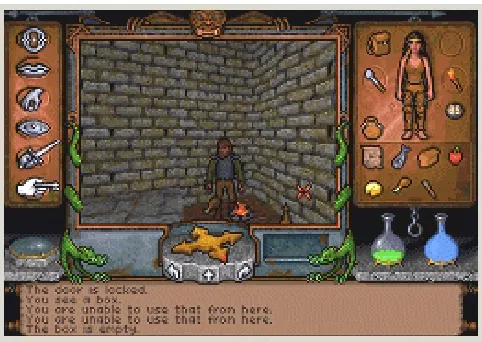
Ultima Underworld (Looking Glass Technologies, 1992)
In Ultima Underworld, a role-playing game set in the famous Ultima universe created by Origin Systems, players were able to walk around in a fully texture-mapped [Hec89, Hec91] 3D world for the very first time. Most role-playing games prior to Ultima Underworld were not three-dimensional at all, e.g., using a top-down or isometric perspective and tile-based 2D graphics like the earlier Ultima games. One could not walk around in these worlds in the first-person perspective, so the feeling of “actually being there” was rather limited.
Another earlier approach was to combine hand-drawn graphics tiles with a very restricted first-person view, which was originally made popular in the 1980s by the game Dungeon Master, by FTL. However, the world in Dungeon Master was not actually 3D; player positions were constrained to a predefined grid and the only allowed rotation of the view was in steps of 90 degree angles, so one could only look straight ahead, straight to the left or right, or to the back. This approach creates a limited three-dimensional impression without using any actual 3D calculations at run-time.
The world in Ultima Underworld, however, contained basically no technological viewpoint restrictions and was – at least to a certain extent – fully 3D. The player position was not constrained to a simple grid anymore, players were able to seamlessly walk over actual texture-mapped floor polygons. Rotations about the principal axes were also allowed, most notably looking to the left or right with arbitrary rotation angles, and looking up or down with proper perspective fore-shortening of polygons. This is especially remarkable since it wasn’t until several years later that most 3D games were using an actual rotation about the horizontal axis for this purpose, instead of not allowing the player to look up or down at all, or faking the rotation by using a shear transformation.
However, the flexibility allowed for by Ultima Underworld’s 3D engine had its price in terms of performance. Since the whole world was texture-mapped and polygons could be viewed at arbitrary oblique angles, the texture-mapper was simply not able to texture the entire screen in real-time, at least not on most consumer hardware available in 1992. For this reason, the game used a smaller window for rendering the 3D view of the world, and used the remaining area of the screen for user interface elements like icons, the player character’s inventory, an area for text output, and the like.
For a role-playing game like Ultima Underworld its rather slow speed was no problem, however, since it wasn’t a fast-paced action game after all, emphasizing game play and design much more than many 3D action games of the following years.
Game Technology Evolution 14 See figure 4.1 for a screenshot of Ultima Underworld.
Figure 4.1: Ultima Underworld (1992)
Wolfenstein 3D (id Software, 1992)
Shortly after Ultima Underworld, a small game developer named id Software released what would eventually found a new computer game genre: the first-person shooter, commonly abbreviated as FPS. This game, Wolfenstein 3D, emphasized fast-paced action above all, where the player was able to run around in first-person perspective with high frame rates, and the goal of the game was primarily to shoot everything in sight. However, this simple formula was easy to grasp and the fast action game play combined with equally fast frame rates contributed to a remarkable success.
The most important contribution of Wolfenstein 3D, however, was that it was to become the prototype for graphically and technologically much more sophisticated first-person shooters in the following years, like Doom and Quake. So, the questionable game content notwithstanding, Wolfenstein had a much higher impact on games in the following years in terms of technology than Ultima Underworld.
In contrast to Ultima Underworld, the game world in Wolfenstein was highly restricted. The player had only three degrees of freedom (DOF); two degrees for translation, and one degree for rotation. That is, movement was constrained to a single plane and the view point could only be rotated about the vertical axis. So, it was possible to look to the left and right with arbitrary viewing angles, but nothing else.
In order to avoid the negative performance impact of texturing the entire screen, only wall polygons were texture-mapped. The floors and ceilings were simply filled with a solid color.
See figure 4.2 for a screenshot of Wolfenstein 3D.
Game Technology Evolution 15 In addition to texturing only the walls, the placement of these walls was restricted in a way that all of them were placed in 90 degree angles to each other, and all walls were of the same height. This restriction of the world geometry, combined with the restriction on the allowed motion of the player, also made use of an extremely simplified texture-mapper possible. Walls could be rendered as a series of pixel columns, where the depth coordinate was constant for each column. So, the perspective correction had to be performed just once for each column, leading to an extremely optimized (and equally restricted) texture-mapper.
The visibility determination in a world like Wolfenstein’s also profited tremendously from the simplicity of the game world. The game used a simple ray-casting algorithm, where a single ray was cast to determine the entire visibility (and horizontal texture coordinate) of an entire screen column. Since all walls were of the same height, there was always exactly one wall visible per screen column, or none at all. Thus, as soon as the cast ray hit the nearest wall, the visibility determination for the corresponding column was done.
Similar to Ultima Underworld, all characters and objects in Wolfenstein 3D were two-dimensional sprites.
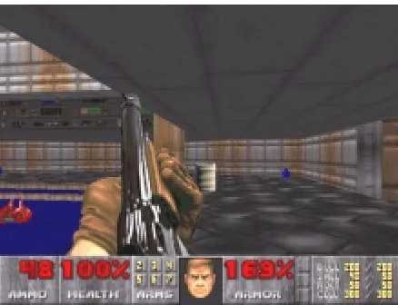
Doom (id Software, 1993)
When Doom first appeared in 1993, it managed to lift many of the restrictions that made its direct predecessor Wolfenstein 3D a very simple and tremendously restricted game. It is still one of the most successful computer games of all time.
Doom combined fast game play and high frame rates with a fully texture-mapped world like in Ultima Underworld, although the world geometry was still much more constrained. The basic premise was similar to Wolfenstein, but the complexity of Doom’s levels was truly remarkable for a game running on consumer hardware at the time.
Doom’s levels were represented as a single large 2D BSP tree, which was most of all used for visibility determination purposes. Levels could be constructed using some kind of two-dimensional floor plan, i.e., a top-down view, where each line segment corresponds to a wall and is displayed as a polygon in 3D by the game engine at run-time. Of course, this underlying 2D nature of Doom’s levels led to a lot of necessary restrictions like “no rooms above rooms,” where it was impossible to model multi-storied buildings or anything else where there are two floor or ceiling heights at the same position of a top-down view. Sometimes, such a combination of 2D geometry actually used to define some sort of restricted 3D geometry via lofting or extrusion is called 2.5D.
Doom was able to texture-map the entire screen at really high frame rates by once again cleverly exploiting the combination of a constrained world geometry with restrictions on the allowed rotation of the view point. Since all wall polygons were extruded orthogonally to the floor from the level representation at run-time, all visible polygons were either parallel to the floor plane, or orthogonal to it. Combined with the fact that view point rotation was only possible about the vertical axis, this yields the observation that the depth coordinate is always constant for an entire horizontal or vertical polygon span; for floor/ceiling and wall polygons, respectively. Sometimes, such an approach to texture-mapping is called “constant z texture-mapping.”
See figure 4.3 for a screenshot of Doom.
Game Technology Evolution 16 When using a BSP tree for visibility determination there are two basic approaches in which order the tree can be traversed in order to obtain correct visibility. The simplest is back-to-front rendering, in which the polygons are simply drawn from farthest to closest, in essence using a painter’s algorithm [Fol90]. Since the BSP tree yields a correct visibility order for an arbitrary viewpoint, it is easy to let nearer polygons overdraw polygons farther away and thus obtain a correct image.
The problem with back-to-front rendering, however, is that it draws a lot of unnecessary polygons, since it starts with the polygons that are most likely to not be visible at all. Most polygons of a level are invisible most of the time, because they are overdrawn by nearer polygons completely overlapping them.
A much better, but also more sophisticated, approach is to use front-to-back rendering instead. With this order of traversal, drawing starts with the nearest polygon and progresses to the farthest polygon. The major difference is that as soon as the entire screen has been filled by polygons drawn up to a certain position in the BSP tree, further traversal is completely unnecessary, since all visible polygons have already been drawn at that time.
Thus, Doom used front-to-back traversal of the 2D BSP tree representing the entire level, and kept track of covered pixel spans – which was necessary to prevent occluded parts of polygons farther away from overdrawing visible parts of polygons nearer to the view point – and stopped traversal as soon as it knew that the entire screen had been covered. This tracking of already covered screen areas/spans was much simpler in Doom’s 2.5D case than it would have been in the general 3D case.
Doom’s use of a BSP tree for level representation had the consequence that dynamically moving geometry was not really possible. Doors, for instance, were actually modeled as very small rooms, where the ceiling height was modified on-the-fly. It wouldn’t have been possible to model swinging doors, or the like. This was due to the fact that BSP trees are not really suited to handling dynamic geometry, especially not in real-time. Also, the building process of a BSP tree – the so-called BSP tree compilation – is very time-consuming, so there was a significant delay between designing a level and actually being able to try it out in the game.
Similarly to Ultima Underworld and Wolfenstein 3D, Doom still used simple sprites for characters and objects.
Another important aspect of Doom, albeit not graphics-related, was that it supported Novell’s IPX protocol for network game play on local area networks. Thus, it became the first multiplayer game with sophisticated 3D graphics that was played by a staggering number of people all over the world.
Another trend that started with Doom and had an extremely wide impact on computer games being developed after it, was that it was also highly user-extensible. Players could easily substitute graphics, sound effects, and the like, and even create their own levels with a wide variety of level editors that were developed by community members and made available for free in most cases. Today, many games come with a level editor out of the box and a thriving community is working on new content, as well as game modifications using source code released by the game developers themselves.
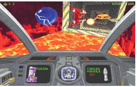
Descent (Parallax Software, 1994)
In 1994, a previously unknown company called Parallax Software released a game that featured a fully 3D, 360-degree, six degrees of freedom action game – Descent.
Descent was the first computer game that was able to render arbitrarily oriented polygons with perspective correct texture mapping at frame rates high enough for an action game. Most astoundingly, Descent featured a true three-dimensional world where the player could navigate a small spaceship through texture-mapped underground mines. It was a first-person game, but the fact that the player was controlling a spacecraft, instead of a character walking on foot, allowed all axes to be basically equal.
Game Technology Evolution 17 See figure 4.4 for a screenshot of Descent.
Figure 4.4: Descent (1994)
In order for a cell structure connected via portals to be traversed effectively, some kind of adjacency graph is usually used. Each node in the graph corresponds to a cell of the subdivision, and each edge describes a connection between two adjacent portals. Using this information it is very easy to start in a specific cell and jump from cell to cell by passing through interconnecting portals.
In such a system, traversal starts with the cell that contains the view point and some kind of depth-first algorithm is employed to recursively render the entire world. After rendering all solid walls of the cell containing the view point, all portals of this cell are touched and for each one of them everything is rendered that is visible through that particular portal.
Cells as building blocks of a world can also be used to store additional attributes, like lighting information, or whether that area (volume) is poisonous, has different gravity, etc. In Descent, the level designers could assign an ambient light intensity for each of the eight cell vertices. At run-time, vertices could be lit dynamically by moving light-sources like lasers, and the like, combining the dynamic lighting value with the static ambient light intensity on-the-fly. Lit polygons were rendered by applying Gouraud-shading [Rog98] to the textures of a cell’s walls.
One of the major properties of Descent’s world representation was that the cell subdivision was not built during a post-process after designing a level, as would be done in a BSP-based structure. Instead, the cell subdivision was an intrinsic part of the representation and the design process itself. The data structure used at run-time was basically constructed in its entirety while a level was being built. That is, since the level designers used the exact same geometric building blocks the engine itself used, and designated cell walls manually as either being solid (by assigning a texture), or being a portal (by not assigning a texture), no post-process subdivision and portal-extraction was necessary. The adjacency information of cells was also manually created while constructing a level, since new cells had to be explicitly attached to already existing cells when it should be possible to pass from one cell to another. There were also no problems with t-junctions [McR00], say, an edge of one cell touching a face of another cell in its middle. This was achieved by requiring that neighboring cells always share exactly four vertices, so the connection would be created from one face to another face, over the entire surface of each of these faces.
Many of these constraints on the design process could be viewed as a liability, but in the case of Descent it was very much tailored to the type of game. With such a “distorted-cube”-based approach to level-building it was actually very easy to build the interior of mines, mostly consisting of rather long tunnels with many twists and bends. All in all, Descent was a unique combination of game-design and technology, where each of these crucial parts was ideally tailored to its counterpart.
Game Technology Evolution 18 Descent used also many other clever restrictions in order to achieve its high performance. For example, all cell walls were textured using textures of a single size, namely 64x64. This allowed the use of texture-mapping routines hard-wired for this size, and made a lot of other administrational tasks with respect to textures easier. Texture-mapping was done using a linear interpolation of texture-coordinates for sub-spans of the horizontal spans of each polygon [Wol90], usually performing the perspective division only every 32 pixels. There were also a lot of highly specific assembly routines for texture-mapping, like one texture-mapper using a texture without any lighting, one for texture-mapping with lookup into a global ambient light or fading table, one for texturing and Gouraud-shading at the same time, and so on.
Descent still used fixed point and integer arithmetic for all of its geometrical computations like transformations, as did practically all of its predecessors.
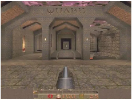
Quake (id Software, 1996)
Quake was the first first-person shooter that used true three-dimensional environments. It was also able to render geometry that was several orders of magnitude more complex than what Descent had been able to use. In order to achieve this, its developers had to use quite a lot of 3D graphics techniques that had previously never been used in a computer game.
See figure 4.5 for a screenshot of Quake.
Figure 4.5: Quake (1996)
The basic level structure in Quake used one huge 3D BSP tree representing the entire level. In some ways this could be viewed as being simply an extension from using a 2D BSP tree in Doom for 2.5D geometry, to using the 3D variant for arbitrary 3D geometry. In reality, however, 3D BSP trees are much more complicated to use for real-time rendering of complex environments than their 2D counterparts. This is true for many aspects of the transition from a rather restricted 2D-like environment to full 3D.
First, all polygons can basically be oriented arbitrarily, which mandates a texture-mapper that is able to map such polygons in real-time. Quake achieved this by performing the necessary perspective division only every 16 pixels and linearly interpolating in between. The difference between this approximation and the true perspective hyperbola was virtually not noticeable, since the length of these subspans was chosen accordingly.
Game Technology Evolution 19 There are two things to keep in mind with respect to this and the primary target platform of Quake, the Intel Pentium processor. First, conversion from floating point to integer (or fixed point) values, was always (and still is) an inherently slow operation. Thus, actual pixel arithmetic was always faster using integers, even if the performance of the Pentium processor’s FPU was comparable or faster than integer operations. After all, in order for a frame buffer or texture to be accessed one always needs integer coordinates (offsets). Second, there was a very specific reason for this exact point of transition from floating point to integer arithmetic. The Pentium processor was able to interleave floating point and integer operations, since its FPU and integer unit are separate and able to operate in parallel. Actually, Quake’s texture-mapper was able to interleave the perspective division with the interpolation and rendering of the actual pixels for a 16-pixel subspan, getting the much-feared division essentially for free.
Second, although a 3D BSP tree yields a correct visibility order for polygons, there are a lot of polygons that are contained in the view frustum but still not visible, because they are occluded by nearer polygons. A very powerful solution to this problem is the notion of potentially visible sets (PVS). With potentially visible sets, for each cell in the world (each leaf of the BSP tree), a set of other – potentially visible – cells is computed in a preprocess and stored along with the level data. At run-time, the set of potentially visible cells is retrieved for the cell containing the viewpoint and only polygons belonging to those cells are even considered for rendering. The PVS information is a so-called conservative estimate for visibility. That is, polygons not actually visible may be contained in such a set, but at least all visible polygons are required to be contained. Naturally, the tighter the visibility estimate is, the fewer unnecessary polygons will be rendered at run-time.
Another challenging problem with using a 3D BSP tree is how to render dynamically moving objects. The tree can be used to obtain a correct visibility order for the static world polygons, but polygons that are not part of the tree structure cannot be handled easily. One approach is to clip dynamic polygons into the leafs (convex cells) of the BSP tree, rendering them when the cell is rendered. This is a rather time-consuming process, however. Therefore, Quake uses a different approach to handle dynamically moving objects, like enemy characters.
Before we discuss how moving objects are handled in Quake, it is important to realize that standard z-buffering was basically never used for visibility determination in fast, software-rendered computer games. All the more complicated approaches like using BSP trees, portals, and the like, are – apart from other very important uses like collision detection, and higher level occlusion culling – in a way a faster but more complicated approach to visibility determination than the simple z-buffer approach. However, z-buffering with the necessary comparison per pixel, interpolation of z values, conditional stores into the z-buffer, etc. was in almost all cases too slow to be used in software rendering. (Note that this changed significantly with the introduction of hardware accelerators, which made the use of simple z-buffering for visibility detection at the pixel level feasible for the first time.)
Quake, however, used a clever variant of z-buffering to combine moving objects with the BSP-rendered world. While rendering the static world, filling the entire screen, a z-buffer was filled at the same time. From a performance point of view this is vastly different from a full buffering approach, since each entry in the z-buffer gets written exactly once, and there are no z value comparisons and z-z-buffer reads necessary. This is possible since the depth information is not used for rendering the world. After the entire screen has been filled with world polygons, the z-buffer contains a valid z-footprint for the entire scene. The relatively small number of pixels of moving objects’ polygons can then be rendered using standard z-buffering.
Quake also introduced an entirely new approach to lighting a level, using so-called light maps. Static lighting information was precomputed for patches covering all polygons of the level and stored in special texture maps, at a much lower resolution than the texture maps themselves, say, a light map texel every 32 texture map texels. In the original Quake simple light casting was used for calculating light maps, however, a full radiosity [Ash94] preprocess was employed later on.
In every computer game another important aspect is the approach to building a level. As has also become apparent in the section on Descent, level construction and representation is a very important aspect of every rendering engine. Quake introduced the CSG (constructive solid geometry) modeling paradigm to computer games. When building a Quake level, the designer is always using solid building blocks and combining them with the already constructed part of the level via boolean set operations (like in CSG trees). This is a very powerful modeling paradigm, easy to use, and among other useful properties guarantees that the entire level will be solid in the end, since single polygons are never used during construction.
Game Technology Evolution 20
GLQuake (id Software, 1996)
Quake used a proprietary software-renderer that had been developed from scratch, like practically all computer games at that and earlier times. Quite soon after the original Quake had been released, however, id Software released a Quake executable that was able to take advantage of the hardware acceleration offered by boards using the Voodoo Graphics accelerator by 3dfx Interactive. To distinguish this version of Quake from the standard version it was called GLQuake, since it used the OpenGL API that had previously been almost exclusively used on expensive high-end graphics workstations.
The timing was almost perfect, and GLQuake together with Voodoo Graphics accelerators achieved the breakthrough for consumer hardware acceleration in 1996. Previous attempts of hardware accelerators to take a hold in the consumer marketplace failed, most of all due to mediocre performance and the lack of a killer application, i.e. a top-notch computer game. GLQuake, however, became that killer application. Software-rendered Quake had severe performance problems in resolutions significantly higher than 320x200, say, 640x480, on all but the fastest computers of its time. This was mostly a problem of the lowest level of the graphics pipeline, i.e. the rasterizer – turning polygons into actual pixels and mapping them with a texture. The Voodoo Graphics accelerator was perfect for this kind of work and relieved the host CPU of the burden of performing a perspective division for each pixel (or every n-th pixel) which was the most important factor preventing 3D computer games from going to resolutions of 640x480 and higher.
See figure 4.6 for a direct comparison of software-rendered Quake and hardware-rendered GLQuake, for the same frame rate.
Figure 4.6: Quake vs. GLQuake (1996)
In addition to taking over the main load of rasterization, the Voodoo Graphics accelerators were also able to use bilinear filtering instead of point-sampling textures, which led to a much higher image quality. MIP-mapping could also be performed in real-time for each pixel individually, instead of just choosing an approximately suitable MIP-map level for an entire polygon, as software-rendered Quake had done for performance reasons.
In contrast to software-rendered Quake where light maps were combined with the base texture maps before actually using them for texturing using a sophisticated surface caching system, GLQuake rendered the light maps directly as a second pass, using alpha-blending. If the hardware supported it (Voodoo 2, Riva TNT, ...) base textures and light maps could even be rendered in a single pass, using single-pass multi-texturing.
Quake 3 Arena (id Software, 1999)