This document contains domestic imagery, which has been included consistent with applicable laws, directives and policies. Handle in accordance with
SUPPORTING REMOTE SENSING RESEARCH WITH SMALL UNMANNED AERIAL
SYSTEMS
R. C. Anderson*, P. C. Shanks, L. A. Kritis, M. G. Trani
National Geospatial-Intelligence Agency (NGA)
[email protected], [email protected], [email protected], [email protected]
KEY WORDS: sUAS, remote sensing, autopilot, mission planner, ground control system, VisualSFM, PhotoScan, DEMs, orthomosaics
ABSTRACT:
We describe several remote sensing research projects supported with small Unmanned Aerial Systems (sUAS) operated by the NGA Basic and Applied Research Office. These sUAS collections provide data supporting Small Business Innovative Research (SBIR), NGA University Research Initiative (NURI), and Cooperative Research And Development Agreements (CRADA) efforts in addition to in-house research. Some preliminary results related to 3D electro-optical point clouds are presented, and some research goals discussed. Additional details related to the autonomous operational mode of both our multi-rotor and fixed wing small Unmanned Aerial System (sUAS) platforms are presented.
1. INTRODUCTION
The NGA Basic and Applied Research Office has been involved in a number of projects with several universities and companies to test various platforms and sensors with the aim of providing a low-cost, easy to use system in order to facilitate remote sensing research. In addition, the ability for fast photo collection and processing can generate quality products for other applications such as disaster response planning. Currently there are two active CRADAs. One is with St. Louis University (SLU) involving sensor integration to support sUAS and remote sensing research. SLU has graciously provided lab space for building and testing the systems along with technical expertise. The other is with Urban Robotics, Inc. that provides UAS support with novel approaches to 3-dimensional visualization and geopositioning. They will be exploring new methods of collecting and processing the sensor data to increase the development of 3D rendered maps from small Unmanned Aerial Vehicle (sUAV) imagery. Vision Systems, Inc. developed a 3-d uncertainty measure using error propagation under a SBIR for their voxel modeling algorithm to reconstruct a 3-d volumetric scene. A toolkit is under development and they have agreed to release some of its code to NGA. Ohio State University’s Satellite Positioning and Inertial Navigation (SPIN) laboratory is working on the efficient compression of LiDAR wave forms and using sUAS for LiDAR data collection. Finally, NGA is gathering the data provided by the universities and companies to apply to their own in-house research.
2. ORGANIZATIONAL DETAILS
2.1 sUAS Goals
The goal of the sUAS is to provide an inexpensive, safe, easy to use, repeatable method to place payloads in the sky for remote sensing purposes supporting the widest variety of collection modes. NGA has several sUAS platforms to meet requirements
for payload capacity and collection geometry. There are two basic types of aerial platforms, fixed wing and multi-rotor. The fixed wing allows greater payload capacity with superior endurance. The trade-off is that the aircraft is always in forward flight. Also, our fixed wing (2.7m x1.8m) Rascal aircraft needs a relatively long area for takeoff and landing. Multi-rotors, however, offer nearly unlimited number of possibilities for collection geometry at the sacrifice of payload capacity and mission endurance. The NGA current inventory of multi-rotors consists of quadcopters, hexacopters, and an octocopter. Generally, the greater amount of engines corresponds to increased payload capacity and stability. The quadcopter airframe design NGA uses is the Team Black Sheep (TBS) Discovery. The right configuration of multi-rotors can fly in 25 knot winds easily to complete mapping missions. Those types of wind conditions will easily ground a manual aircraft or fixed-wing sUAS.
2.1 Autopilot
2.2 Mission Planner
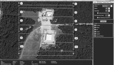
Useful photogrammetric and remote sensing tools are built into Mission Planner as well. Mission Planner has three basic collections modes: racetrack covers large areas with few turn-arounds, lawnmower collects over smaller areas using the same back and forth flight path as the racetrack, and circle with flights around a fixed area. Designing the typical lawnmower nadir collection mission consists of a few simple steps. First the user defines the target mapping region by drawing a polygon. With the polygon, a tool called Survey appears where the user can define altitude, camera parameters and cardinal headings (Figure 1). The proposed flight lines are calculated instantly showing the user important mission variables such as Ground Sample Distance, and anticipated mission duration. This lets the user know whether the area can be imaged on a single battery, or if multiple flights are required. Photogrammetric constraints such as focal length, overlap and sidelap can be factored into mission design too. Projected image footprints with overlap and sidelap are also available. After a few minutes, the mission is ready for upload to the sUAS.
Figure 1. Mission Planner survey tool plots flight lines base on mission constraints using ©2014 Google Earth image
Camera trigger options can be programmed from the autopilot via electrical impulse, IR strobe or mechanical servo. The autopilot will log the time, position and orientation of the camera, which is very useful for 3D reconstruction. Although NGA is using Alexmos 2 axis gimbal boards to help stablize the sensor payloads, it is envisioned that the Pixhawk autopilot will be able to drive the gimbal motors directly in near future firmware releases. Mission Planner works on a fixed wing plane, multirotor, helicopter, ground rover and even a boat. This substantially decreases the learning curve required to operate a variety of autonomously navigated vehicles. As part of the mission planning, a user can define predetermined landing zones called rally points. The autopilot will seek the closest point in the event of an emergency landing. If the sUAS is closest to the
The GCS also can be run from a smartphone and or tablet through several open-source apps (DroidPlanner v1, DroidPlanner v2, and Andropilot) which mirror the functionality of the laptop based Mission Planner. Utilizing the GPS on a smartphone or tablet,
Ardupilot is capable of a flight mode called “Follow Me” which literally follows the user around at a constant altitude. Combined with a realtime vehicle telemetry laced video feed beamed to the user, the situational awareness increases considerably. For multi-rotors, an extremely useful flight mode features the ability to circle around a Region of Interest (ROI) at a defined radius and altitude while the sUAS points at the center independent of its flight path. In summary, with the combination of sUAS and 3DRobotics’ autopilots, we can place and orient a sensor payload anywhere in 3D space.
2.3 Payloads
The TBS whose spider arm configuration eliminates rotor obstruction for our forward mounted GoPro payloads (approximately 400g including gimbal). Typical flight duration is about 15 minutes with a GoPro sized payload. The TBS Discovery is powered by a 5200mAH 4S Lithium-Polymer (Li-Po) battery pack. The TBS can fly approximately 5km downrange and land on a single battery charge. Should an emergency arise, such as loss of primary and secondary communications uplinks, battery failure, or GPS loss, the failsafe logic of the autopilot will safely return the sUAS and payload to the ground. By way of contrast, the modified Rascal with a gasoline engine has flight duration in excess of 3 hours with a payload as high as 11 kg. Using the same autopilot and mission planning tools. However, a runway is required and emergency transported easily. In a disaster relief scenario, these multi-rotors have the added advantage of being able to take off and land nearly anywhere. Regardless of platform, maps of the area of interest can be pre-cached and operated offline.
2.5 Small UAV flights
The 3D reconstructions discussed later in this paper were produced from a modified GoPro flat lens (4mm) flown on a TBS Discovery quadcopter flown at 125m above ground at a restricted air space site. See Figure 2 for test areas. The GoPro was being a smartphone. Geotagging the GoPro imagery consisted of syncing the clock on the GoPro through the smartphone app with the phone’s UTC time then matching the images according to their timestamp metadata and position logs from the sUAS autopilot. Due to size, weight, power, and cost limitations, all commercial sUAS GPS receivers are L1 band only. The autopilot’s IMU, gyroscopes, magnometer, and barometer are constantly correcting for positional errors.
printer to produce the gimbal and various spare parts such as landing gear from lightweight ABS fillament.
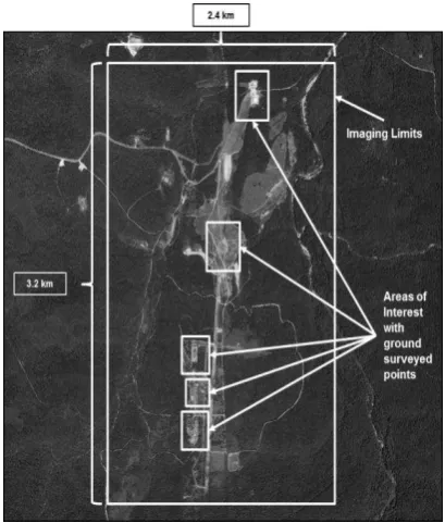
Figure 2. Outline of surveyed test areas on ©2014 Google Earth image
Five small test areas (Figure 2) containing small buildings and shipping containers arranged in various configurations were GPS surveyed for ground truth.
3. DATA
3.1 Data collection
Several photographic test flights using the TBS Discovery quadcopter NGA with modified GoPro lens took place over a two day period. Products have been successfully built from these flights (see next section).
The sparse point clouds below show the variety of collection modes used: racetrack (Figure 3), lawnmower (Figure 4) and circular (Figure 5). The camera was positioned looking down from nadir during the racetrack and lawnmower collections and at 45 degree off-nadir for the circular collections. These sparse clouds with camera positions were captured from Visual Structure from Motion (VisualSFM).
The racetrack collection is best suited for covering large areas of ground for mapping missions while the lawnmower mode involves photographing a specific area. This mode can image an area for both mapping and point clouds in a short time. The circle mode also focuses on a very specific area but with the camera angled optimally can photographic the area for a dense point cloud. Products from all three modes will be tested to help vet the best collection practices.
Figure 6 is a dense point cloud collected from photos from all three flights. This is a VisualSFM point cloud.
Figure 3. Sparse point cloud over northern test area depicting racetrack mode photos looking down from nadir
Figure 5. Sparse point cloud over machine shed in the north-most test area depicting several circular flights at 45 degrees from nadir
Figure 6. Dense point cloud created by VisualSFM, CMVS and PMVS from multiple flights over part of the northern test areas using the NGA quadcopter with a GoPro flat lens camera
4. DATA EXPLOITATION AND PRODUCTS
4.1 Assessments
NGA plans to evaluate several open source and commercial tools and their products for ease of use, quality, and timeliness. Specifically, dense point clouds, 3D models, orthomosaics and digital elevation models (DEM) will be closely assessed. It is understood that not all software can make all products. Positional accuracy (absolute and relative), cameras (electro-optical and infrared) and collection techniques are part of the study.
4.1.1 Tools
NGA is currently using two tools (VisualSFM and Agisoft PhotoScan) and will add at least two more (Urban Robotics TerraFlash 3D and Vision Systems, Inc. Probabilistic 3D Modeling – a voxel approach) in the assessment.
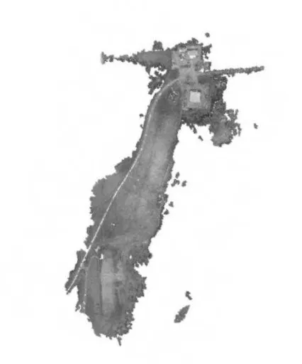
The sparse and dense point clouds (Figures 3 – 7) seen here are from March flights over the test area. They were created using a structured pipeline in Visual Structure from Motion (VisualSFM)(Wu, 2011a, Wu, et al., 2011b), in conjunction with Clustering Views for Multi-view Stereo (CMVS) (Furukawa, et al., 2010) and Patch-based Multi-view Stereo version 2 (PMVS2)(Furukawa and Ponce 2010). VisualSFM includes the scale-invariant feature transform (SIFT) algorithm, feature detection, feature matching and bundle adjustment. CMVS and PMVS2 are also added into the chain to produce dense point clouds such as the ones you see in Figures 6 and 7. Figure 6 shows the results three collections combined into one point cloud. The tools in this pipeline are available as open source.
Figure 7. Dense point cloud created by VisualSFM from single circular flight over machine storage area using the NGA quadcopter with a GoPro flat lens camera
Figure 9. Textured 3D model created by Agisoft PhotoScan from single circular flight over machine storage area using the NGA quadcopter with a GoPro flat lens camera
Figure 7 is another dense point cloud built from 117 photos taken with the GoPro in a single circular orbit around a machine storage area.
PhotoScan is a commercial 3D reconstruction program made by Agisoft. PhotoScan provides a simple step-through process for creating point clouds, polygon models, DEMs, orthophoto mosaics and georeferencing. Figure 8 is the PhotoScan dense point cloud using the same 117 photos. Figure 9 is the same scene as a textured 3D model.
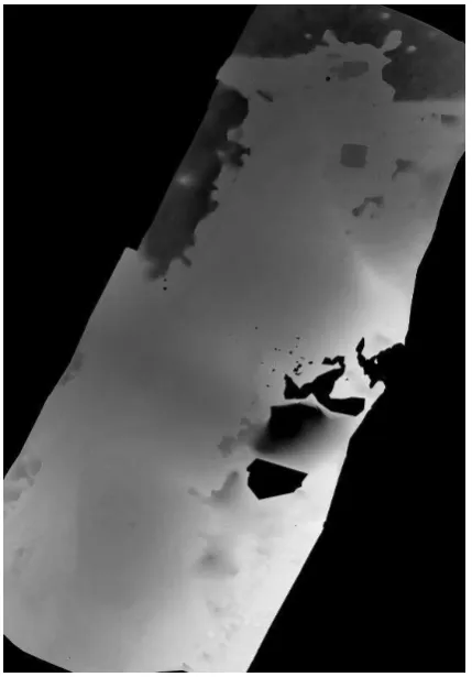
Figure 10. Digital Elevation Model made by CMP-MVS from a NGA quadcopter with a flat lens GoPro camera
Figure 11. Orthophoto mosaic made by CMP-MVS from a NGA quadcopter with a flat lens GoPro camera
Another program, CMP-MVS (Jancosek and Pajdla, 2011), is multi-view reconstruction software that works with VisualSFM outputting a textured mesh of a rigid scene. Additionally, CMP-MVS can output digital elevation models and orthophoto mosaics. See Figures 10 and 11.
The other tools will be discussed in the Future Plans section below.
4.1.2 Products
NGA will specifically look at dense point clouds, 3D model reconstructions, DEMs and orthophoto mosaics. Georeferencing is an important part of the assessment plan. Placing the product as close as possible to the right location on the earth is necessary to the users of the products.
4.1.3 Cameras and collection techniques
A mobile phone camera was used early in the flight testing and found to be suitable for use but did not have the resolution as the other low-cost commercial grade cameras used. Initial ground testing of one of these low-cost cameras provided good photos for these products but was found to not be suitable for flight on the copters due to limited photo triggering mechanism that could be only used by pushing down on the photo button. A mechanical device could be installed but it would impact the weight and electrical requirements.
New commercial grade cameras and another GoPro camera were recently purchased but will be discussed in the Future plans section below.
Lastly, collection techniques are important to the reconstructions, DEMs and orthos. With the first two tests the camera was pointed down from nadir and pointed 45 degrees from nadir for the circle test. It is important that collections be geared toward photographing not only horizontal (rooftops, roads, etc.) but also the vertical surfaces such as sides of features in order to have as much data as possible to create a 3D model. The dense point clouds over the machine sheds in the racetrack and lawnmower modes were less complete than the ones in the circle mode. So a collection strategy will be developed based on a Matlab simulation by Ekholm (2012) that aims the cameras at various degrees from nadir.
5. FUTURE PLANS
5.1 Fixed wing Rascal
The Rascal autopilot and engine has been retrofitted to APM 2.6 and to gasoline.. This will increase the flight endurance from 45 minutes to 3 hours, cut operational costs (1 gallon of Model RC fuel costs approximately $20) and increase safety with the APM autopilot. The Rascal can easily reach altitudes in excess of 1500m where the multirotors will only spend seconds before draining their Li-Po batteries. The Rascal is capable of lifting payloads up to 11kg. Large area coverage with heavier payloads will be tested.
5.2 Updated positional accuracy system
A newly implemented feature of the Pixhawk autopilot system is the implementation of a extended Kalman Filter algorithm to improve positional accuracy of the sUAS. The accuracy will be tested against ground truth.
5.3 Refined collection techniques
Alternative collection paradigms will be compared against survey data for a variety of GEOINT products based on Ekholm’s thesis on airborne collection profiles.
5.4 New cameras
A new commercial grade camera with 16-55mm lens has been ground tested but not flown. This camera is triggered via IR strobe through a device called Strato Snapper 2. The Strato Snapper 2 accepts pulse-width-modulations signals from the Pixhawk or APM and triggers the IR strobe. The Strato Snapper
2 can program the pulse-width modulation signals to cause the IR strobe to trigger different functionalities on the camera, i.e. start and stop video. Future payloads also include a FLIR Tau640 LWIR camera and an Ohio State University owned Velodyne LiDAR system.
5.5 New product software
A CRADA between NGA and Urban Robotics will explore new methods of processing sensor data to increase the development of 3D renderings and maps from sUAV imagery. Probabilistic Volumetric Representation (PVR), a voxel approach, will be tested this fiscal year. Other DEM and orthomosaic generated software accuracy studies are planned. A software program for georeferencing and scaling of point clouds, SfM_georef, by Mike James of Lancaster University, supports VisualSFM. It will also be included in the study.
REFERENCES
Ekholm, J., 3-D Scene Reconstruction from Aerial Imagery, M.S. thesis, Air Force Institute of Technology Air University, Dayton, 168 p.
Furukawa, Y., Curless, B., Seitz, S., Szeliski, R., 2010, Towards Internet-scale Multi-view Stereo, CVPR, 2010 IEEE Conference.
Furukawa, Y. and Ponce, J., 2010, Accurate, Dense, and Robust Multi-View Stereopsis. IEEE Transactions on Pattern Analysis and Machine Intelligence, Vol. 2, Issue 8.
Jancosek, M. and Pajdla, T., 2011, Multi-View Reconstruction Preserving Weakly-Supported Surfaces, CVPR 2011 – IEEE Conference on Computer Vision and Pattern Recognition 2011.
Wu, C., 2011a. VisualSFM: A Visual Structure from Motion System, version 0.5, URL: http://ccwu.me/vsfm, (last accessed 14 August 2014)