APPLICATION OF SFM AND LASER SCANNING TECHNOLOGY TO
THE DESCRIPTION OF MOSAICS PIECE BY PIECE
O.Ajioka a,b*, Y.Hori a
a Dep. of Architecture and Urban Design, Faculty of Human-Environment Studies, Kyushu University, 6-10-1,
Hakozaki, Higashi-ku, Fukuoka-shi, Fukuoka, Japan - [email protected]
b Keisoku Research Consultant CO.,2-10-7, Yanaka, Adachi-ku, Tokyo, Japan - [email protected]
Commission WG V/2
KEY WORDS: SFM(Structure from Motion), laser scanning, comparison, mosaic, Ostia
ABSTRACT:
Mosaic floors of surviving buildings in Ostia have been mainly recorded in photographs. From 2008, Japanese research group carries out a project of 3d measuring of the whole structure of ancient Roman city Ostia using laser scanners, including its landscape, city blocks, streets, buildings, wall paintings and mosaics. The laser scanner allows for a more detailed analysis and a greater potential for recording mosaics. We can record the data of mosaics, which are described piece by piece.However it is hard to acquire enough high dense point cloud and the internal camera of the laser scanner produce low quality images. We introduce a possible technology of 3D recording of mosaics with high-quality colour information; SFM. The use of this technique permits us to create 3D models from images provided from a CCD camera without heavy and large laser scanners. We applied SFM system to different three types of the mosaics laid down on the floors of “the House of the Dioscuroi”, “the Insula of the Muse” and “the House of Jove and Ganymede”, and created high resolution orthographic images. Then we examined to compare these orthographic images with that are created from the point cloud data. As a result, we confirmed that SFM system has sufficient practical utility for the mosaic research. And we present how much of density of point cloud or ground resolution are required for the documentation of mosaics accurately.
* Corresponding author
1. INTRODUCTION
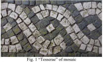
Mosaic floors of surviving buildings in Ostia have been mainly recorded in photographs. From 2008, Japanese research group carries out a project of 3d measuring of the whole structure of ancient Roman city Ostia using laser scanners, including its landscape, city blocks, streets, buildings, wall paintings and mosaics. The laser scanner allows for a more detailed analysis and a greater potential for recording mosaics. The accuracy of laser scanners has been improved year by year and reaches the level that is enough to measure mosaics. Laser scanners are able to create high accuracy dense point cloud stably by non-experts. We can identify each “tesserae”, are the small pieces consisting mosaics, if the point cloud has enough high density. However laser scanners are generally high-cost, heavy and large and it often causes error noise by the influence from the texture of the object surface or the measuring situation. Moreover, the colour information captured by the inside camera of the laser scanner is poor. Chromatic mosaics which survives a lot at Pompeii and a few at Ostia should be measured both its shape and colour from the perspective of reservation or documentation. Mosaic floor has been damaged by the tourists and rain or wind.
In 1980s, the traditional photogrammetry was the one of the most important techniques in the remote sensing field. Even though it has remained great achievements, its complicated manual analysis takes a lot of trouble. In 20 century, laser scanners were widespread also in archaeological field, and they took the place of traditional photogrammetry in many cases. In the other hand, a new technology for creating high accuracy 3D model from multi images, as SFM (Structure from Motion) has been developed in the computer vision field since 1988. It makes possible to create textured 3D models quickly through
the automatic steps below; surveying the feature points from every images, matching these points between two images and estimating the camera position and direction. The image data from CCD cameras are used for the texture of the object directly, therefore the 3D model created from SFM has high reproducibility of the colour information comparing with which has created from laser scanners. In generally, the equipment is simple and low-cost and the investigation term could be shortened.
Fig. 1 “Tesserae” of mosaic
In this paper, our purpose is to introduce how SFM technology can contribute for the documentation of the mosaics. We examined to compare three orthographic images of specific types of mosaics which created from SFM and the laser scanner. The comparing items are below: 1. the accuracy of the planner distance from the rectangular mosaic, 2. the accuracy of height accuracy from the mosaic with height difference, 3. the reproducibility of the colour information from the chromatic
mosaic. Then we present how much of density of point cloud or ground resolution are required for the documentation of mosaics accurately.
2. WHAT IS SFM
Traditional photogrammetry creates pairs of images from overlapped multiple images acquired from different positions, and the camera positions and directions are estimated by applying GCP coordinates manually. It usually requires a prepared calibration data of the camera and it is hard to analyse images acquired by multi cameras and focal lengths in generally. Although the principle of SFM has many points of similarity with traditional photogrammetry and the process of SFM proceeds almost automatically excepting to input the GCP coordinates. It is no need to make the calibration data as the analysis of the producing orthographic images in our project is listed in next chapter.
3. COMPARISON OF THE ORTHOGRAPHIC IMAGES
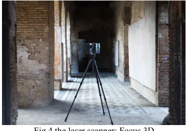
The laser scanner we applied for measuring mosaics is Focus 3D by FARO CO (Fig.4). The accuracy of this laser scanner is
※
M.J.Westoby etc, 2012, Structure-from-Motion’ photogrammetry A low-cost, effective tool for geoscience applications, Geomorphology 179
officially announced ±2mm, we consider that it is enough to record mosaic floors practically. This laser scanner can acquire point cloud in the range of 0.6m-120m and the laser pulse is emitted in all directions excepting the position the laser scanner is placed. Moreover, the colour information can be acquired by the internal CCD camera. We applied the extracted coordinates from the point cloud to the SFM analysis for adjusting the scale and inclination of the 3D model. Therefore it should be paid attention that the comparison introduced in this paper is not comparison with the true value but with accuracy of the laser scanner.
Fig.4 the laser scanner: Focus 3D
3.1 Sample01: Rectangular mosaic
The first sample is a rectangular mosaic which is sized 7.9m*5.9m and laid down at the room10 of the Insula of Muse. It has geometric pattern repeating on the whole surface and has no any other colour tesserae excepting black and white. Rectangular is the most popular shape of mosaics and this mosaic is almost flat. Therefore we examined to check how accurate the orthographic image created from SFM is in planner distance comparing with that of laser scanner. Table1 shows detail information of this SFM analysis.
Fig. 5 Insula of Muse, room 10 Fig. 3 Estimated camera position
Fig. 3 Workflow of SFM
Fig.6 Orthographic image created from multiple images
Fig.7 Orthographic image created from point cloud
Table 1 Detail information of SFM: sample1
Name Insula of Muse room10
Size 7.9m×5.9m approx
Number of images 117 Ground resolution 0.21mm/pix Error of GCP 2.1mm
Sparse point cloud 1256079 pt Dense point cloud 27372588 pt
The result we examined with these orthographic images is listed in table2. We measured the distance between 8 points at the inner side and outer side of the mosaic from both images. The result shows the maximum absolute error is 3.8mm and the accuracy of the distance is calculated 0.052% (0.52mm error per 1000mm).
Table 2 Result of the distance accuracy
Point SFM (mm) Laser scanner
(mm)
Absolute Error
(mm)
AB 3720.4 3721.4 1.0
BC 6131.3 6134.5 3.3
CD 3691.0 3694.8 3.8
DA 6152.3 6150.3 1.9
EF 1174.7 1173.7 1.0
FG 1969.1 1967.7 1.4
GH 1156.4 1156.0 0.4
HE 1962.0 1961.3 0.7
3.2 Sample02: Mosaic with height difference
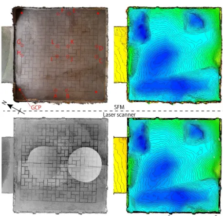
In Ostia, there are some mosaics having height difference in inside for the various reason such as a faculty of the room, by the drainage planning or unexpected transformation like earth quake. In generally, the accuracy of depth direction is lower than the plane accuracy within both laser scanners and photogrammetry. Therefore we examined to compare the accuracy of depth direction using this unevenly mosaic. Furthermore, the contour which is created from SFM and point cloud is compared each other. The object is the geometric pattern mosaic with black and white terrae at the room 7 in the house of Jove & Ganymede. Its whole surface is transformed up and down by any reason as we shows in Fig.8.
Fig.8 House of Jove & Ganymede room6
Fig.9 Orthographic and contour images created from SFM & point cloud
Table.3 Detail information of SFM: sample2 Name House of Jove & Ganymede room 6
Size 4.2m×4.2m approx
Number of images 49
Ground resolution 0.63mm/pix
Error of GCP 1.87mm
Sparse point cloud 337901 pt Dense point cloud 23391437 pt
The result we calculated the Z coordinates of the marked points A-J in Fig.9 is listed below in table.4. The maximum Absolute error is 4.1mm and the mean difference is approximately 2.3mm in 10 points.
Table 4 Result of the height accuracy Poin
t
SFM (mm) Laser scanner (mm) Absolute Error (mm)
A -72837.0 -72835.3 1.7
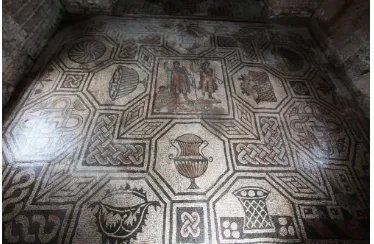
Though almost surviving mosaics in Ostia consist of black and white tesserae, there are a few chromatic mosaics which includes various motifs such as myth, plants or ornaments. Black and white mosaics we introduced previous chapters can be displayed clearly by appearing only intensity of the point cloud as we showed in Fig.7 or 9. Unlike this, chromatic mosaics are should be recorded within both its shape and colour information. There are some laser scanners which can acquire colour information by an optional DSLR not by an internal CCD camera. The coloured point cloud which is acquired by the laser scanner with optional DSLR has clearer colour information than an internal camera. However we can probably say that using acquired images by optional DSLR is not appropriate method for the documentation of chromatic mosaics. That’s why it often makes gaps between the point cloud and the acquired colour information whenever they are merged. The mosaic we introduce in this chapter as a sample is laid down at the room H in the house of Dioscuroi. It represents Castor & Pollux in the center at the near side from the entrance and black and white geometric pattern mosaic at the far side. This mosaic is placed at the next room of the mosaic representing Venus which is one of the most famous mosaics in Ostia.
Fig.10 House of Dioscuroi room H
Fig.11 Orthographic images of the chromatic mosaic created from SFM & point cloud
Table.4 Detail information of SFM: sample3 Name House of Dioscuroi room H
Size 7.4m×6m approx
Number of images 141 Ground resolution 0.47mm/pix Error of GCP 3.82mm Sparse point cloud 666443 pt Dense point cloud 3813697 pt
The orthographic image from point cloud displays some trouble such as losing the colour information and occurring over exposure severely at near of the entrance. Of course it is frequently happen to mistake acquiring images by holding DSLR for the reason as a backlight, reflecting daylight, mistaking camera parameter. However, in practice, when we tried to take photographs of mosaic floor, we usually turn our camera toward down direction. In other word, we can control the direction of camera without any restrictions. Hence, an over exposure is rarely occurred if we pay attention only the direction of camera. In contrast, in the case of acquiring images by laser scanner, an over or down exposure is frequently occurred. That is why almost laser scanners are rotated automatically when it is operated. It is unavoidable to turn the camera toward to the direction which the amount of light is not appropriate since the camera direction is rotated together with the laser scanner.
4. CONSIDERATION
As we introduced in previous chapter, the documentation of the mosaic by using SFM is enough accurate in the planning distance and height and has better reproducibility of the colour information than the laser scanner. In this chapter, we consider that how SFM and laser scanners can contribute to the documentation of mosaics focusing on the technical problem and examine how much of density of point cloud or ground resolution are required. As we mentioned in this paper, what we should record for the documentation of mosaic is the shape and colour of each tessera. We deal with the recording shapes firstly. Acquiring high-density point cloud is necessary to identify
tesserae piece by piece accurately since the size of tesserae is usually approximately 10mm~30mm. Fig.12 shows difference of identifying each tesserae and its arrangement due to the difference of the density of point cloud and the ground resolution of SFM. Left images shows two types of point cloud which has difference density and light images shows three types of orthographic images generated by SFM. In the two images on the left side, we can clearly recognise the shapes of each tessera and their arrangement only in upper image. This high density point cloud has 6988 points per 100cm2 (inside of green line) and the mean distance of each point is 0.4mm. In contrast, it is hard to identify the detail shape of the pieces in the lower image as it shows low density point cloud which has only 1752 points per 100cm2 and the mean distance of each point is 0.8mm. The reproducibility of the shape of tesserae has great influence by the density of point cloud. Almost terrestrial laser scanners emit laser pulses radially so that it is unavoidable to be caused the difference in density in the point cloud. In order to cover this gap, we make effort to control the density by replacing the laser scanner or changing the parameter of laser pulse. Nevertheless, it is hard to make the density of point cloud evenly. Certainly these operations improve the result somewhat, however, increasing the density of point cloud in whole area requires much time for measuring and increasing the amount of the data makes it hard to deal with the point cloud in PC. Moreover, the orthographic images generated from laser scanner always include some circle marks which indicate the position of laser scanner has set as we showed in Fig.11.
In other hand, for SFM one of the most important factors which influences directly to accurate documentation of the shape of mosaics is ground resolution. It will be clear just seeing the three images on the right side in Fig.12. it represents the difference of the ground resolution as 1mm/pix, 2mm/pix, 3mm/pix. In the lower two images, the edges of each tesserae are fuzzy and the arrangement is not clear. Therefore, in case of acquiring images of the mosaic floor, the required ground resolution is about 1mm/pix. Assuming the actual practice, when Canon 60D & 10mm lens are applied to acquire images from 1.6m height, the ground resolution is estimated 0.68mm/pix. Therefore we can say that to satisfy the requirement ground resolution is rather easy compared to that of laser scanner.
Fig.12 the comparison images of the difference of density or ground resolution
Secondly, we consider the documentation of colour information of mosaics. Though there are a few chromatic mosaics in Ostia, it is survived relatively a lot in Pompeii or any other remains. As we introduced at chapter 3.3, the reproducibility of colour information using SFM is better than the laser scanner. The reason is simple as the internal camera has lower performance than DSLR and it is so hard to acquire images with the quality of a constant level. One of the other information which should be recorded for the documentation is a guideline for arranging
a remained guideline under tesserae
The utility of laser scanners should mention here. Although SFM has great potential for measuring floor mosaics as we studied in this paper, when we must create 3D models of a room or whole building with mosaics, it is hard to acquire all of them totally by using only SFM. Two reasons are considerable. One is the human error regarding acquiring images: to be more such as mosaic floors or whole buildings.
5. CONCULUSION
Not only this paper, a comparison with a laser scanner and SFM including traditional photogrammetry is carried out by so many researchers. Certainly we can receive their great achievement accumulated in long history. However, the discussing or gained knowledge in the majority of them was usually confined to general accurate comparison. A technique has its original purpose and it has an object to be achieved. Therefore, we made an example of mosaic measuring in ancient Roman city as a concrete case and examined to compare which is the best tool for documentation of mosaic in SFM or laser scanner. Setting an object such as recording the shape and colour information of small stones piece by piece makes it clear to distinguish the utility of SFM and laser scanner. In this paper, we examined to compare the orthographic images of three floor mosaic. In result, we understand that the planner distance and height accuracy of SFM has enough quality to record mosaics. Moreover, to identify the shape of each tessera from the orthographic images need 0.4mm mean distance in the point cloud in the case of
※
Danbabin, Katherine M.D., Mosaics of Greek and Roman World, London, 1999.
laser scanner and needs at least 1mm/1pix ground resolution in case of SFM. For acquiring colour information, SFM had a great advantage because the images are acquired by DSLR. The internal cameras attached in many laser scanners are less efficient than DSLR generally. Therefore it requests stricter image acquisition condition than DSLR. In other hand, it is a weak point for SFM to reconstructing 3D model of an object which is large or complex such as buildings. It is hard to acquire appropriate huge number of images and to reconstruct these images precisely. In case of that, laser scanners are more suitable.
Lastly we can mention that SFM has high possibility to make some error in the complicated process comparing than laser scanners and it requires a certain level of experienced technique including acquiring images. Nevertheless, it is attractive that SFM can make it possible to record mosaics accurately, in short time, in low cost. In contrast, we can introduce the specific feature of laser scanner as not requiring experienced operator, acquiring high accurate 3D coordinates stable. However, the measuring time takes a long time and it is hard to deal with the point cloud in PC in proportion to make the density of point cloud higher. As the all techniques are so like this, SFM and laser scanners have its own merits and demerits from the technical point of view. We must remember that it is important to use different method or use together them for the different purpose of each project.
REFERENCES
Danbabin, Katherine M.D., Mosaics of Greek and Roman World, London, 1999.
M.J.Westoby etc, 2012, Structure-from-Motion’ photogrammetry A low-cost, effective tool for geoscience applications, Geomorphology 179
D. Skarlatos etc, 2012, Comparison of laser scanning, photogrammetry and SFM-MVS pipeline applied in structures and artificial surfaces
ACKNOWLEDGEMENTS
Thanks are due to Dr. P. Giermoni, the head of Ostia's archaeological superintendency, who granted the permission to work at Ostia, and to Dr. M. Sangiorgio, who provided useful data of GPS in Ostia and I would also like to thank for his advice and help from 2008. I am grateful to engineers in KEISOKU RESEARCH Corp. in Japan, who lent their cheerful collaboration to the task and offered many useful technological comments. This report is a part of the result of a research project, “Architectural History as Reverse Engineering, reading the structural process of ancient Roman architecture and cities“, (director Prof. Yoshiki HORI in Kyushu University), which is financed by J.S.P.S. (Japan Society of Promotion of Science).