44
BAB IV
PERENCANAAN & PERHITUNGAN
4.1 Data Utama Kapal
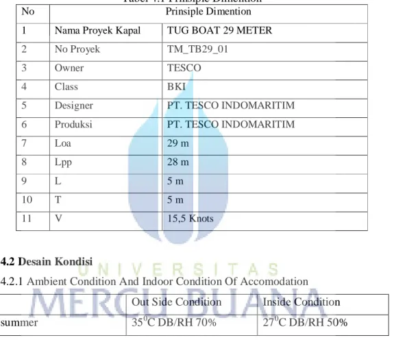
Data utama kapal merupakan ukuran kapal secara umum. Tabel 4.1 Prinsiple Dimention
No Prinsiple Dimention
1 Nama Proyek Kapal TUG BOAT 29 METER 2 No Proyek TM_TB29_01
3 Owner TESCO
4 Class BKI
5 Designer PT. TESCO INDOMARITIM
6 Produksi PT. TESCO INDOMARITIM
7 Loa 29 m 8 Lpp 28 m 9 L 5 m 10 T 5 m 11 V 15,5 Knots 4.2 Desain Kondisi
4.2.1 Ambient Condition And Indoor Condition Of Accomodation Out Side Condition Inside Condition
summer 350C DB/RH 70% 270C DB/RH 50%
4.2.2 suhu air tawar untuk pendingin kondensor = 36o C
4.2.3 Fresh Air Ratio:
1. Summer Seasion: 40% 2. Winter Seasion: 40% 3. Fresh Air 30m3/h/Orang
45 4.3 Perhitungan Beban Pemanasan
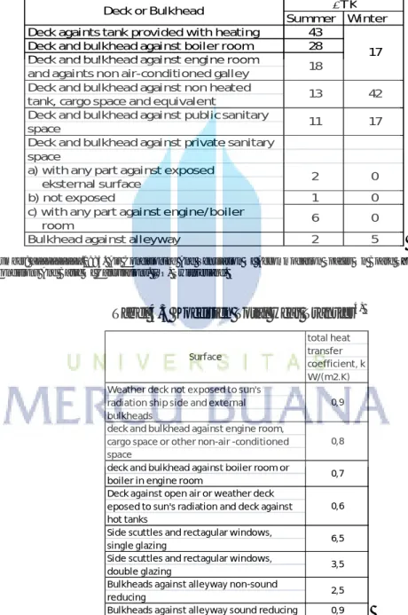
Proses perhintungan dilakukan tiap ruangan yang meliputi transmisi load, lighting load, solar load, personal load, dan equipmen load. Koefisien heat transfer dan perbedaan suhu antar ruangan menggunakan aturan ISO 7547 hal 3 (tabel 4.2 dan tabel 4.3).
Tabel 4.2 Perbedaan Temperatur Antara Ruangan Yang Berdampingan
Summer Winter
Deck againts tank provided with heating 43
Deck and bulkhead against boiler room 28
Deck and bulkhead against engine room and againts non air-conditioned galley Deck and bulkhead against non heated tank, cargo space and equivalent
Deck and bulkhead against public sanitary space
Deck and bulkhead against private sanitary space
a) with any part against exposed eksternal surface
b) not exposed 1 0
c) with any part against engine/boiler room
Bulkhead against alleyway 2 5
Deck or Bulkhead ∆T K 18 17 13 42 11 17 2 6 0 0
Sumber: __________.1985. Air Conditioning And Ventilation Of Accommodation Spaces On Board Ships – Desaign
Conditions And Basic Of Calculations. ISO, Swittzerland.
Tabel 4.3 Koefisien Total Heat Transfer4) total heat transfer coefficient, k W/(m2.K) Weather deck not exposed to sun's
radiation ship side and external bulkheads
deck and bulkhead against engine room, cargo space or other non-air -conditioned space
deck and bulkhead against boiler room or boiler in engine room
Deck against open air or weather deck eposed to sun's radiation and deck against hot tanks
Side scuttles and rectagular windows, single glazing
Side scuttles and rectagular windows, double glazing
Bulkheads against alleyway non-sound reducing
Bulkheads against alleyway sound reducing 0,9 3,5 2,5 Surface 0,9 0,8 0,7 0,6 6,5
Sumber: __________.1985. Air Conditioning And Ventilation Of Accommodation Spaces On Board Ships – Desaign
46 Berikut hasil perhitungan heat load tiap ruangan:
1. Wheel House
47 2. Main Deck
48
49
50
51
52 3. Below Main Deck
53
54
55
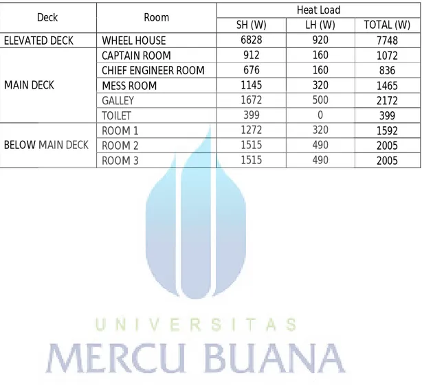
Adapun total heat load untuk masing-masing ruangan baik sensible heat maupun laten heat sebagai berikut:
Tabel 4.13 Total Head Load
Deck Room Heat Load
SH (W) LH (W) TOTAL (W)
ELEVATED DECK WHEEL HOUSE 6828 920 7748
MAIN DECK
CAPTAIN ROOM 912 160 1072
CHIEF ENGINEER ROOM 676 160 836
MESS ROOM 1145 320 1465
GALLEY 1672 500 2172
TOILET 399 0 399
BELOW MAIN DECK
ROOM 1 1272 320 1592
ROOM 2 1515 490 2005
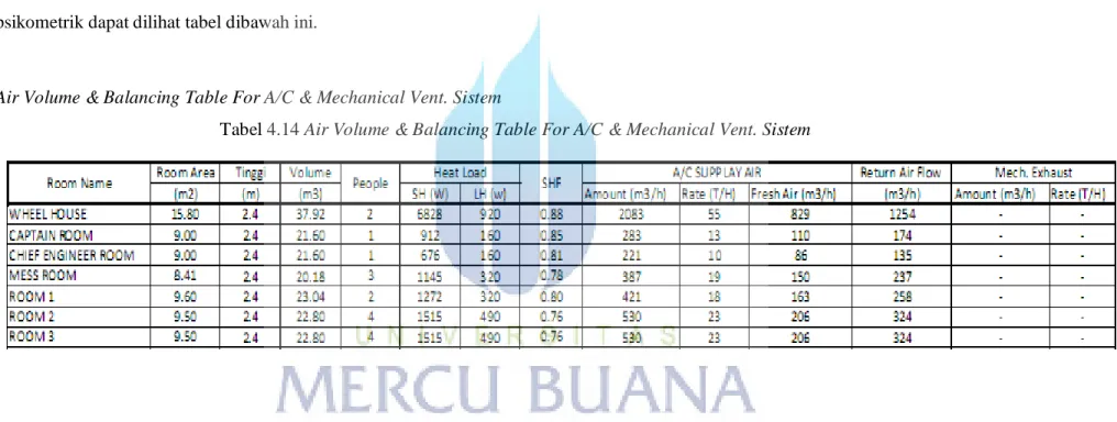
56 4.4 Penentuan Air Volume Balancing
Kapasitas udara yang harus disuplai kedalam ruangan akomodasi diketahui dengan menggunakan analisis psikometrik sehingga diketahui enthalpy dan suhu ADP. proses Analisis psikometrik dapat dilihat pada daftar lampiran A. Adapun hasil perhitungan dari analisis psikometrik dapat dilihat tabel dibawah ini.
Air Volume & Balancing Table For A/C & Mechanical Vent. Sistem
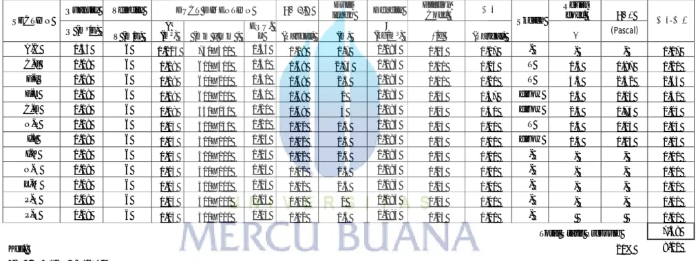
57 4.5 Perencanaa Saluran Udara
4.5.1 Penentuan Dimensi Ducting Ruangan Akomodasi
Tabel 4.15 Dimensi Ducting Ruangan Akomodasi
SECTION
Quantity Velocity DUCT DIMENTION ΔP dim Duct
lengh Dencity Friction Coef. ΔP1 Sketch Resist coef. ΔP2 ΔP1-ΔP2 Q (m³/s) V (m/s) A (m²) (mm x mm ) EQU. L (Pascal) (m) ρ (kg/m³) λ/d (Pascal) ϛ (Pascal) A-C 1.35 6 0.225 750X300 0.43 1.08 1.7 1.184 0.03 0.07 - - - 0.07 C-F 1.08 6 0.18 600X300 0.40 0.69 2.75 1.184 0.11 0.24 T 1.4 0.97 1.21 F-I 1.08 6 0.18 600X200 0.30 0.69 2.5 1.184 0.11 0.21 T 3.5 2.42 2.63 F-L 1.08 6 0.18 600X200 0.30 0.69 2 1.184 0.23 0.37 elbow 1.5 1.04 1.40 C-D 1.08 6 0.18 350X150 0.21 0.69 3 1.184 0.23 0.51 elbow 2.5 1.73 2.24 N-P 0.18 6 0.03 300X150 0.21 0.02 1.5 1.184 0.23 0.01 T 1.4 0.03 0.03 I-J 0.18 6 0.03 300X100 0.15 0.02 1.5 1.184 0.23 0.01 elbow 1.4 0.03 0.03 I-K 0.18 6 0.03 300X100 0.15 0.02 2.4 1.184 0.23 0.01 - - - 0.01 N-O 0.18 6 0.03 300X100 0.15 0.02 1.5 1.184 0.23 0.01 - - - 0.01 L-M 0.18 6 0.03 300X100 0.15 0.02 2.5 1.184 0.23 0.01 - - - 0.01 P-Q 0.18 6 0.03 300X100 0.15 0.02 2 1.184 0.23 0.01 - - - 0.01 P-R 0.18 6 0.03 300X100 0.15 0.02 1.5 1.184 0.23 0.01 - 0.01 Total Static Pressure 7.58
Ket.: 20% 9.10
ΔP dim=ρ/2xW² (Pascal) ΔP1=λ/dxΔP dimxL ΔP2=ϛ x ΔP dim
58
59 4.5.3 Kapasitas Fan Ruang Akomodasi
a. Tekanan Static Pressure FAN adalah 9.10 Pascal = 9.10 N/M2 b. Kapasitas udara Fan minimal adalah 1.35 m3/s
c. Daya Motor Fan = v x ΔP x C : ϛ Dimana :
V = Kapasitas udara ΔP = Total static pressure C = Factor Fan
Ϛ = Isolasi Fan
Daya Motor Fan = 1.35 m3/s x 9.10 N/M2 X 1.15 : 0.6 = 23.5 Watt
60
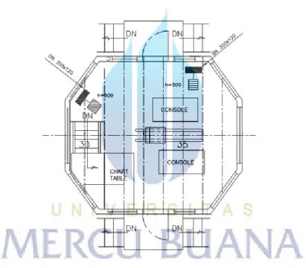
Adapun dari gambar sket diaplikasikan ke gambar general arrangement kapal tugboat adalah sebagai berikut: 1. Whell House
61 2. Bride Deck
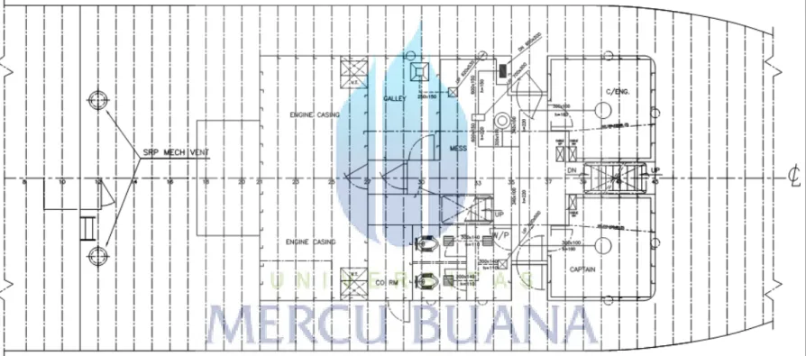
62 3. Main Deck
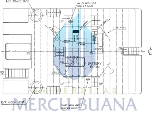
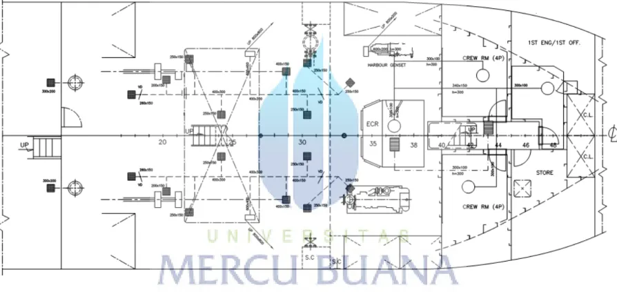
63 4.5.1.1 Below Main Deck
64 4.6 Perencanaan HVAC di Kamar Mesin
Perhitungan kapasitas udara yang disuplai di kamar mesin adalah sebagai berikut:
Tabel 4.16 Dimensi Ducting Ruang Mesin
SECTION
Quantity Velocity DUCT DIMENTION ΔP dim Duct
lengh Dencity Friction Coef. ΔP1 Sketch Resist coef. ΔP2 ΔP1-ΔP2 Q (m³/s) V (m/s) A (m²) (mm x mm ) EQU.
L (Pascal) (m) ρ (kg/m³) λ/d (Pascal) ϛ (Pascal)
A-B 2.16 6 0.36 600x600 0.6 2.76 1.5 1.184 0.05 0.29 - - - 0.29 B-E 1.08 6 0.18 400x300 0.34 0.69 3.5 1.184 0.11 0.29 T 1.4 0.97 1.26 B-H 1.08 6 0.18 400x300 0.34 0.69 3.5 1.184 0.11 0.29 T 1.4 0.97 1.26 C-L 0.27 6 0.045 300x100 0.15 0.04 1 1.184 0.23 0.01 - - - 0.23 D-K 0.27 6 0.045 300x100 0.15 0.04 1.5 1.184 0.23 0.02 - - - 0.23 E-J 0.27 6 0.045 300x100 0.15 0.04 1 1.184 0.23 0.01 - - - 0.23 E-I 0.27 6 0.045 300x100 0.15 0.04 1 1.184 0.23 0.01 - - - 0.23 F-M 0.27 6 0.045 300x100 0.15 0.04 1 1.184 0.23 0.01 - - - 0.23 G-N 0.27 6 0.045 300x100 0.15 0.04 1 1.184 0.23 0.01 - - - 0.23 H-O 0.27 6 0.045 300x100 0.15 0.04 1 1.184 0.23 0.01 - - - 0.23 H-P 0.27 6 0.045 300x100 0.15 0.04 1.5 1.184 0.23 0.02 - - - 0.23
Total Static Pressure 4.36 Ket.:
ΔP dim=ρ/2xW² (Pascal) ΔP1=λ/dxΔP dimxL ΔP2=ϛ x ΔP dim
65
66
67 4.5.3 Kapasitas Fan Ruang Mesin
a. Tekanan Static Pressure FAN adalah 4.36 Pascal = 4.36 N/M2 b. Kapasitas udara Fan minimal adalah 2 x 2.16 m3/s
c. Daya Motor Fan = v x ΔP x C : ϛ Dimana :
V = Kapasitas udara ΔP = Total static pressure C = Factor Fan
Ϛ = Isolasi Fan
Daya Motor Fan = 2.16 m3/s x 2.52 N/M2 X 1.15 : 0.6 = 18,1 Watt
68 4.6 Desain Lay Out HVAC Sentral
69
70