PAPER • OPEN ACCESS
Modeling of the minimum variable blank holder
force based on forming limit diagram (FLD) in
deep drawing process
To cite this article: S Candra et al 2017 IOP Conf. Ser.: Mater. Sci. Eng.273 012014
View the article online for updates and enhancements.
Related content
Determination of forming limit diagrams of AA6013-T6 aluminum alloy sheet using a time and position dependent localized necking criterion
S Dicecco, C Butcher, M Worswick et al.
-Sheet necking prediction in forming limit diagrams with the anisotropy influence incorporation
P Farahnak, A Prantl, J Dzugan et al.
-A Material Perspective on Consequence of Deformation Heating During Stamping of DP Steels
C imir, B Çetin, M Efe et al.
Modeling of the minimum variable blank holder force based
on forming limit diagram (FLD) in deep drawing process
S Candra1, I M L Batan2, W Berata2 and A S Pramono2
1
Department ofManufacturing Engineering, University of Surabaya, Raya Kalirungkut, Surabaya 60293, Indonesia
2
Mechanical Engineering, Institute of Technology Sepuluh Nopember (ITS), Surabaya, Indonesia
E-mail: [email protected]
Abstract. This paper presents the mathematical approach of minimum blank holder force to prevent wrinkling in deep drawing process of the cylindrical cup. Based on the maximum of minor-major strain ratio, the slab method was applied to determine the modeling of minimum variable blank holder force (VBHF) and it compared to FE simulation. The Tin steel sheet of T4-CA grade, with the thickness of 0.2 mm was used in this study. The modeling of minimum VBHF can be used as a simple reference to prevent wrinkling in deep drawing.
1. Introduction
The wrinkle is a type of product defect that often occurs in deep drawing. One thing that can be pursued to prevent product defects is determining the magnitude of the blank holder force (BHF) accurately. To solve this problem, the magnitude of BHF should be set by safe value. Some research related to the determination of blank holder force for prevention product defect is still widely performed. Reddy et al. [1], Agrawal et al. [2], Wang et al. [3], and Qin et al. [4] conducted the research to obtain the linear BHF distribution magnitude for reducing wrinkling. Based on restraining energy calculating and buckling criterion, Agrawal et al. [2], Wang et al. [3] and Qin et al. [4] developed the mathematical modeling of minimum constant BHF to avoid wrinkling. The wrinkling would occur when the buckling strain as the tangential strain is excessive. Furthermore, they have developed the buckling analysis to predict the onset of wrinkling and determined the BHF magnitude by using the theory of strain energy.
Kadkhodaya et al. [5], Chu et al. [6], Correia et al. [7], and Shafaat et al. [8, 9] have proposed the mathematical model of wrinkling by using the approach of bifurcation function and Tresca criterion. Furthermore, these models are used to predict the minimum constant BHF without wrinkling, during the punch stroke. Candra et al. [10] continued these researches to estimate the variable blank holder force by using the maximum gap criterion.
2
2. Mathematical modeling of minimum variable blank holder force
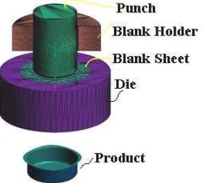
Based on the equilibrium force diagrams in a small element and considering the friction on the flange surface, as shown in Figure 1, the tangential stress equation is obtained as follows [10, 11].
��,� = ��,� - √ + �̅�̅�+�(��) (1) And
��,� = {√ �̅+ �̅�+� σf − , ln , }+{πμFb ,, }-√ �̅+ �̅�+�(��) (2)
Where ��,� is the stress in radial direction, �̅ is average of material anisotropic value, �� � − ,� is the mean flow stress on flange over punch stroke, � ,� is the outer local diameter of flange - function of punch stroke,� is the average radius of cylindrical cup deep drawing, � is the coefficient of friction, ��ℎ,� is the variable blank holder force (VBHF), � is the initial thickness of material and �� is the flow stress a moment on flange.
Figure 1. The equilibrium force diagram in a small element on flange [10, 11].
The mean flow stress on flange over punch stroke (fm,p1-2,i) can be calculated by Eq. (3) [10].
fm,p1-2,i= √ �̅�+
+ �̅� K[(ln ,) + ln t,
D+ d ] (3)
Where �� is the die diameter and � is the die edge radius and d , is the inside diameter.
To determine the changing of diameter should be calculated under the condition a constant volume. The outer local diameter of flange and inside diameter each step could be determined by equation as follows [10, 11].
d , = f (d , dD, r , rd,i=h) = √ d + dD{h − ( , r − , r } (4)
Where r is the punch edge radius, i=h is the punch stroke and d ,can be calculated by Eq. (5),
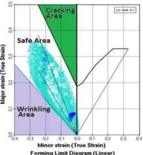
The deformation of deep drawing process can be represented by a minor strain (strain tangential)
Figure 2. Forming limit diagram [19]. Figure 3. Equilibrium of the force
diagram in tangential direction.
Based on defect criterion and the forming limit diagram (FLD), the wrinkling will be predicted when the ratio of minor and major strain around 1.3. In order to achieve these conditions, the equation of tangential stress of each punch stroke also becomes,
t,i= . √ �̅�+
+ �̅� K ((ln ,) + ln
t, ) − ( μ Fb ,
(d , − dD+rd)) (6)
Combining Eqs. (2) and (8), the minimum VBHF (F ,) could be determined with the equation,
F ,= VBHF=
4
Figure 4. Finite Element modeling.
The analytical approach and FE simulation used the detail value of the punch-die dimension, the steel sheet and process parameters, as shown in Table1.
Table 1. Dimension of tools, mechanical properties and variables of processes.
Dimension of tools Mech. properties Tin plate T4 CA Processes parameters
d 64 mm K 559 N/mm 0,45 (dry)
4. Results and discussion: analytical and FE simulation of minimum VBHF
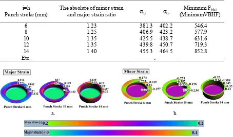
Table 2 shows the magnitude of tangential-radial stress and minimum VBHF by using the equations 1 to 7, based on the minor and major limiting strain ratio, during the punch stroke. A minimum VBHF application under maintaining the strain ratio was effective for controlling the equilibrium of stress deformation. The profile of minimum VBHF increases with an average of gradient slopes around 39.6 to prevent wrinkling.
Table 2. Minimum Fbh,i(VBHF) from analytical based on the limiting strain ratio.
i=h
and minor strain at punch stroke 6, 10 and 14 mm, as shown in Fig. 5. In addition, the minor and major strain ratio can be maintained around 1.3 without excessive wrinkling product. FE simulations prove that the modeling of minimum VBHF could be applied as a reference in deep drawing process without excessive wrinkling. Results of FE simulation have no different significantly compared to the analytical results before.
Table 3. Minimum Fbh,i (VBHF) from FE simulation.
i=h
Punch stroke (mm)
The absolute of minor strain
and major strain ratio t,i I,i
Minimum Fbh,i
(MinimumVBHF)
6 1.23 381.3 402.2 546.4
8 1.25 406.9 423.2 577.9
10 1.35 425.5 438.7 631.6
12 1.35 439.8 450.7 719.3
14 1.40 455.3 464.5 852.8
Etc. Ar A
a. b.
Figure 5. a. Major Strain, b. Minor Strain.
6
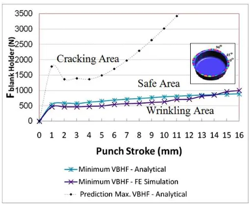
Figure 6. Minimum VBHF vs Punch Stroke.
5. Conclusion
The results of the minimum VBHF calculation are not much different from FE simulation. VBHF could be effective for preventing the occurrence of wrinkling, and also for improving the permeability of the process. VBHF modeling indicated a similar trend compared to FE simulation results. Mathematical modeling of VBHF can be used as a simple approach for estimating the magnitude of minimum blank holder force in every punch stroke. The minimum VBHF has provided the information about a safe area on cylindrical cup deep drawing. Therefore, the safe area must be maintained above the minimum VBHF. Modeling minimum VBHF based on the ratio of minor and major strain and FLD can be used as a reference in the process of deep drawing.
Acknowledgments
The authors would like to acknowledge to Prof. Dr. Dedi Priadi, DEA (Dean of Engineering Faculty - University of Indonesia) for allowing using the AUTOFORM ver. 3.1, and for helpful discussion.
References
[1] Reddy R V, Reddy T A J and Reddy G C M 2012 Effect of various parameters on the wrinkling deep drawing cylindrical cups Int. J. Engineering Trends and Technology 315 pp 53–58 [2] Agrawal A, Reddy N V and Dixit P M 2007 Determination of optimum process parameters for
wrinkle free products in deep drawing process J. Mater. Process. Tech. 191 pp 51–54 [3] Wang X and Cao J 2000 Analytical prediction of flange wrinkling in sheet metal forming J.
Manuf. Process. 2 100–106
[4] Qin S-J, Xiong B-Q, Lu H and Zhang T-T 2012 Critical blank-holder force in axisymmetric deep drawing T. Nonferr. Metal Soc. 22 pp s239–s246
[5] Kadkhodaya M and Moayyedian F 2011 Analytical elastic-plastic study on flange wrinkling in deep drawing process J. of Scientia Iranica Transaction B: Mechanical Engineering 18 pp 250–260
[6] Chu E and Yu X 2001 An elastoplastic analysis of flange wrinkling in deep drawing process Int. J. Mech. Sci. 43 pp 1421–40
[7] Correia J P M and Ferron G 2002 Wrinkling prediction in the deep-drawing process of anisotropic metal sheets J. Mater. Process. Tech. 128 pp 178–190
[9] Shafaat M A, Abbasi M and Ketabchi M 2011 Effect of different yield criteria on prediction of wrinkling initiation of interstitial-free galvanized steel sheet J. of Material and Design 32 pp 3370–76
[10] Candra S, Batan I M L, Berata W and Pramono A S 2015 Analytical study and FEM simulation of the maximum VBHF to prevent cracking on cylindrical cup deep drawing Procedia CiRP
26 pp 548–553
![Figure 1. The equilibrium force diagram in a small element on flange [10, 11].](https://thumb-ap.123doks.com/thumbv2/123dok/3743185.1816457/3.595.219.379.337.537/figure-equilibrium-force-diagram-small-element-flange.webp)