www.tjprc.org [email protected]
DESIGN AND DEVELOPMENT OF CARTESIAN CO-ORDINATE
BASED 3D PRINTER
D. DEV SINGH1 & GOPI RAHUL2 1
Associate Professor, Department of Mechanical Engineering, CMR Institute of Technology /JNTUH Hyderabad, India
2B Tech graduate, Department of Mechanical Engineering, CMR Institute of Technology /JNTUH Hyderabad, India
ABSTRACT
Now a day, manufacturing of complex parts have become a major role in industries. By the use of subtractive processes, there is a lot of scrap and also the accuracy of parts is not up to the mark. So, to eliminate these problems Additive Manufacturing is used, which converts 3D CAD models into physical objects.
3D printer can produce parts layer by layer with the addition of the raw materials used by executing the NC-codes of a CAD designed model, which is controlled by a computer.
In this project work, Design and development of Cartesian co-ordinate based 3D printer is done for the manufacturing of sample parts by using Fused Deposition Modeling (FDM) process. The Fused Deposition Modeling is an advanced manufacturing process uses the thermoplastics, ABS, Poly Vinyl Alcohol (PVA), polycarbonate (PC), PLA (Poly Lactic Acid) and ULTEM 9085. PLA (Poly Lactic Acid) is used as the filament in this project for 3D printing of Mechanical parts and also the above mentioned raw filaments can be used. The parts are modeled in the CATIA V5 R20 software, and it is converted into STL (Stereo lithography) file. By using CURA software, the STL file is converted into G-codes and then it is sent to PRONTERFACE software, which is the interface software between the computer and the Cartesian coordinate based 3D printer. The PRONTERFACE software sends the instructions (i.e. G-codes) to the Cartesian coordinate based 3D printer and the required physical parts can be printed.
KEYWORDS: Additive Manufacturing, CATIA V5 R20,CURA, Design & 3D printer
Received: Nov 24, 2017; Accepted: Dec 15, 2017; Published: Jan 05, 2018; Paper Id.: IJMPERDFEB201830
INTRODUCTION
Introduction to AM
Three-dimensional printers allow quickly making and altering prototypes on their own, or through a company that specializes in rapid prototyping. The ability to design, produce and test products, five or 10 times faster enables designers and entrepreneurs much more creative freedom. In fact, prototyping has become the leading use of 3D printers globally, with the automobile and aerospace industries.
A method of manufacturing known as ‘Additive manufacturing’, due to the fact that instead of removing material to create a part, the process adds material in successive patterns to create the desired shape.
Theme of this Project Work
This project work is done for the purpose of gaining knowledge in oneself and also to impart the knowledge of Additive Manufacturing in the upcoming generations.
264 D. Dev Singh& Gopi Rahul
Impact Factor (JCC): 6.8765 NAAS Rating: 3.11 History
3D printing technology has evolved tremendously in the past few years, but the use of this technology started in the year 1984
1984 Invention of Steriolithography. It is the first 3D printer. 1992 3D Systems produced the first SLA machine
2002 Working 3D kidney created for an animal.
2005 Dr. Adrian Bowyer at The University of Bath found RepRap.
2008 Shapeways launches co-creation service and community which lead to a man to walk with a 3D printed leg.
2009 Organavo uses a Bio 3D printer to print the first blood vessel. 2009 MakerBot starts selling DIY 3D printer.
2011 University of Southampton engineers fly the first 3D printed Aircraft. 2011 KOR ecology unveils Urbee, a prototype 3D printed car.
2012 First 3D printed prostethic jaw implanted.
2013 3D printers used in Household appliances and domestic purposes.
Rapid Prototyping Methods
Rapid Prototyping Technologies are classified as:
Liquid Based Rapid Prototyping Systems
1.3.3.1 Stereolithography 1.3.3.2 Solid Ground Curing
Solid Based Rapid Prototyping Systems
1.3.3.3 Laminated Object Manufacturing 1.3.3.4 Fused Deposition Modeling
Powder Based Rapid Prototyping Systems
1.3.3.5 Selective Laser Sintering 1.3.3.6 Three-Dimensional Printing
Rapid Prototyping Procedure
The Prototyping Procedure is given below:
• Any available CAD software is used for generating desired 3D CAD model and saved as STL file format.
Design and Development of CartesianCo-Ordinate Based 3D Printer 265
www.tjprc.org [email protected] • A thin layer of model is deposited as support structure. The nozzle is moved up for depositing next layer and
completes the model in the subsequent passes.
• The physical object with supports can removed from AM machine.
• The final object is brushed off.
Needs of Rapid Prototyping
• These techniques are currently being advanced further to such an extent that they can be used for low volume economical production of parts.
• It significantly cut costs as well as development times.
Fused Deposition Modeling
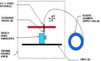
In this modeling, PLA wire of 0.063inch is inserted into the nozzle and nozzle is heated to 1800C. After that, nozzle starts depositing the material on the table. Fist, it creates the support and then desired part. In this project, work nozzle moves up in the z-direction, whereas, the built table has movements in x and y direction. The general sketch of FDM machine is shown below. Some FDM machines use support spools for producing support structures. The diameter of nozzle is 0.75mm.
Figure 1: Fused Deposition Modeling Advantages
• Parts manufactured layer by layer are more accurate and flexible.
• 3D printing reduces the manufacturing lead time.
• The cost of 3D printers is less, any one purchase for specific need.
Disadvantages
• This 3D printer cannot produce all types of parts.
• Higher maintenance cost and skilled operator needed.
3D PRINTER PARTS AND SOFTWARE
Technical Specification
• Printer technology : FFF
266
ource and is compatible with Windows, MAC OS and L
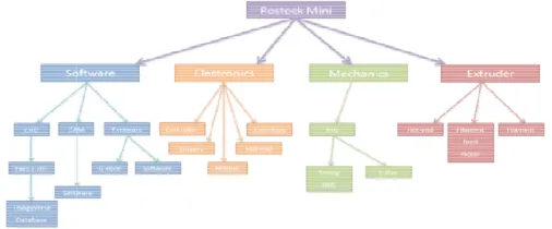
cessitates the combination of software, electronics, and hnologies behind a 3D printer design. This flowchart ca with each other to make the device work together as a un
4.1: Flowchart Illustrating the Working Technologies within the Build of a 3D Printer
ble 3D printer
roviding accurate linear positioning, we need an extrude stic that will soften to a semi liquid state when heated.
Design and Development of CartesianCo-O
lastic filament often, bundled in spools of either 3mm ost, if not all, contemporary filament drivers use a stepp e motors are often geared down with printed gears or an
the strength needed for continued extrusion.
lled into the extruder by the filament driver, is then fed insulated from the rest of the extruder. Nozzle is mad aluminum 6061. When the plastic reaches the hot en n the plastic to be extruded. Once in a semi liquid state, ere in the vicinity of 0.35 millimeters to 0.5 millimeters
Figure 2: Thermoplastic Extruder
ed to all the components and used to operate them. Wh s the central facility that continuously monitors the tem ovements of the stepper motors for the x, y and z movem
268 D. Dev Singh& Gopi Rahul
Impact Factor (JCC): 6.8765 NAAS Rating: 3.11 • Power Supply : 12V, 10A
• Firmware : Repetier Host.
• Softwares : CURA,Pronterface.
SOFTWARE DESCRIPTION LOAD A 3D MODEL
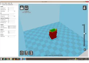
To prepare a 3D model for printing, you first load it into Cura for a Type of Machines by clicking the Load button near the upper left corner of the window. Curafor machines works with STL, the 3D industry standard file format, as well as OBJ, DAE, and AMF files.
The first time you open Cura for a Type Machines, a test 3D model called First PrintCone will be loaded automatically for use as your test print.
Figure 4: A CAD File Loaded Into CURA SLICING AND SAVING 3D MODEL
After every change, you will notice a progress bar in the upper left corner. This is the slice progress. When it’s done your model is ready to be sent to the printer. For large and complicated models, a slice may take a few minutes to complete.
Figure 5: Slicing of 3D Model ASSEMBLY
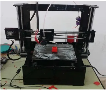
Design and Development of CartesianCo-Ordinate Based 3D Printer 269
www.tjprc.org [email protected] Figure 6: 3D Printer Final Assembly
CONCLUSIONS
These are the conclusions derived from the project.
• 2D and 3D models of the printer parts are designed in the Auto CAD 2010 and in CATIA V5 R20.
• Fabrication and assembly of the Cartesian Co-ordinate based 3D printer is done. The main task during the fabrication and assembly is to assemble the Acrylic frame because the frame plays the major role in the printing of parts with the specified accuracy.
• The Mechanical parts or any part to be printed is first designed in the CATIA software and CURA is used to slice the 3D CAD model into layers.
• 3D sliced Mechanical parts are printed 3D printer using PLA material with the help of interface software Pronterface.
FUTURE SCOPE
The future scope of the 3D printing is given below.
• Fully enclosed Model of 3D printer: Currently, the Cartesian co-ordinate based 3D printers are not enclosed. But, in the future there will be developments made to make the Cartesian co-ordinate based 3D printer fully enclosed.
• Build material: Acrylic is used currently in the frame build material, but in future there will be materials like fibers and other composite materials.
• Software interface: An improved GUI (graphical user interface) can be introduced in the machine which will make it easier to use and user friendly.
• 3D Scanner: As an accessory, a 3D scanner can also be used with the machine.
270 D. Dev Singh& Gopi Rahul
Impact Factor (JCC): 6.8765 NAAS Rating: 3.11 REFERENCES
1. NUR SAAIDAH ABU BAKAR, MOHD RIZAL ALKAHARI, HAMBALI BOEJANG: Analysis on fused deposition modeling
performance
2. SUNG-HOON AHN, MITHCELL MONTERO, DAN ODELL:Anisotropic material properties of FDM
3. R ANITHA, S ARUNACHALAM, P RADHAKRISHNAN:Critical parameters influencing the quality of prototypes in Fused
Deposition Modeling.
4. DAYASHANKAR PRAJAPATI, SWAPNIL NANDWANA, and VIBHOR AGGARWAL: Fused Deposition Modeling.
5. CHRISTIAN WELLER, ROBIN KLEER, FRANK T. PILLER.:Economic Implications of 3D Printing: Market Structure Models
in Light of Additive Manufacturing Revisited.
6. Osama El-Giar, Two Full Multigrid Algorithms in Cartesian and Polar Coordinate Systems to Solve an Elliptic Partial
Differential Equation with a Mixed Derivative Term in a Quarter of a unit Circle, International Journal of Mathematics and
Computer Applications Research (IJMCAR), Volume 4, Issue 6, November - December 2014, pp. 75-86
7. H. LI, G. TAYLOR, V. BHEEMREDDY, O. IYIBILGIN, M. LEU, K. CHANDRASHEKHARA: Modeling and characterization of
fused deposition modeling tooling for vacuum assisted resin transfer molding process.
8. NIKZAD MOSTAFA, HASAN MASOOD SYED, SBARSKI IGOR, GROTH ANDREW:A Study of Melt Flow Analysis of
an ABS-Iron Composite in Fused Deposition Modeling Process.
9. RAPID PROTOTYPING (Laser-based and Other Technologies) by Patri K. Venuvinod and Wei yin Ma, City University of
Hong Kong
10. Chavan D. K. & Tasgaonkar G. S, Study, Analysis and Design of Automobile Radiator (Heat Exchanger) Proposed with Cad
Drawings and Geometrical Model of the Fan, International Journal of Mechanical and Production Engineering Research and
Development (IJMPERD), Volume 3, Issue 2, May - June 2013, pp. 137-146
11. RAPID PROTOTYPING, Principles and Applications; Second edition by CHUA C.K, LEONG K.F and LIM C.S
12. en.wikipedia.org/wiki/3D_printing
13. en.wikipedia.org/wiki/Fused_deposition_modeling
14. www.Reprap.org
15. www.Makerbot.com