USE OF ASSISTED PHOTOGRAMMETRY FOR INDOOR AND OUTDOOR
NAVIGATION PURPOSES
D. Pagliari a*, N.E. Cazzaniga a,L. Pinto a
a DICA-Dept. of Civil and Environmental Engineering, Politecnico di Milano, Milan, Italy
(diana.pagliari, noemi.cazzaniga, livio.pinto)@polimi.it
KEY WORDS: outdoor, indoor, navigation, photogrammetry, Kinect, urban maps, GNSS, depth images
ABSTRACT:
Nowadays, devices and applications that require navigation solutions are continuously growing. For instance, consider the increasing demand of mapping information or the development of applications based on users’ location. In some case it could be sufficient an approximate solution (e.g. at room level), but in the large amount of cases a better solution is required.
The navigation problem has been solved from a long time using Global Navigation Satellite System (GNSS). However, it can be unless in obstructed areas, such as in urban areas or inside buildings. An interesting low cost solution is photogrammetry, assisted using additional information to scale the photogrammetric problem and recovering a solution also in critical situation for image-based methods (e.g. poor textured surfaces). In this paper, the use of assisted photogrammetry has been tested for both outdoor and indoor scenarios. Outdoor navigation problem has been faced developing a positioning system with Ground Control Points extracted from urban maps as constrain and tie points automatically extracted from the images acquired during the survey. The proposed approach has been tested under different scenarios, recovering the followed trajectory with an accuracy of 0.20 m.
For indoor navigation a solution has been thought to integrate the data delivered by Microsoft Kinect, by identifying interesting features on the RGB images and re-projecting them on the point clouds generated from the delivered depth maps. Then, these points have been used to estimate the rotation matrix between subsequent point clouds and, consequently, to recover the trajectory with few centimeters of error.
1. INTRODUCTION
In recent years the use of devices and applications that require accurate navigation solution is continuously growing. For instance, consider the continuous demanding of 3D mapping application based on user’s locations. For some of these application it is sufficient an accuracy of some meters or to know the room where the user is in. However, in the large amount of cases it is fundamental to have a more accurate solution, on the order of few decimetres or even less, as for example for the localization of fireman and paramedical personnel in case of emergencies or the positioning of sensors. Outdoor navigation problem has been solved using GNSS (Global Navigation Satellite System) positioning in the last decades (Hofmann-Wellenhof et al., 2008). Its use has quickly widespread thank to its easiness of use, affordability of cost and capability of reach high accuracies, up to few centimetres. In order to compute a solution a GNSS receiver has to receive signal from at least four satellites, for a period long enough to reconstruct all the information encoded within the transmitted signal. This hypothesis hardly occurred in urban areas because of the presence of obstacles (such as buildings, dense foliage, tunnels, etc.) that obstructed the sky visibility. In these kinds of environments, HSGNSS (High Sensitive GNSS) receivers, having a wider level of sensitivity, could be an interesting solution. However, they could lead to large measurement error (MacCougan, 2003). Furthermore, there are scenarios like downtown areas where there are simply too few satellites in view, with a weak geometry. Concerning the number of visible satellites, for the near future, some improvements are expected using the new constellations Galileo and BeiDou. Often, GNSS antennas are coupled with INS, which are used to estimate position, velocity and orientation of a moving vehicle taking advantages of Newton’s second law of motion. The potentiality
of Mobile Mapping Systems (MMS), and their ability to integrate INS/GPS (Inertial Navigation System/Global Positioning System) data, have been proved from a long time too. See for example Hassan et al., (2006). However, these solutions are very expensive when few decimetres or centimetres of accuracy are required (Al-Hamad and El-Sheimy, 2004). Tactical grade INSs can experience larger position and attitude errors in short time intervals (15 min), when they are used in stand-alone mode or there is a GNSS leakage. A more accurate solution is self-tracking total station, useful for both indoor and outdoor positioning, allowing accuracy on the order of few millimetres (Böniger and Tronche, 2010). Nevertheless, these instruments are quite expensive and require a continuous and clear visibility of the reflector, installed on the object to be tracked. Moreover, the point has to be surveyed from a stable station located at a distance smaller than the maximum instrument operational range, which is usually in the order of some hundred meters. Of course, this condition is difficult to be maintained in urban areas or inside buildings. For indoor environments some high precision solutions already exist, but the cost of the required infrastructures is still prohibitive for high accuracy applications. For instance Ultra Wide Band (UWB) is broadly used for medical applications because it allows to reach even millimetre accuracy (Mahfouz et al., 2008), while other magnetic-based systems allow to reach decimetre level positioning accuracy (Storms et al., 2010). Distances between object and source could be of 0-15 m. Radio Frequency Identification (RFID) (Zhou and Liu, 2007) or Wi-Fi (Vaupel et al., 2010) can potentially provide high accuracy resolutions too, but that accuracy is highly dependent on the number and the spacing among the installed tags. The same considerations can be extended also to the methods based on fingerprints approaches too. In this case the accuracy is strictly
related to the quality of the training phase and from the number of fingerprints stored in the database.
Photogrammetry represents a low-cost solution, suited for both outdoor and indoor environments, which is potentially capable of reaching a high level of accuracy, and not yet fully exploited. The main objective of the work described in this paper is to investigate and develop a low-cost navigation solution based on an inverse photogrammetric approach. Of course, in order to obtain an image-based solution and to scale the photogrammetric problem a number of constrains are required. Moreover, the use of a pure photogrammetric solution can be impossible if only bad textured objects are framed. A possible solution for indoor positing could be to combine the complementary nature of images provided by passive and active sensors, using the Microsoft Kinect sensor for navigation purposes. The paper is organized as follows. In paragraph 2 a brief review of the use of photogrammetry for outdoor and indoor navigation is given. In section 3 the implemented solution for outdoor navigation is presented, together with a complete kinematic test. The approach developed to integrate visual and depth is introduced in paragraph 4. Finally, some conclusion and outlook for future developments are discussed.
2. PHOTOGRAMMETRY FOR NAVIGATION
PURPOSES
The recent wide success of optical based systems is mainly due to the miniaturization and advance in technology of Charged Coupled Devices (CCDs), combined together with a huge increase in the data transmission rate and computational capabilities, as well as the development of imaging processing algorithm. For all these reasons, photogrammetry is commonly used in a variety of fields, reaching different level of accuracies, from sub-millimetre for optical metrology applications for surface inspections or reverse engineering, to tens of meters for positioning using mass-market devices for pedestrian navigation. The use of photogrammetry to define the vehicle trajectory in case of long GPS outages is discussed in Da Silva et al. (2003). They developed a low-cost MMS and used a pure photogrammetric approach to supply GPS outages. Their approach requires using some GPS positions to constrain the perspective centres of extreme stereobases. The use of image-based techniques for GPS outage bridging was also presented in Chaplin (1999) and Tao et al. (2001). In these cases the starting point was assumed to be a known position acquired with solution can be useful only for small GPS outages: along a 300 m long path they experienced a drift up to 1.5 m. According to Eugaster et al. (2012) this results can be improved adding GCPs in suitable locations along the survey. Especially concerning indoor applications, optical based systems can be classified considering how the reference information is obtained (e.g. from building models, coded targets etc.) and if they need any a-priori knowledge. A complete review of these systems can be found in Mautz (2012). For indoor positioning it is quite common to detect object on images and to match them with data stored in a previously populated database, but this approach requires a time expensive survey to collect all the information necessary to populate the database. The real challenge for indoor positioning is represented by autonomous robot navigations: in this case is fundamental to achieve a real-time
solution which is independent from any a-priori knowledge. This problem is commonly known as Simultaneous Location And Mapping (SLAM). Basically, a robot needs to know its location in the environment to navigate between places. SLAM is a typical example of chicken-and-egg problem because in order to localize a camera in the environment it is necessary to have a model of the environment itself but at the same time building the 3D model requires to know the camera poses. The new measurements are sequentially added, so the quality decreases quickly over time. A number of examples of SLAM application can be found in literature, especially in robotics community, fusing together different kind of data to enforce the computed solution. For instance, Ramos et al. (2007) combined together visual and laser data to recognize landmarks, reaching an RMS of 6.8 m. Historically, laser range systems have been mounted on robots to provide the information required for autonomous navigations. The launch on the market of Microsoft Kinect sensor opened up new opportunities for automatic robot guidance because it makes available simultaneously both passive and active imaging sensor data, maintaining low the costs.
3. OUTDOOR NAVIGATION WITH PHOTOGRAMMETRY IN URBAN AREAS
The proposed photogrammetric solution was initially developed in the frame of UMALS project (High Speed 3D Underground Utilities and Automatic Electrical Lying Systems), whose final goal was to perform the automatic lying of medium voltage cables. To perform this procedure it is fundamental to know with very high precision location and geometry of all the existent buried infrastructures, such as ducts, cables etc. Usually, this problem is solved performing a survey with a Ground Penetrating Radar (GPR) pulled by a vehicle or pushed by hand. This instrument has to be georeferenced using external instrumentation. To perform a correct 3D reconstruction of the location and geometry of the buried objects, the GPR has to be georeferenced with accuracy from 0.20 to 0.30 meters. As stressed before, this problem cannot be completely solved in urban areas using GNSS because of the frequent inadequacy of the sky visibility. Moreover, the GPR antenna moves very slowly (in order to meet its sample requirements), so a navigation solution using INS/GNSS will not be feasible because it will be quickly lead to unacceptable drifts. Furthermore, the GPR acquisition is performed acquiring the data along parallel strips, so the residence time in obstructed areas can continue for long periods. The proposed approach investigated the use of photogrammetry, using GCPs extracted from urban maps as constrain, as a possible solution that can overcome GNSS signal leakage in urban areas. The idea of using data extracted from urban maps to improve the navigation solution was already proposed in Crosilla and Visintini (1988), although in a different way. The method discussed in this paper requires one or more digital cameras and a GNSS antenna installed on the same vehicle carrying the GPR (see Figure 1). The inverse photogrammetric problem is solved with a bundle adjustment, using GCPs obtained from urban maps and tie points extracted from the acquired images (e.g. the building located at the roadside are generally characterized by well-textured surfaces). Because both the navigation sensors (digital cameras and GNSS antenna) and the GPR are all rigidly fixed to the vehicle, it is possible to recover the trajectory followed by the georadar. The position of the GNSS antenna phase center and the rigid transformation (rototranslation) from the camera system to a vehicle-fixed reference system are estimated during a geometric calibration phase.
Figure 1. Scheme of the vehicle equipped with two cameras and two GPS antennas used for the kinematic tests
3.1 Preliminary tests
A series of simulation and preliminary tests was realized to evaluate the feasibility of the proposed approach. In Barzaghi et al. (2009) a number of simulation were presented, demonstrating the potential of the proposed photogrammetric solution. Then, a series of tests was conducted to evaluate if Structure from Motion (SfM) techniques can be useful to extract tie points even in challenging urban environment in order to automatically orient even long image sequences, using a quite low number of GCPs. During these tests software EyeDEA (Roncella et al., 2011a, Roncella et al., 2011b) was used to automatically extract homologous points.
A complete preliminary test was presented in Cazzaniga et al. (2012). The test has been realized in conditions very close to the operational ones. The vehicle was equipped with two Nikon D70s cameras (with fixed focal length equal to 20 mm) and a GNSS antenna (to simulate the presence of the GPR and to have a reference trajectory to be used to evaluate the accuracy of the photogrammetric block). The survey has been realized in via Golgi (Milan, Italy) for a total length of 350 m. Eleven GCPs, extracted from urban map, have been used to georeference the photogrammetric block. It was composed by 220 images and the camera projection center have been determined with a bundle block adjustment. The precision were about 0.10 m in all directions. Then, the camera projection center has been transferred in correspondence of the GPS antenna (that simulates the presence of the GPR). The residuals were not smaller than 0.186 m, underlying the presence of a systematic error. This was probably due to the fact that the calibration vector orientation, with respect to the body frame (fixed to the vehicle) has been estimated with a limited accuracy. Furthermore, a trend between the two solutions was clearly visible. This was mainly due to two factors: a drift in the estimation of camera stations and a misalignment between the estimated reference frames. Nevertheless, the photogrammetric solution error was lower than the required tolerance for a 150 m long path. Outside it, the larger residual were mainly due to a degraded GPS accuracy.
3.2 Cremona city block test
During the preliminary test the proposed photogrammetric method has proven to be reliable and the results are in agreement with the accuracy needed to georeference the GPR. However, it clearly emerged that the photogrammetric solution is highly dependent on the quality of the GCPs used to georeference the block. The urban maps are characterized by different accuracy in different town areas; moreover, some outliers could be due to restitution errors or changes in urban environment. Thus, it is essential to integrate in the solution also some GNSS pseudo-observation, allowing outlier identification and rejection. These points could be easily acquired ad the beginning or at the end of the strip or in correspondence of open spaces, such as squares or intersections.
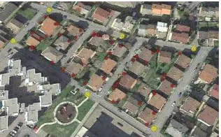
Starting from all this consideration a second kinematic test was realized in a residential area of Cremona city (see Figure 2). The area was selected considering that only low buildings are present there, allowing acquiring a GNSS reference solution during the entire survey. The images have been acquired along close trajectories, to have an auto-consistent photogrammetric solution and to reduce possible drift, experienced during some of the preliminary test discussed so far. The vehicle was equipped with two Nikon D70s digital cameras (with fixed focal length equal to 20 mm) and 2 GPS antennas. The data acquired with one of the antennas was used to evaluate the effect of inserting some GPS pseudo-observations within the photogrammetric bundle block adjustment, while the data of the second antenna was used as a reference solution, simulating the presence of the GPR. The use of two cameras, rigidly fixed to the vehicle, allowed also evaluating the effect of introducing the further constrain of the relative orientation between the two cameras.
Figure 2. The residential area selected for the kinematic test. The selected GCPs are represented in red, while the GPS
pseudo-observations in yellow.
During the survey a total of 600 images have been acquired, with a shooting time equal to one second. The system was geometrically calibrated using a building façade. On this calibration polygon 7 GCPs were previously measured using classical topographic instrumentation. During geometric calibration of the vehicle, images and satellite positions were simultaneously acquired. The components of the lever-arms were computed by comparing the camera projection centres (recovered from the bundle block adjustment) and the GPS positions. The calibration vectors components have been computed with a precision of few centimetres, and were used to insert some pseudo-observation within the bundle block adjustment (Forlani et al., 2005).
A series of different solution, assuming different constrain configurations for the photogrammetric block have been realized. In the first scenario, a pure cartographic constrain has been considered using 52 GCPs extracted from Cremona urban map (1:1000 scale). These points were selected in correspondence of building corners, shelters or pitches. These last points are very important because their height coordinate is very useful to improve the block geometry and stability. The accuracy of the GCPs used was set to 0.20 m for horizontal coordinates and 0.30 m for height, which is typical for 1:1000 scale cartography.
Since it can be reasonably assumed that in some areas, where the sky is more open, it is possible to acquire some GPS positions, we inserted few of them as pseudo-observations within the bundle block adjustment, to better constrain the block itself (GPS solution were obtained via phase double differences, achieving an accuracy of few centimetres). Furthermore, the Relative Orientation (RO) between the two cameras has been considered too. For each one of the evaluated scenario a bundle block adjustment was performed to estimate camera poses, which in turns correspond to the vehicle
trajectory. The photogrammetric problem was firstly solved with the commercial software PhotoModeler® and it was refined with the scientific software Calge (Forlani, 1986), which allows introducing GPS pseudo-observations as well as the relative orientation between cameras. The automatic tie points extraction has been realized with the software EyeDEA. The extracted homologous points were filtered, maintaining an optimal distribution in the image space and preserving their multiplicity too. At the end the block was composed by more than 60,000 image observations, which correspond to about 17,600 object points (with an average multiplicity equal to 3). On average, there were 106 points per image and the image coverage was about 79%. The average number of rays per homologous points was equal to 3 (with a maximum of 22), while the average intersection angle between homologous rays is equal to 17°.
The RMSe computed for the residuals between the estimated position with the photogrammetric approach and the GPS ones, interpolated at shooting time, are reported in Table 1.
N[m] E[m] h[m] 52 cartographic GCP 0.180 0.311 0.260 52 cartographic GCP+ RO 0.195 0.261 0.248 52 cartographic GCP+ 6GPS 0.148 0.140 1.128 52 cartographic GCP+6GPS+RO 0.114 0.092 0.153
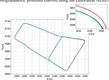
Table 1 - RMSe from the differences between GPS and photogrammetric positions (moved using the calibration vector)
Figure 3. Trajectories estimated considering different photogrammetric block constrains and GPS reference trajectory
(blue represents the GPS reference trajectory, red the photogrammetric trajectory recovered using a pure cartographic
constrain and green the integrated photogrammetric-GPS solution)
From the results reported in Table 1, it is quite evident that the GPR could be better georeferenced inserting some GPS pseudo-observation in the photogrammetric solution, as could be expected. Moreover, the solution improved by adding the further constrain of the relative orientation between the two cameras. A graphic representation of the estimated trajectories, in dependence of three different constrains of the photogrammetric block and the reference GPS trajectory are represented in Figure 3.
4. INDOOR NAVIGATION USING MICROSOFT KINECT SENSOR
The navigation problem for indoor environments has been faced investigating the results obtainable using a low-cost RGB-D depth camera: the Microsoft Kinect sensor. The Kinect was
launched in 2010 by Microsoft Corporation as a remote controller for its Xbox360 console. Unlike other human control devices (such as Nintendo Wii remote control or Sony PlayStation Move) it allows users to play and completely control the console without having to hold any device, but only with the use of voice and gesture. This is possible because during the game the players are continuously tracked and his avatar is moving according to their gestures. Kinect 1.0 is composed by a RGB camera, an IR camera, an IR projector (that projects a random pattern), a microphone, a tilt motor and a 3-axes accelerometer. On summer 2014 a new generation of Kinect, based on time-of flight technology, has been released. This new sensor is made by an RGB camera and an IR camera too, but the depths are computed performing a phase correlation between the emitted and the reflected signals. Microsoft Kinect had immediately a large diffusion being used in number of applications different from the original idea of a 3D human interface. In fact, the launch on the market of Kinect sensor extended the use of RGB-D camera to low cost projects, solving many navigation problems by integrating visual and depth data, which can reciprocally compensate their weaknesses. According to the specific environment that has to be explored, visual or depth data can represent a good solution or not. Generally, RGB images can be profitably used if there is a strongly chromatic variation or objects with highly distinctive textures. On the contrary, in case of uniformly plastered walls it can be very difficult to extract features. Instead, point clouds can be very useful in situation with low image contrast. However, in order to align the 3D models created from the acquired depth data it is necessary to have some volume variations in the frame scene (e.g. presence of furniture, room corners etc.).
The complementary nature of the gathered data and the low-cost make Kinect sensor very appealing, especially for robot navigation purposes and 3D model reconstruction.
4.1 Integration of visual and depth images
In literature, a number of applications based on the use of RGB and depth data can be found. See for examples Oliver et al. (2012), Endres et al. (2012). Usually the proposed solutions are based on SLAM approaches, mainly because for robot navigation a real time solution is required. However, the accuracy of the estimated trajectory decreases quickly because the estimation of the camera poses accumulates errors over time. Moreover, the large majority of the available studies about the use of Kinect for navigation purposes are strictly connected to Computer Vision communities, so it is very difficult to find information about system calibrations or the precision of the implemented approach. The solution here presented is not meant to be in real time, however the choice was driven mainly by the time requested to compute the followed trajectory. SIFT (Lowe, 2004) is the most common used interest operator because of its good performances. In fact it is highly features distinctive and it generally outperforms other interest operators, however its matching phase requires a large amount of time, especially for long image sequences, like the ones acquired by Kinect sensor. On the other hand, KLT tracking algorithm (Lucas and Kanade, 1981 - Tomasi and Kanade, 1991) can track features very quickly, but in the original implementation the points are extracted using a corner detector. Hence, it could be hard to track a high number of good features in case of homogenous frame scene. Starting from this consideration a new software has been realized. The new implemented software uses KLT algorithm, but the points tracked are extracted with more reliable interest operators, such as SIFT. Then RBG and depth images are integrated in order to reconstruct the followed
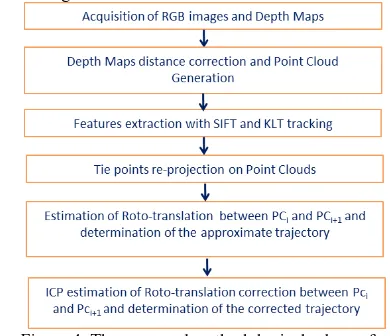
trajectory. A comprehensive schematic view of this approach is given in Figure 4.
Figure 4. The proposed methodological scheme for recovering Kinect trajectory
4.2 Kinematic test with Kinect for XboxOne
A kinematic test was realized using the new version of Microsoft sensor. Kinect for XboxOne was placed on a cart, which has been moved in a corridor of an office building. The sensor was installed on a tripod (which was in turn fixed to the cart). On the same vehicle a reflective prism was installed too (see Figure 5). The cart was automatically tracked using a self-tracking Topcon Is203 total station, in order to have a reference trajectory for evaluating the reliability of the results. The system was geometrically calibrated acquiring simultaneously images from both the visual sensors (IR and RGB camera) and at the same time tracking the prism positions. The cart was slowly moved and, during the survey, depth and RGB images have been acquired simultaneously by Kinect 2.0. It was remotely controlled with in-house coded software based on Microsoft SDK and installed on a laptop. The data were processed using the methodological workflow presented in Figure 4.
Figure 5. The Kinect installed together with the laptop and the reflective prism on the cart
By solving the exterior orientation of the first IR frame it is possible to recover the trajectory directly in object reference system (XYZ). Once the trajectory is computed, it can be transferred to the prism reference point using the lever arm estimated during the geometric calibration.
The trajectory computed using KLT-SIFT tracking algorithm and the one refined using ICP algorithm, transferred to the reflective prism are reported in Figure 6. In the same figure is plotted also the reference trajectory, acquired with the self-tracking total station. The results show that there is a good consistency between the Kinect 2.0 solution and the reference one since the RMSs of the discrepancies in all the coordinates
are lower than 0.05 m (see Table 2). These results are in agreement with the precisions of the relative orientation parameters (between the IR and the RGB camera) and of the 3D-vector connecting the cameras and the reflective prism, reached during cart calibration phase. The ICP corrections were not significant because they were of the same order of magnitude than the error committed by Kinect 2.0 sensor when it is used as a depth measuring system.
Figure 6. Trajectories estimated with the Kinect using the proposed integrated solutions
X[m] Y[m] Z[m] RMSe KLT-SIFT Kinect 2.0
trajectory 0.047 0.035 0.038 RMSe KLT-SIFT Kinect 2.0
trajectory +ICP correction [m] 0.046 0.030 0.029 Table 2 - RMSe of GPR position between the Kinect 2.0 solution (transferred using the calibration vector) with respect
to the trajectory followed by the reflective prism.
5. CONCLUSIONS
Both the solution here presented has been proven reliable to recover a trajectory in obstructed area, even though this solution is very dependent on the possibility of tracking at least few points throughout the entire image sequence. For outdoor navigation, photogrammetry has emerged as a reliable solution for georeferencing a slow moving vehicle with an accuracy of few decimeters while having an up-to-date and correct large scale map.
For the indoor case, the example of Kinect sensor has clearly shown that the integration of visual and depth data can be helpful to overcome possible weaknesses of a pure photogrammetric solution, in environments with poor texture. The proposed method allowed recovering the followed trajectory with an error of few centimeters, but it could be improved using RGB-D descriptors in order to have good performances in all situations.
ACKNOWLEDGEMENTS
The authors thank 3DOM unit at Bruno Kessler Foundation for providing the software Rotoprocuster_scaling and for the help provide during the development of the indoor navigation solution.
REFERENCES
Al-Hamad, A., El-Sheimy, N.,. 2014. Smartphones Based Mobile Mapping Systems. In: The International Archives of Photogrammetry and Remote Sensing and Spatial Infor mation
Sciences. Vol. XL-5, Proceedings on the ISPRS Technical Commission V Symposium, Riva del Garda, Italy.
Barzaghi, R., Carrion, D., Cazzaniga, N.E., Forlani, G., 2009. Vehicle Positioning in Urban Areas Using Photogrammetry and Digital Maps, Proceedings of the ENC-GNSS09, Napoli.
Böniger, U., Troncke, J., 2010. On the Potential of Kinematic GPR survey Using Self-Tracking Total Station: Evaluating System Crosstalk and Latency. IEEE Transaction on Geoscienze and Remote Sensing. Vol. 28, n. 10, pp. 3792-3798.
Cazzaniga, N.E., Pagliari, D., Pinto, P., 2012. Photogrammetry for Mapping Underground Utility Lines with Ground Penetrating Radar in Urban Areas. In: International Archives of the Photogrammetry, Remote Sensing and Spatial Information Sciences. Volume XXXIX-B1, Melbourne, Australia
Chaplin B., 1999. Motion Estimation from Stereo Image Sequences for a Mobile Mapping System. Msc. Thesis, Department of Geomatics Engineering, University of Calgary.
Crosilla, F., Visentini, D., 1998. External Orientation of a Mobile Sensor via Dynamic Vision of Digital Map points. Bollettino di Geodesia e Scienze Affini. 57(1), pp.41-60.
Da Silva, J.F. de Oliviera Carmago, P., Gallis R. B. A., 2003. Development of a low-cost mobile mapping system: a South American experience. The Photogrammetric Record. Vol. 18 (101), pp. 5-26.
Endres, F., Hess, J., Engelhard, N., Sturn, J., Cremer, D., Burgard, W., 2012. An Evaluation of RGB-D SLAM System. 2012 IEEE International Conference on Robotics and Automation. River Centre, Saint Paul, Minnesota.
Eugster, H., Huber, F., Nebiker, S., and Gisi, A., 2012. Integrated georeferencing of stereo image sequences captured with a stereovision mobile mapping system – approaches and practical results. In: International Archives of Photogrammetry Remote Sensing and Spatial Information Sciences. XXXIX-B1, pp. 309-314.
Forlani, G., 1986. Sperimentazione del nuovo programma CALGE dell’ITM. In: Bollettino SIFET. No. 2, pp. 63-72
Forlani G., Roncella R., Remondino F., 2005. Structure and motion reconstruction of short mobile mapping image sequences. Proc. of the 7th Conf. On Optical 3D measurement techniques. Vol I, pp. 265-274.
Hassan, T., Ellum, C., El-Sheimy, N., 2006. Bridging land-based mobile mapping using photogrammetric adjustments. ISPRS Commission I Symposium. From Sensors to Imagery.
Hoffmann-Wellenhof, B., Lichtenegger, B., Walse, E., 2008. GNSS- Global Navigation Satellite Systems. SpringerWeinNewYork.
Lowe, D., 2004. Distinctive Image Feature from Scale-Invariant. International Journal of Computer Vision. 60(2), pp. 91-110.
Lucas, B.D., Kanade, T., 1981. An Iterative Registration Techniques with an Application to Stereo Vision, Proceedings
of 7th International Joint Conference on Artificial Intelligence. (AJCAI) 1981., pp. 674-679.
MacGougan, G. D., 2003. High Sensitive GPS Performance Analysis in Degraded Signal Environments. M.Sc Thesis. Department of Geomatics Engineering, University of Calgary.
Mautz, R. (2012). Indoor Positioning Technologies. Habilitation Thesis at ETH Zurich, 127 p, Swiss Geodetic Commission, Geodetic-Geophysical Reports of Switzerland, no. 86, ISBN 978-3-8381-3537-3.
Mahfouz, M.R., Zhang, C., Merkl, B.C., Kuhn, M.J., FAthy, A. E., 2008. Investigation of High-Accuracy Indoor 3d Positioning Using UWB Technology. IEEE Transaction on Microwave Theory and Techniques, Vol. 56 (6), June 2008.
Oliver, A., Kong, S., Wünsche, B., MacDonald, B., 2012. Using the Kinect as a Navigation Sensor for Mobile Robotics. Proceedings of the 27th Conference on Image and Vision Computing, pp. 505-514.
Ramos, F.T.; Nieto, J.; Durrant-Whyte, H.F., 2007. Recognizing and Modelling Landmarks to Close Loops in Outdoor SLAM. 2007 IEEE International Conference on Robotics and Automation, pp.2036-204.
Roncella, R., Re, C., Forlani, G., 2011. Comparison of two Structure from Motion Strategies. In: International Archives of Photogrammetry, Remote Sensing and Spatial Information Science, vol. XXXVIII, 5-W16.
Roncella, R., Re, C., Forlani, G., 2011. Performance Evaluation of a Structure and Motion Strategy in Architecture and Cultural Heritage,. In: Archives of Photogrammetry, Remote Sensing and Spatial Information Sciences. ISPRS volume XXXVIII-5/W16.
Roncella, R., Remondino, F., Forlani, G., 2005. Photogrammetric Bridging of GPS outages in mobile mapping. Electronic Imaging. pp.308-319.
Storms, W., Shockley, J., Raquet, J., 2010. Magnetic Fields Navigation in Indoor Environment. Proceeding of Ubiquitous Positioning Indoor Navigation and Location Ba sed Service. (UPINLBS), pp 1-10.
Tao, C. V., Chapman, M. A., Chaplin, B. A., 2001. Automated Processing of Mobile Mapping Image Sequences. ISPRS Journal of Photogrammetry and Remote Sensing. vol. 55, pp 330-346.
Tomasi, C., Kanade, T., 1991. Detection and Tracking of Point Feature. Carnegie Mellon University Technical Report, CMU-CS-91-132, April 1991.
Vaupel, T., Kiefer, J., Haimerl, S., Thielecke, J., 2010. Wi-Fi Positioning Systems Consideration and Devices Calibration. 2010 International Conference of Indoor Positioning and Indoor Navigation (IPIN).
Zhou, Y., Lui, W., 2007. Laser-Activated RFID-based Indoor Localization System for Mobile Robots. Proceedings of the 2007 IEEE International Conference on Robotics and Automation. Rome. Italy, 10-14 April.