APPLICATION OF VEHICLE DYNAMIC MODELING IN UAVS FOR PRECISE
DETERMINATION OF EXTERIOR ORIENTATION
M. Khaghania∗, J. Skalouda
a
EPFL ENAC IIE TOPO, Bˆatiment GC, Station 18, 1015 Lausanne, Switzerland - (mehran.khaghani, jan.skaloud)@epfl.ch
ICWG III/I
KEY WORDS:Sensor Orientation, Precise Attitude Determination, Navigation, UAV, Corridor Mapping, Vehicle Dynamic Model
ABSTRACT:
Advances in unmanned aerial vehicles (UAV) and especially micro aerial vehicle (MAV) technology together with increasing quality and decreasing price of imaging devices have resulted in growing use of MAVs in photogrammetry. The practicality of MAV mapping is seriously enhanced with the ability to determine parameters of exterior orientation (EO) with sufficient accuracy, in both absolute and relative senses (change of attitude between successive images). While differential carrier phase GNSS satisfies cm-level positioning accuracy, precise attitude determination is essential for both direct sensor orientation (DiSO) and integrated sensor orientation (ISO) in corridor mapping or in block configuration imaging over surfaces with low texture. Limited cost, size, and weight of MAVs represent limitations on quality of onboard navigation sensors and puts emphasis on exploiting full capacity of available resources. Typically short flying times (10-30 minutes) also limit the possibility of estimating and/or correcting factors such as sensor misalignment and poor attitude initialization of inertial navigation system (INS). This research aims at increasing the accuracy of attitude determination in both absolute and relative senses with no extra sensors onboard. In comparison to classical INS/GNSS setup, novel approach is presented here to integrated state estimation, in which vehicle dynamic model (VDM) is used as the main process model. Such system benefits from available information from autopilot and physical properties of the platform in enhancing performance of determination of trajectory and parameters of exterior orientation consequently. The navigation system employs a differential carrier phase GNSS receiver and a micro electro-mechanical system (MEMS) grade inertial measurement unit (IMU), together with MAV control input from autopilot. Monte-Carlo simulation has been performed on trajectories for typical corridor mapping and block imaging. Results reveal considerable reduction in attitude errors with respect to conventional INS/GNSS system, in both absolute and relative senses. This eventually translates into higher redundancy and accuracy for photogrammetry applications.
1. INTRODUCTION
A novel autonomous navigation for unmanned aerial vehicles based on vehicle dynamic model recently introduced by the au-thors in (Khaghani and Skaloud, 2016), focused on reducing nav-igation error in GNSS outage conditions. This contribution ex-plores the possibility of using that method in presence of high accuracy GNSS solution to improve attitude determination accu-racy for photogrammetry applications, compared to conventional INS/GNSS integration. A shortened introduction on principles of the proposed method is presented in Section 2 and Section 3, while the main part of the contribution is presented in Section 4 and focuses on results and discussions related to attitude determi-nation accuracy in block and corridor mapping scenarios.
1.1 Motivation
Employing UAVs for photogrammetry is very popular nowadays (Colomina and Molina, 2014). Using MAVs has considerably de-creased cost and effort needed for photogrammetry tasks during the filed operations. On the other hand, observation of camera position/attitude can facilitate the post processing tasks once the photos are taken. In order to achieve ground errors under ground sampling distance (GSD) levels, the level of required accuracy for EO parameters is rather demanding. This is more crucial for DiSO, since any error on EO parameters directly translates into a ground error. For example, an error of0.05◦in roll or pitch for a flight altitude of150mmeans a ground error as big as13cm.
With high accuracy carrier-phase differential GNSS positioning, the requirements on positioning accuracy are usually met (Rehak
∗Corresponding author
et al., 2013). However, achieving the accuracy requirements on attitude is still challenging with MEMS IMUs typically found on MAVs. Any improvement on attitude determination accuracy is directly reflected in the accuracy of final ortho-photo product in case of DiSO, and can reduce the number of required ground con-trol points (GCP) in case of ISO, especially in corridor mapping scenario (Rehak and Skaloud, 2015). For this reason, a novel VDM based navigation method is employed in this research to improve attitude determination for a MAV. Attitude control is ab-solutely necessary for sensors such as LiDAR and pushbroom scanners, and it is useful/necessary for frame cameras in case of low or no lateral overlap, low number of GCPs, and over low surface texture (i.e., low number of tie points).
Using relative attitude and position data is a rather new approach in airborne mapping (Bl´azquez, 2008) that has practical applica-tion in MAVs (Skaloud et al., 2014). In ISO, it brings some ad-vantages such as elimination of the need for camera-to-IMU bore-sight calibration and removing the effect of positioning biases if present. For this reason, the simulation results are presented for both absolute and relative attitude determination approaches in current paper.
1.2 Proposed approach
no additional sensors compared to conventional INS/GNSS setup. Therefore, its employment represents no additional cost and weight on the platform, which is an important aspect in small UAVs.
The VDM needs to be fed with the control input to the UAV. This information is already available in the control/autopilot sys-tem, but it needs to be put in correct time relations with IMU and other measurements in real life implementation. The other input to VDM is the wind velocity. The proposed solution makes it possible to estimate the wind velocity within the navigation filter itself, even in absence of air pressure sensors. This adds certain redundancy to the system in case of air pressure sensor misbe-havior or failure when employed.
The VDM requires a proper structure based on the host platform type (fixed wing, multicopter, etc.) and its control actuators, which is well described in the literature (Cook, 2013) (Ducard, 2009). The model parameters depend on the specific platform. They can be either identified and pre-calibrated, or estimated in-flight. This capability for online parameter estimation (dynamic model identification) that does not require pre-calibration, mini-mizes the effort required in design and operation.
The proposed navigation system was shown to significantly im-prove the accuracy and mitigate the drift of position, velocity, and attitude uncertainty during GNSS signal reception absence (2 orders of magnitude for positioning and 1 to 2 orders of mag-nitude for attitude determination) (Khaghani and Skaloud, 2016). However, the benefits of employing this system are not limited to GNSS outage conditions. Therefore, we investigate attitude de-termination improvements provided by this approach when high accuracy GNSS solution is available over the entire trajectory as a potential impact on the quality of ISO and especially DiSO with small UAVs.
2. VEHICLE DYNAMIC MODEL
A brief description of the model is presented here, along with the key definitions and equations. More details can be found in (Ducard, 2009) and (Khaghani and Skaloud, 2016).
2.1 Definitions
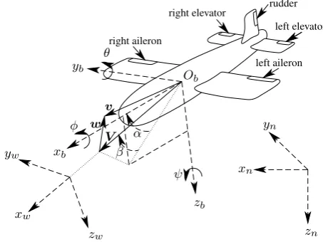
Three coordinate frames are considered in this research, “nav-igation”, “body”, and “wind” frames. The navigation frame is a local-level frame oriented in north, east, and down directions denoted by(xn, yn, zn)or(xN, xE, xD), and considered to be inertial. Definitions of body frame and wind frame(xb, yb, zb) can be perceived from Figure 1. The rotation matrix to transform vectors from body frame to navigation frame is defined as a func-tion of roll(φ), pitch(θ), and yaw(ψ)angles.
The wind frame has its first axis in direction of airspeedV, and is
defined by two angles with respect to body frame, angle of attack
αand sideslip angleβ. Velocity of airflow that is due to UAV’s inertial velocityvand wind velocitywis denoted by airspeed
vectorV as
Figure 1: Navigation, body, and wind frames with airspeed (V),
wind velocity(w), and UAV velocity (v), as weel as roll (φ), pitch
(θ), and yaw (ψ)
The rotation matrix from body frame to wind frame is defined as a function of angle of attack and sideslip angle as
Rw
The density of the air is calculated based on the International Standard Atmosphere model as a function of local pressure and temperature, which can be expressed as functions of the altitude as detailed in (Khaghani and Skaloud, 2016).
2.2 Dynamic model
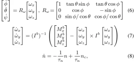
The VDM employed in this research is based on rigid body dy-namics for a fixed wing UAV, considering polynomial models for aerodynamic forces and moments (Ducard, 2009). The state vectorXn=xN, xE, xD, vbx, vby, vzb, φ, θ, ψ, ωx, ωy, ωz, nT, respectively. Deflections of aileron, elevator, and rudder are de-noted byδa,δe, andδr, respectively. Propeller speed is denoted byn, wherencshows the commanded value for that, andτnis the time constant for its dynamics. Kinematic equations, New-ton’s equations of motion, and a first order model for propeller dynamics form the vehicle dynamic model as
denote mass and moments of inertia matrix of the UAV, respectively. The four aerodynamic forces and the three aerodynamic moments are expressed as polynomial functions of navigation states, control inputs, wind velocity, and physical prop-erties of the UAV called dynamic model parameters hereafter. The aerodynamic forces include:
• “thrust force” asFT =f(ρ, V, D, n, CFT...) The aerodynamic moments include:
• “roll moment” asMb
x=f(ρ, V, S, b, CMx..., δa, β, ωx, ωz) • “pitch moment” asMyb=f(ρ, V, S,¯c, CMy..., δe, α, ωy • “yaw moment” asMzb=f(ρ, V, S, b, CMz..., δr, ωz, β) Propeller diameter is denoted byD, andS,b, andc¯represent wing surface, wing span, and mean aerodynamic chord, respec-tively. Density of air is shown byρ, andC...’s represent aerody-namic coefficients for associated force and moment components. The vehicle dynamic model parameters are collected in (9).
3. FILTERING METHODOLOGY
An extended Kalman filter (Gelb, 1974) is chosen to serve as the navigation filter in this research, which is detailed in this section.
3.1 Scheme
The proposed navigation system utilizes VDM as main process model within a differential navigation filter. As depicted in Fig-ure 2, VDM provides the navigation solution, which is updated by the navigation filter based on available measurements. Hence, IMU output is treated as a measurement within the navigation filter, just the way GNSS observations are, whenever they are available. Any other available sensory data, such as altimeter or magnetometer output, can also be integrated within the naviga-tion filter as addinaviga-tional observanaviga-tions. VDM is fed with the con-trol input of the UAV, which is commanded by the autopilot and therefore available. Other needed input is the wind velocity as an input, which can be estimated either by the aid of airspeed sensors, or within the navigation system with no additional sen-sors needed. The latter approach is investigated here. Finally, the parameters of VDM are required within the navigation filter. Pre-calibration of these parameters as fixed values is an option. However, to increase the flexibility, as well as the accuracy of the proposed approach while minimizing the design effort, an on-line parameter estimation/refinement is implemented. Last but not least, IMU errors are also modeled and estimated within the navigation system as additional filter states.
3.2 State space augmentation
The augmented state vector includes the navigation statesXn,
the UAV dynamic model parametersXpexcluding mass(m)and
moments of inertia (Ix, Iy, Iz, Ixz), the IMU error termsXe, and the wind velocity componentsXw.
*
Figure 2: Navigation system architecture
The dynamic model parameters are included in a26×1state vector as in (9), and modeled as constant parameters with initial uncertainties. Description of these parameters is provided in the nomenclature, and the numerical values used in simulation can be found in (Ducard, 2009).
Xp= Mass and moments of inertia are not included in this vector, since they appear as scaling factors in equations of motion and there-fore they are completely correlated with the already included co-efficients of aerodynamic forces and moments.
The error in each accelerometer and gyroscope inside the IMU is modeled as a random walk (b...
rw) process. Therefore, the IMU error terms vector is defined as
Xe=barw1, barw2, barw3, bgrw1, bgrw2, bgrw3T, (10)
whereaiandgisuperscripts denote thei-th accelerometer and gyroscope, respectively. This model has been found sufficient for the low-cost IMU in consideration, but can be extended as needed.
The wind velocity is stated as a vector in local (navigation) frame consisting of the three components of wind velocity in north, east, and down directions.
Xw= [wN, wE, wD]T (11)
Wind velocity is also modeled as a random walk process.
3.3 Errors and uncertainties
sig-nals for each channel (north, east, down), with standard devia-tions of3cmfor horizontal components and5cmfor vertical one. The sampling frequency is100Hzfor IMU and5Hzfor GNSS measurements.
In terms of initialization errors, random errors are considered for different runs of the Monte-Carlo simulations with standard devi-ations of1mfor each position component,1m/sfor each veloc-ity component,3◦for roll and pitch,5◦for yaw,1◦/sfor rotation rates, and15rad/sfor propeller speed. The errors considered for the UAV dynamic model parameters(Xp)are randomly
dis-tributed with a standard deviation of10%.
More details on the process model noise, observation noise, and initial uncertainties can be found in (Khaghani and Skaloud, 2016).
4. MONTE CARLO SIMULATIONS
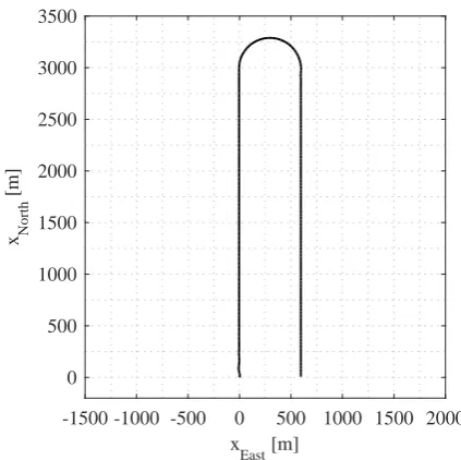
Proof of the proposed concept is performed via Monte Carlo sim-ulation study in several different situations. To make the simula-tions realistic, errors are introduced to all the a-priori information available to the navigation system, such as initial values of states, dynamic model parameters, and error statistics of IMU and GNSS measurements. Also, real 3D wind velocity data (KNMI and Al-terra, 2012) is used in simulations. Results of Monte Carlo sim-ulations on two sample trajectories are presented and analyzed in this paper, one for block imaging and the other for corridor map-ping. The reference trajectories for block imaging and corridor mapping are depicted in Figure 3 and Figure 4, respectively.
-200 0 200 400 600 800 1000
x East [m] -200
0 200 400 600 800 1000
x North
[m]
Figure 3: Block imaging trajectory
The Monte Carlo simulation on each trajectory consists of100 individual runs with different realizations of random errors in sensor data, initialization, and VDM parameters. Table 1 sum-marizes the results of attitude determination for both trajectories. The attitude errors are calculated based on taking the root mean square (RMS) of errors for all the 100 runs, which is then aver-aged over the whole trajectory. The numbers on top in each cell show the values for absolute attitude errors, while the numbers in parenthesis show the values for relative ones. The time step between consecutive images for relative attitude calculations is considered to be2s. In order to get more realistic results and get closer to real application scenarios in case of block imaging, the data on “turning parts” of trajectory are excluded from averaging
-1500 -1000 -500 0 500 1000 1500 2000 x
East [m] 0
500 1000 1500 2000 2500 3000 3500
x North
[m]
Figure 4: Corridor mapping trajectory
process as the optical instrument would not be used during such maneuvers. Also, a short part at the beginning of each of the two trajectories is omitted as it is predominately influenced by initial-ization errors and yet unstable gain within the filter. There are a number of interesting facts that can be concluded from the results in Table 1, some of which are discussed in the rest of this section.
Mean error [deg] absolute (relative)
Roll Pitch Yaw
Block imaging:
INS/GNSS 0.026 (0.039)
0.026 (0.039)
0.047 (0.017)
VDM/INS/GNSS 0.003 (0.006)
0.019 (0.006)
0.026 (0.013) Corridor mapping:
INS/GNSS 0.026 (0.039)
0.026 (0.039)
0.146 (0.037)
VDM/INS/GNSS 0.003 (0.004)
0.021 (0.007)
0.034 (0.013)
Table 1: Mean error in attitude determination
First thing to notice here is the improvement in attitude estima-tion provided by VDM/INS/GNSS integraestima-tion compared to con-ventional INS/GNSS. Table 2 reveals error reductions in percent-ages. The combined effect of roll and pitch errors, which is cal-culated as the norm of the two (p(roll error)2+ (
pitch error)2 ), has been reduced by 47%and41% for absolute case in block imaging and corridor mapping, respectively. At the flight altitude of150m, the ground error in DiSO due to this combined effect is equivalently reduced from9.6cmto5.1cmfor block imag-ing, and from9.6cmto5.6cmfor corridor mapping. The error reduction for yaw has been45%and77%for block imaging and corridor mapping, respectively.
For relative attitude determination, the error reduction in com-bined roll and pitch effect is almost two times greater, being85% for both trajectories. For yaw on the other hand, the error reduc-tion is less in both cases, namely22%for block imaging and66% for corridor mapping.
Block imaging absolute (relative)
Corridor mapping absolute (relative)
Roll 87 (85) 88 (91)
Pitch 27 (85) 19 (81)
Roll+Pitch 47 (85) 41 (85)
Yaw 45 (22) 77 (66)
Table 2: Percentage of improvement in attitude determination by VDM/INS/GNSS integration compared to INS/GNSS
is lack of enough maneuvers and trajectory dynamic, which di-minishes the opportunity of correcting yaw based on GNSS ob-servations within the navigation filter. For conventional INS/GNSS integration, yaw error for corridor mapping is 3.1 times bigger than block imaging, while this ratio is only1.3for VDM/INS/GNSS, which reveals much less sensitivity to maneu-vers in yaw estimation accuracy. This can be especially important for DiSO, since any error on yaw directly degrades the accuracy of final ortho-photos. For roll and pitch, both INS/GNSS and VDM/INS/GNSS methods show little or no sensitivity to maneu-vers.
In ISO, provided that there is sufficient forward overlap between consecutive images and there is enough texture visible in images, image measurements can control pitch and yaw errors to a good extent. Therefore, in applications where there is low side over-lap, such as corridor mapping, the most important contribution of aerial attitude control is in roll angle (Rehak and Skaloud, 2015). The proposed VDM/INS/GNSS integration has reduced the roll error8.2times for absolute and10.8times for relative approach in corridor mapping.
Finally, for both integration methods and for both trajectories, the real value of relative attitude estimation becomes evident in esti-mation of yaw with2to3.9times improvements. However, one should notice that in real implementation, the relative approach is capable of removing camera-to-IMU boresight, therefore further improvement in all the three attitude parameters may be expected compared to simulated results in this paper.
5. CONCLUSION AND PERSPECTIVES A novel method to perform autonomous navigation and sensor in-tegration for UAVs was recently introduced by the authors. This method is based on integrating vehicle dynamic model within navigation system, and has been already proven to be very effec-tive in reducing navigation solution drift during GNSS outages. In current paper, the application of this method for photogramme-try applications has been investigated, estimating attitude param-eters, while considering the availability of high accuracy GNSS positioning in two trajectories, one for block imaging and another for corridor mapping.
Results of100realizations in a Monte Carlo simulation showed considerable error reductions for both absolute and relative at-titude determination and for both trajectories. For example, at flight altitude of150mand in case of absolute attitude determina-tion, the improved attitude determination through VDM/INS/GNSS integration would reduce the ground error in DiSO due to combined effect of roll and pitch errors from9.6cm
to5.1cmfor block imaging, and from9.6cmto5.6cmfor cor-ridor mapping. This reduction was almost two times more for roll and pitch in case of relative attitude estimation, but less for yaw.
In conventional INS/GNSS integration, yaw determination is highly sensitive to maneuvers and trajectory dynamic in hori-zontal plane, as it needs enough dynamic to become observable
within the navigation filter. For the two trajectories in this paper, the error in yaw estimation by INS/GNSS was3.1times more for corridor mapping compared to block imaging. Such sensitivity is noticeably less for VDM/INS/GNSS, with the same ratio being only1.3, which can be considered as an important advantage of this method, especially for DiSO.
Based on simulation results in this paper, the benefit of relative at-titude estimation compared to absolute atat-titude estimation is more evident for yaw. This holds for both conventional and proposed integration methods, and for both trajectories. However, further improvements are expected from relative approach for all EO pa-rameters in real implementation, since it is capable of removing camera-to-IMU boresight, uncertainty of which is not included in simulations within this paper.
Further development of current work will include studies on pro-posed navigation system in real scenarios. Technical and per-haps scientific challenges can be expected in real implementation. Proper time stamping of all sensor observations and scaling the control input signals are examples of technical challenges. On the scientific part, the main challenges will probably be related to unmodeled dynamics and disturbances, and the inclusion of addi-tional effects, such as sensor misalignments, actuator dynamics, UAV body elasticity, and asymmetric mass distribution.
REFERENCES
Bl´azquez, M., 2008. A new approach to spatio-temporal calibra-tion of multi-sensor systems. The International Archives of the Photogrammetry, Remote Sensing and Spatial Information Sci-ences37, pp. 481–486.
Colomina, I. and Molina, P., 2014. Unmanned aerial systems for photogrammetry and remote sensing: A review. ISPRS Journal of Photogrammetry & Remote Sensing92, pp. 79–97.
Cook, M. V., 2013. Flight dynamics principles a linear sys-tems approach to aircraft stability and control. Butterworth-Heinemann, Waltham, MA.
Ducard, G. J., 2009. Fault-tolerant flight control and guidance systems: Practical methods for small unmanned aerial vehicles. Springer, London.
Gelb, A. (ed.), 1974. Applied optimal estimation. M.I.T. Press, Cambridge, Massachusetts, London.
Khaghani, M. and Skaloud, J., 2016. Autonomous Vehicle Dy-namic Model Based Navigation for Small UAVs.NAVIGATION, Journal of the Institute of Navigation (In Print).
KNMI and Alterra, 2012. Data provided by KNMI and Alterra, under the Consortium agreement on Cabauw Experimental Site for Atmospheric Research (CESAR), www.cesar-database.nl.
Rehak, M. and Skaloud, J., 2015. Fixed-wing micro aerial ve-hicle for accurate corridor mapping. ISPRS Annals of the Pho-togrammetry, Remote Sensing and Spatial Information Sciences
II-1/W1, pp. 23–31.
Rehak, M., Mabillard, R. and Skaloud, J., 2013. A micro-UAV with the capability of direct georeferencing. The International Archives of the Photogrammetry, Remote Sensing and Spatial In-formation Sciencespp. 317–323.