TRAJECTORY-BASED REGISTRATION OF 3D LIDAR POINT CLOUDS ACQUIRED
WITH A MOBILE MAPPING SYSTEM
Adrien Gressin, Bertrand Cannelle, Cl´ement Mallet, Jean-Pierre Papelard
IGN, MATIS, 73 avenue de Paris, 94160 Saint-Mand´e, FRANCE; Universit´e Paris-Est (firstname.lastname)@ign.fr
Commission III - WG III/2
KEY WORDS:point cloud, mobile mapping, registration, ICP, eigenvalues, dimensionality, neighborhood
ABSTRACT:
Thanks to a hybrid georeferencing unit coupling GNSS and IMU sensors, mobile mapping systems (MMS) with lidar sensors provide accurate 3D point clouds of the acquired areas, mainly urban cities. When dealing with several acquisitions of the same area with the same device, differences in the range of several tens of centimeters can be observed. Such degradation of the georeferencing accuracies are due to two main reasons: inertial drift and losses of GNSS signals in urban corridors. The purpose of this paper is therefore to correct these differences with an accurate ICP-based registration algorithm, and then to correct the MMS trajectory using these retrieved local transformation parameters.The trajectory loop information plays a key role for that purpose. We propose a four-step method starting from a 3D point cloud with overlapping parts, and the trajectory of the mobile mapping system. First, a polygonal approximation of the trajectory is computed in order to first divide the whole registration problem in local sub-issues. Secondly, we aim to find all the potential overlapping acquired areas between these segments using simple bounding box intersections. Thirdly, for each pair of overlapping areas, an efficient variant of the ICP algorithm is proposed to (1) prune cases where segments do not share point clouds of the same areas and (2) retrieve the transformation parameters, for real overlapping cases. Finally, all these transformations are linked together, and fed into a global distance compensation problem, allowing to adjust the MMS trajectories for several passages. As a conclusion, this method is successfully applied to data acquired over Paris (France) with the Stereopolis mobile mapping system.
1 INTRODUCTION
Cartography has been evolving for several decades following in-formatics tools developments. Nowadays, 3D models have be-come common place in diverse application areas such as naviga-tion, tourism, heritage, infrastructure monitoring or urban plan-ing. Many Mobile Mapping Systems (MMS) were developed to provide accurate 3D point clouds and high-resolution images mainly from urban cities. Those systems allow the creation and the update of very fine 3D models by coupling lidar system and HD digital cameras. Moreover, aerial data are simultaneously used in order to refine 3D models reconstruction (Frueh and Za-khor, 2004) and provide more realistic models.
Mobile Mapping Systems use hybrid georeferencing unit cou-pling GNSS, odometer and IMU (Inertial Measurement Unit) sen-sors in order to determine a precise position of the lidar sensen-sors and cameras (Grinstead et al., 2006). Due to urban corridors, GNSS signals losses are quite frequent, degrading the quality of the compensated trajectory. So that, with several acquisitions of the same area, differences in the range of several tens cen-timeters can be observed, which does not allow accurate appli-cations as metrology or change detection. An analysis of such errors is proposed in (Ellum and El-Sheimy, 2002). Neverthe-less, this problem is not as complex as Multi-View Stereo (Frahm et al., 2010), where most of the time no georeferencing data are available. Since, overlapping areas may exist within datasets, (Clemente et al., 2007) introduce loop information in order to im-prove the MMS trajectory estimation. Such a redundancy allows to compute accurate registration between two point clouds of the same overlapping area. Moreover, the ICP algorithm provides a robust and accurate registration of two coarse-aligned point clouds (Chen and Medioni, 1992). Many variants of this algo-rithm have been propose (Rusinkiewicz and Levoy, 2001). This registration step can be for instance improved using geometrical features proposed in (Demantk´e et al., 2011).
Therefore, the aim of this paper is to propose a correction strat-egy of georeferencing inaccuracies that may appear after the ac-quisition process with Mobile Mapping System. The method is purely based on the analysis of 3D point cloud acquired with a single lidar device. Trajectory loop information and overlapping areas are used to compute local transformations, which are fed into a global distance compensation problem, thus allowing to adjust the MMS trajectory. After introducing the MMS trajec-tory estimation, the four-step method is developed in Section 3 as follows : polygonal approximation of the trajectory, research of overlapping areas, registration of each of these areas and global minimization of the trajectory. The dataset is presented in Sec-tion 4. Finally, results of the method are presented in SecSec-tion 5, and conclusions are drawn in Section 6.
2 MOBILE MAPPING TRAJECTORY ESTIMATION 2.1 Estimation
Various on-the-fly systems, like GPSVan from Center of Map-ping at the Ohio State University (Novak, 1991), GEOMOBIL from ICC (Alam´us et al., 2005), Cyclomedia (Swart et al., 2011), Stereopolis from IGN (Paparoditis, 2011) have been developed mainly for street mapping applications. In these systems, the tra-jectory is estimated thanks to the direct georeferencing technol-ogy. Satellite positioning and inertial navigation information are provided by GNSS and IMU, respectively.
An odometer is traditionally added to provide vehicle body ve-locities and minimize the errors during GNSS signal losses. Fi-nally, the trajectory is optimally estimated with a Kalman Filter, that compensates the GNSS/IMU system errors (Abuhadrous et al., 2003). Several solutions, based on more or less complicated mathematical models exist, depending on the quality of the IMU. For more details, please see (El Sheimy, 2000).
However, the IMU drift and the GNSS signal losses are such that differences are still visible after the compensation step (Figure 1).
2.2 Improvement
Many solutions have been proposed to improve the quality of the estimated MMS trajectory. As mentioned above, the first solu-tion consists in improving the mathematical model introduced in the Kalman Filter (KF) solution. Such strategy assumes that both typical and large errors are well known, which is, in practice, not straightforward to have. The KF solution can be improved with the introduction of additional sensors or constraints. For exam-ple, new IMUs or GNSS antennas can be added, and coupled in a cascaded strategy (Cazzaniga et al., 2007). A coarse 3D model is introduced in (Lothe et al., 2009) for real-time applications. Finally, other methods directly rely on the acquired data. Con-sequently, both photogrammetric and lidar-based solutions are possible. Firstly, data resulting from Structure-from-Motion and dense matching are often used. Tardif et al. (2008) have noted that large field-of view cameras should be preferred to reduce the tra-jectory drift. Secondly, unlike photogrammetric techniques, lidar solutions are often not based on redundant measurements. Cal-ibration is for example performed using planar patches detected of the 3D point clouds. Howard et al. (2004) propose a three-step approach in order to compute trajectory. Firstly, a ”Fine-Scale” localization step use IMU and a ”scan matching” point cloud registration method in order to compute accurate segment of trajectory. Then, they perform a ”Coarse-Scale” localization step of each previously computed segment using GNSS. Finally, ”Coarse-to-Fine” localization aims to compensate the whole tra-jectory. Feature matching are introduced in this last step.
Figure 1: Georeferencing errors between two point clouds (red and blue color). The two trajectories are also visible. Shift can be noticed on cars and buildings facades.
3 IMPROVING TRAJECTORY ESTIMATION 3.1 Proposed strategy
Overlapping point clouds can indeed to locally registered to re-duce the existing shifts. The retrieved transformations allow to
introduce new constraints in the estimation procedure, and there-fore may benefit to areas that have been only acquired once. The four steps are as follows:
• Polygonal approximation: The trajectory is fragmented in segments in order to subsequently perform piecewise regis-tration;
• Overlapping area detection: Segments corresponding to the same geographical areas are matched;
• Registration: Pairs of segments (i.e., point clouds) are reg-istered. An improved ICP method is proposed for that pur-pose.
• Global trajectory estimation: Local transformations are fed into a global minimization procedure.
3.2 Polygonal approximation
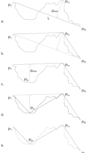
In order to fragment the initial trajectory in a reduce number of segments, the method described in (Lowe, 1987) is used. A set of points is recursively cut into segments with respect to both their length and deviation. Here, the points correspond to the recon-structed trajectoryi.e., the estimated MMS positions. Since the KF procedure is mastered by the georeferencing device with the highest acquisition rate, one position is available for each IMU measurement (100 Hz). This iterative algorithm consists of the following steps, illustrated in Figure 2.
For a set of points{P1, ..., PN}, the segmentl=P1PNis firstly
considered. The farthest trajectory point from this segment is considered (Figure 2a).
Figure 2: Illustration of the polygonal segmentation.
im= argmax
i∈[1,N]d(l, Pi), (1)
whered(l, Pi)is the orthogonal distance between the segmentl
This maximum distance is noteddm=d(l, Pim). Then, a
qual-ity criterionΨof the approximation of the set{P1, ..., PN}by
the linelis defined by:
Ψ({P1, ..., PN}) =
d(P1, PN)
dm
. (2)
Furthermore, the same method can be computed on the subset {P1, ..., Pim}and{Pim, ..., PN}(Figure 2c). This allows to
de-In order to determine if the sub-segmentation is better than the initial one, one can check whether:
max(Ψ1,Ψ2)> α∗Ψ0, (4)
whereαis an adjustment coefficient that defines the level of gen-eralization. If this inequality is true, pointPimis conserved, and
the process is recursively applied on the two sub-segments. Oth-erwise, segmentlis conserved. Finally, the polygonal approx-imation can be defined by a subset of points of the trajectory {Pa1, ..., PaM}wherea1= 1andaM =N.
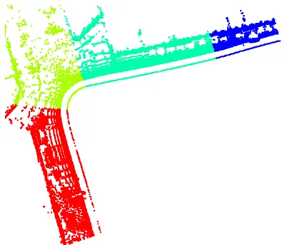
Similarly and subsequently to the trajectory, the lidar point cloud can be segmented. Since each 3D point is associated to a MMS position during the KF procedure, the partition is straightforward. It is noted :{S1, ..., SM−1}(cf.Figure 3).
Figure 3: Result of polygonal segmentation and the associated partition of the lidar point cloud over an area of interest (one color per segment, top view). One can note that all the segments do not have the same length.
3.3 Overlapping area detection
In order to register areas acquired several times, overlapping parts have to be found within the dataset. A first coarse approximation can be provided by the use of axis-aligned minimum bounding box. The result is then improved using point-to-point distance.
Approximation Firstly, the bounding boxBnof each lidar
sub-setSn is computed. Then, for a given subsetSi, non-empty
intersections with all previous bounding boxes of the trajectory (Sj, i < j−ǫ) are computed, resulting in the setΩ:
Ω ={(i, j)∈[1, M−1]2, i <(j−ǫ), Bi∩Bj6=∅}. (5)
Theǫparameter allows to avoid pairs of consecutive segments. It is simply set to 2 in our method.
The following step then consists in merging segment pairs as
(Si1, Sj),(Si2, Sj), whenSi1andSi2are consecutive segments
A new set of pairsΩf is therefore obtained. Such procedure
al-lows to avoid keeping several consecutive small segments in or-der to perform robust registration.
Refinement For a given pair of lidar point sets(A, B) ∈Ωf,
matching points betweenAandBare retrieved. Such matching points are retrieved using simple nearest neighbor query. The number of corresponding matching points with a relatively small distance (around the point cloud resolution) is notedN(A, B). Finally, only pairs(A, B)whereN(A, B) > T are conserved, resulting in the setΩr. Tis set to100in order to achieve robust
results in the following registration step.
3.4 Registration
This step consists in registering each pair of lidar point sets. In the literature, the most commonly adopted solution is the well-know ICP (Iterative Closest Point) algorithm (Chen and Medioni, 1992; Besl and McKay, 1992). This is a robust method that has been in-cremented with many variants (Rusinkiewicz and Levoy, 2001). This standard approach performs a fine registration of two over-lapping point clouds by iteratively estimating the transformation parameters, assuming that a gooda priorialignment is provided. In case of datasets acquired with a MMS equipped with GNSS and IMU, such condition is fulfilled. Furthermore, this algorithm can be easily improved and speed up using features of interest (Sharp et al., 2002) and (Bae and Lichti, 2008). We follow this strategy, and introduce in the ICP procedure the geometrical fea-tures proposed in (Gressin et al., 2012).
Features of interest Many neighborhood descriptors exist in the literature (Sharp et al., 2002) and (Rabbani et al., 2007). De-mantk´e et al. (2011) have proposed a multi-scale method that use geometric features computed from the local covariance matrix in order to retrieve the optimal radius neighborhood of each point. For a given radiusrand his associate neighborhoodVr, a
princi-pal component analysis give three eigenvalues(λ1, λ2, λ3). The standard deviation along an eigenvectori is denoted byσi = p
λj. Then, three geometrical features are introduced in order to
describe the linear (a1D), planar (a2D) or scattered (a3D)
behav-The dimensionality labeling (1D, 2D, or 3D) ofVr
can be defined
the dimensionality labelingd∗
(Vr)
results to 1. Conversely, if
σ1, σ2 ≫ σ3, a2Dprevails. Finally, σ1 ≃ σ2 ≃ σ3 implies
d∗(
Vr) = 3. One example of dimensionality labeling is
pre-sented in Figure 4. Dimensionality features are computed for in-creasing radius values between a lower boundrminto an upper
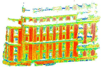
Figure 4: Dimensionality labeling for a building facade (Blue: 1D; Green: 2D; Red: 3D).
pointP, a measure of unpredictability is given by the Shannon entropy of the discrete probability distribution(a1D, a2D, a3D):
Ef(Vr) =−a1Dln(a1D)−a2Dln(a2D)−a3Dln(a3D). (8)
Then, the optimal neighborhood radiusr∗
is selected so as to minimize the entropy feature (cf. Figure 5).
r∗
P = argmin r∈[rmin,rmax]
Ef(Vr). (9)
The optimal neighborhoodV∗
, associated tor∗
is then used to compute the dimensionality labelingd∗
(Vr∗
P ). The moreEf, the
more prominent the retrieved local geometrical behaviour.
Figure 5: EntropyEf, ranging from 0 (blue) to 1 (red).
Local registration The four steps of the ICP algorithm are: (1) selecting a reduced number of points, (2) finding matching points, (3) weighting each corresponding pair, and, finally, (4) designing and minimizing a given error metric. Using geometric features can improve several steps of this method. According to (Gressin et al., 2012), the selection and the rejection steps can be enhanced as follows.
Firstly, a selection of points with a high entropy valueEf (more
than0.7) can better the convergence speed of a factor of two while maintaining an accuracy of one tenth of the point cloud resolution. This corresponds to points with a clear local promi-nent behaviour,i.e. in urban areas, building facades (cf. Figure 5).
Then, rejecting70%of the farthest matched points using a spe-cific distance improves the registration accuracy to a few millime-ter (depending on the point cloud resolution). The following dis-tancedV(P1, P2) =kVP1 − VP2khas been introduced, where
V =Q i
σiis proportional to the ellipsoid volume, and allows to
characterize the shape of the 3D point neighborhood.
Finally, this algorithm is applied to each pair of subset point
clouds(Si, Sj) ∈ Ωr. This step provides two information for
each couple:
1. A transformation(TICP
Si,Sj), which allows to register the two
overlapping point clouds;
2. An indicator of the quality of the procedure(σICPSi,Sj),
pro-viding by the average distance of matched points after reg-istration.
The first one will be used for the next stage of global minimiza-tion.
3.5 Global compensation
The two previous steps linked overlapping areas. The aim is now to compute the trajectory with more constrains in order to im-prove its accuracy as well as the 3D point cloud accuracy. Be-cause the positional system data (IMU, GNSS, odometer) are some times not available, our method only necessitates the 3D georeferencing position of the lidar scanner in order to obtain two different types of constraints (absolute and relative position-ing constraints).
Since the rotation resulting of the registration is very low, only translation-based minimization has been formulated and applied. Furthermore, introducing rotation in the minimization step results in loosing the linearity of the problem.
Let{Pa1, ..., PaM}be an approximation of the trajectory
{P1, ..., PM}of the mobile mapping system. Let{TaICPi,aj}be a
set of transformation given by the previous steps. The equations that the solution{P∗
ai}must satisfy are :
• Absolute positioning constraint :
∀i∈[1, M], P∗
ai=Pai (10)
• Relative positioning constraint :
∀i∈[1, M], P∗
ai−P
∗
a(i−1)=Pai−Pa(i−1) (11)
• Registration constraint :
∀(i, j)∈Ωr, Pa∗i−P
∗
aj =Pai−Paj+T ICP ai,aj (12)
This over constrained and linear problem can be solved using a standard least squares method. Furthermore, different weighting can be applied for the different equations. Indeed, the accuracy of the various positioning devices have different orders of mag-nitude. Whereas GNSS have typically an absolute accuracy of a few meter, the IMU and the odometer can give a relative accu-racy of a few centimeter, and the ICP gives a relative accuaccu-racy of a few millimeter. So weights ranging in the same proportions are introduced.
Finally, the transformation retrieves for each point of the approx-imate trajectory is linearly distributed on all the points of the tra-jectory, and transferred to the corresponding lidar points.
4 DATASET
includes5millions of points. The acquisition procedure of this dataset is based on a RIEGL LMSQ-120 lidar sensor which pro-vides vertical profiles perpendicular to the platform trajectory. The distance range of the system is from 2 to 150 meters with an accuracy of 20 mm. The lidar acquisition frequency is up to 30 kHz. The RIEGL sensor allows a vertical coverage of 40 deg with an angular resolution of 0.04 deg, using a rotating polygon mirror. Positioned vertically, the lidar sensor allows to acquire both the roads, the sidewalks and medium-sized buildings. How-ever, the tops of highest building may not be visible, depending on the distance from the sensor to the building. This configura-tion allows to cover areas with several interesting objects (street furniture), but also included many moving objects as pedestrian or cars. Using geometrical features permits to discard such items from the ICP procedure. The positional system coupling two GPS and one Applanix IMU POSVL200. The GPS acquire position at 1Hz, when the IMU have a frequency rate of 100Hz. This IMU has a drift of 3 deg/hr, resulting an accuracy of about 20 cm for a GPS signals looses of 1 minute (2 m for 3 minutes).
5 RESULTS
An upside view of this area can be seen in Figure 6 (left). Fig-ure 6 (right) shows the polygonal approximation of the trajectory. This polyline is composed of about 550 segments. This num-ber of segment, directly depend on the choice of theα parame-ter (Section 3.2). In this case, the valueα = 0.5is chosen in order to have enough segments, allowing a good approximation of the trajectory. This value also permits to not have too small segment that not allow to perform accurate registration. After
1
2
3 4 5
6 ✲ ✛ 100m
Figure 6: Trajectory fragmentation. Left: raw data, colored with respect to the distance from the MMS (low (black)→high (white)). Right: extracted polyline, colored with respect to the acquisition time (blue→red).
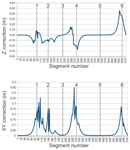
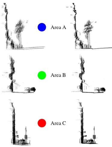
the refinement procedure, the second step provides 20 potential overlapping areas. All these selected areas have then success-fully registrated using our modified ICP algorithm. The global compensation method delivers an adjusted trajectory. This cor-rection ranges from -30 cm to 50 cm for the vertical component (Figure 7). The planimetric correction ranges from 0 to 45 cm. Peaks visible on the graph (1, 2, 4, 6) correspond to the overlap-ping areas, where ICP constrains are applied. Contrariwise, not compensated areas (3, 5) correspond to the area without redun-dancy. Finally, this correction is propagated to the 3D lidar point cloud (Figure 8). Figure 9 illustrates the results of the procedure for three areas of interests. In these areas, significant elevation differences are visible on the input data. These degradations are correctly rectified by our method. One can see that the trajectory-based correction of the georeferencing process is satisfactory and is not limited to areas with multiple surveys.
6 CONCLUSION
The objective of this paper was to propose a method for correct-ing georeferenccorrect-ing inaccuracies that may appear after the lidar
Figure 7: Results of the global compensation procedure. Areas of interest are indicated in Figure 6
A ⑥
B ⑥
C ⑥
✲ ✛ 100m
Figure 8: Registration results, colored with respect to the distance from the MMS. Three areas of interest (A,B,C) are detailed on Figure 9.
acquisition process with a Mobile Mapping System in a urban environment. The strategy was based on the trajectory loop in-formation and used areas acquired several times to find the lo-cal transformations, afterwards applied to the whole area. The only mandatory input is the trajectory estimated with a standard Kalman filter. The strategy did not require as input any measure-ment provided by the GNSS, the IMU or the odometer.
Area A ⑥
Area B ⑥
Area C ⑥
Figure 9: Results of our approach for three areas of interest. Left: before registration. Right: after registration.
are now available, offering the opportunity of processing point clouds with higher densities and quality or opening the field of change and mobile object detection.
As the ICP algorithm can also provide a rotation term, improve-ment may focus on introducing an orientation term in the global compensation step. Moreover, since most of Mobile Mapping Systems also include digital cameras with HD (panoramic) im-ages, an approach integrating both photogrammetric and lidar-based constraints is conceivable. For instance, Cannelle et al. (2009) proposed an image-based method that allows to adjust the MMS trajectory. These position data could be merged with those from our method in order to improve the reliability of the final compensation. Eventually, another possibility is to directly use, in the compensation step, raw data from the georeferencing unit that contains, as for the registration step, uncertainty information.
References
Abuhadrous, I., Nashashibi, F., Laurgeau, C. and Chinchole, M., 2003. Multi-sensor data fusion for land vehicle localization using RTMAPS. In: Proc. Intelligent Vehicles Symposium, IEEE, Columbus, USA, pp. 339–344.
Alam´us, R., Baron, A., Casacuberta, J., Pla, M., S´anchez, S., Serra, A. and Talaya, J., 2005. Geom`obil: ICC land based mobile mapping system for cartographic data capture. In: Proc. International Cartographic Conference, A Coru˜na, Spain, pp. 235–242.
Bae, K. and Lichti, D., 2008. A method for automated registration of unorganised point clouds. ISPRS Journal of Photogramme-try and Remote Sensing 63(1), pp. 36–54.
Besl, P. and McKay, N. D., 1992. A method for registration of 3D shapes. IEEE Trans. on PAMI 14(2), pp. 239–256.
Cannelle, B., Craciun, D., Paparoditis, N. and Boldo, D., 2009. Bundle adjustement and pose estimation of images of a multi-frame panoramic camera. In: Proc. Optical 3D Measurement Techniques, Vienna, Austria.
Cazzaniga, N., Forlani, G. and Roncella, R., 2007. Improving the reliability of a GPS/INS navigation solution for MM vehicles by photogrammetry. International Archives of Photogramme-try, Remote Sensing and Spatial Information Sciences 36 (Part I-5/C55), pp. 86–91.
Chen, Y. and Medioni, G., 1992. Object modelling by registra-tion of multiple range images. Image Vision Computing 10(3), pp. 145–155.
Clemente, L., Davison, A., Reid, I., Neira, J. and Tardos, J., 2007. Mapping large loops with a single hand-held camera. In: Proc. of RSS, Atlanta, USA.
Demantk´e, J., Mallet, C., David, N. and Vallet, B., 2011. Dimen-sionality based scale selection in 3D lidar point cloud. The In-ternational Archives of the Photogrammetry, Remote Sensing and Spatial Information Sciences 38 (Part 5/W12), (on CD-ROM).
El Sheimy, N., 2000. Inertial navigation and ins/gps integra-tion. Department of Geomeatics Engineering, University of Calgary, Canada.
Ellum, C. and El-Sheimy, N., 2002. Land-based mobile map-ping systems. Photogrametric Engineering & Remote Sensing 68(1), pp. 13–28.
Frahm, J., Pollefeys, M., Lazebnik, S., Gallup, D., Clipp, B., Raguram, R., Wu, C., Zach, C. and Johnson, T., 2010. Fast robust large-scale mapping from video and internet photo col-lections. ISPRS Journal of Photogrammetry and Remote Sens-ing 65(6), pp. 538–549.
Frueh, C. and Zakhor, A., 2004. An automated method for large-scale, ground-based city model acquisition. International Jour-nal of Computer Vision 60(1), pp. 5–24.
Gressin, A., Mallet, C. and David, N., 2012. Improving 3d lidar point cloud registration using optimal neighborhood knowl-edge. International Annals of Photogrammetry and Remote Sensing 40 (Part 3), (on CD-ROM).
Grinstead, B., Sukumar, S., Page, D., Koschan, A., Gorsich, D. and Abidi, M., 2006. Mobile scanning system for the fast dig-itization of existing roadways and structures. Sensor Review 26(4), pp. 283–289.
Howard, A., Wolf, D. and Sukhatme, G., 2004. Towards 3d map-ping in large urban environments. In: Proc. IROS, Vol. 1, Sendai, Japan, pp. 419–424.
Lothe, P., Bourgeois, S., Dekeyser, F., Royer, E. and Dhome, M., 2009. Towards geographical referencing of monocular slam reconstruction using 3d city models: Application to real-time accurate vision-based localization. In: Proc. of CVPR, Miami, USA.
Lowe, D., 1987. Three-dimensional object recognition from single two-dimensional images. Artificial Intelligence 31(3), pp. 355–395.
Novak, K., 1991. The Ohio State University Highway Mapping System: The stereo vision system component. In: Proc. of the 47th Annual Meeting of The Institute of Navigation, Williams-burg, USA, pp. 121–124.
Paparoditis, N., 2011. 3D data acquisition for 3D city modeling. In: Turkish National Society of Photogrammetry and Remote Sensing Symposium, Antalya, Turkey.
Rabbani, T., Dijkman, S., van den Heuvel, F. and Vosselman, G., 2007. An integrated approach for modelling and global registration of point clouds. ISPRS Journal of Photogrammetry and Remote Sensing 61(6), pp. 355–370.
Rusinkiewicz, S. and Levoy, M., 2001. Efficient variants of the ICP algorithm. In: Proc. 3DIM, Qu´ebec, Canada.
Sharp, G., Lee, S. and D.K., W., 2002. Icp registration using invariant features. IEEE Trans. on PAMI 24(1), pp. 90–102.
Swart, A., Broere, J., Veltkamp, R. and Tan, R., 2011. Refined non-rigid registration of a panoramic image sequence to a lidar point cloud. Photogrammetric Image Analysis pp. 73–84.