USING LEDs, LCDs
AND GLCDs IN
USING LEDs, LCDs
AND GLCDs IN
MICROCONTROLLER
PROJECTS
Dogan Ibrahim
Registered office
John Wiley & Sons Ltd, The Atrium, Southern Gate, Chichester, West Sussex, PO19 8SQ, United Kingdom For details of our global editorial offices, for customer services and for information about how to apply for permission to reuse the copyright material in this book please see our website at www.wiley.com.
The right of the author to be identified as the author of this work has been asserted in accordance with the Copyright, Designs and Patents Act 1988.
All rights reserved. No part of this publication may be reproduced, stored in a retrieval system, or transmitted, in any form or by any means, electronic, mechanical, photocopying, recording or otherwise, except as permitted by the UK Copyright, Designs and Patents Act 1988, without the prior permission of the publisher.
Wiley also publishes its books in a variety of electronic formats. Some content that appears in print may not be available in electronic books.
Designations used by companies to distinguish their products are often claimed as trademarks. All brand names and product names used in this book are trade names, service marks, trademarks or registered trademarks of their respective owners. The publisher is not associated with any product or vendor mentioned in this book. This publication is designed to provide accurate and authoritative information in regard to the subject matter covered. It is sold on the understanding that the publisher is not engaged in rendering professional services. If professional advice or other expert assistance is required, the services of a competent professional should be sought.
Library of Congress Cataloging-in-Publication Data
Ibrahim, Dogan.
Using LEDs, LCDs, and GLCDs in microcontroller projects / Dogan Ibrahim. p. cm.
Includes bibliographical references and index. ISBN 978-1-119-94070-8 (cloth)
1. Information display systems. 2. Liquid crystal devices–Automatic control. 3. Light emitting diodes–Automatic control. 4. Microcontrollers. I. Title.
TK7882.I6I185 2012 629.8’9–dc23
2012009481 A catalogue record for this book is available from the British Library.
Print ISBN: 9781119940708
Preface xiii
Acknowledgements xv
1 Introduction to Microcontrollers and Display Systems 1
1.1 Microcontrollers and Microprocessors 2
1.2 Evolution of the Microcontroller 3
1.3 Parts of a Microcontroller 4
1.3.1 Address 4
1.3.2 ALU 5
1.3.3 Analogue Comparator 5
1.3.4 Analogue-to-Digital Converter 5
1.3.5 Brown-out Detector 5
1.3.6 Bus 5
1.3.7 CAN 6
1.3.8 CISC 6
1.3.9 Clock 6
1.3.10 CPU 6
1.3.11 EEPROM 6
1.3.12 EPROM 6
1.3.13 Ethernet 7
1.3.14 Flash Memory 7
1.3.15 Harvard Architecture 7
1.3.16 Idle Mode 7
1.3.17 Interrupts 7
1.3.18 LCD Drivers 8
1.3.19 Pipelining 8
1.3.20 Power-on Reset 8
1.3.21 PROM 8
1.3.22 RAM 8
1.3.23 Real-time Clock 8
1.3.24 Register 9
1.3.25 Reset 9
1.3.26 RISC 9
1.3.28 Serial Input-Output 9
2.2.9 Special Features of the CPU 48
2.2.10 Interrupts 49
2.2.11 Pulse Width Modulator Module 53
2.3 Summary 56
Exercises 56
3 C Programming Language 59
3.1 C Languages for Microcontrollers 59
3.2 Your First mikroC Pro for PIC Program 61
3.2.1 Comments 61
3.2.2 Beginning and Ending a Program 62
3.2.3 White Spaces 63
3.2.10 Accessing Bits of a Variable 69
3.2.11 sbit Type 70
3.2.13 Arrays 70
3.2.14 Pointers 73
3.2.15 Structures 76
3.2.16 Unions 80
3.2.17 Operators in mikroC Pro for PIC 80
3.2.18 The Flow of Control 90
3.3 Functions in mikroC Pro for PIC 101
3.3.1 Function Prototypes 102
3.3.2 void Functions 103
3.3.3 Passing Parameters to Functions 104
3.3.4 Passing Arrays to Functions 106
3.3.5 Interrupt Processing 106
3.4 mikroC Pro for PIC Built-in Functions 108
3.5 mikroC Pro for PIC Libraries 109
3.5.1 ANSI C Library 109
3.5.2 Miscellaneous Library 111
3.6 Using the mikroC Pro for PIC Compiler 111
3.6.1 mikroC Pro for PIC IDE 112
3.6.2 Creating a New Source File 118
3.6.3 Compiling the Source File 122
3.7 Using the mikroC Pro for PIC Simulator 123
3.7.1 Setting a Break-Point 124
3.8 Other mikroC Pro for PIC Features 126
3.8.1 View Statistics 126
4 PIC Microcontroller Development Tools – Including Display
Development Tools 131
4.1 PIC Hardware Development Boards 132
4.1.1 Super Bundle Development Kit 132
4.1.2 PIC18 Explorer Board 132
4.1.3 PIC18F4XK20 Starter Kit 134
4.1.4 PICDEM 4 135
4.1.5 PIC16F887 Development Kit 135
4.1.6 FUTURLEC PIC18F4550 Development Board 137
4.1.7 EasyPIC6 Development Board 137
4.1.8 EasyPIC7 Development Board 139
4.2 PIC Microcontroller Display Development Tools 140
4.2.1 Display Hardware Tools 140
4.3 Using the In-Circuit Debugger with the EasyPIC7 Development Board 145
4.4 Summary 149
Exercises 149
5 Light Emitting Diodes (LEDs) 151
5.1 A Typical LED 151
5.10 mikroC Pro for PIC 7-Segment LED Editor 163
5.11 Summary 163
Exercises 164
6 Liquid Crystal Displays (LCDs) and mikroC Pro for PIC LCD Functions 165
6.1 HD44780 Controller 165
6.2 Displaying User Defined Data 168
6.3 DDRAM Addresses 169
6.4 Display Timing and Control 171
6.4.1 Clear Display 172
6.4.2 Return Cursor to Home 172
6.4.3 Cursor Move Direction 172
6.4.4 Display ON/OFF 172
6.4.5 Cursor and Display Shift 173
6.4.6 Function Set 173
6.4.7 Set CGRAM Address 173
6.4.8 Set DDRAM Address 173
6.4.9 Read Busy Flag 174
6.4.10 Write Data to CGRAM or DDRAM 174
6.4.11 Read Data from CGRAM or DDRAM 174
6.5 LCD Initialisation 174
6.5.1 8-bit Mode Initialisation 175
6.5.2 4-bit Mode Initialisation 175
6.6 Example LCD Display Setup Program 177
6.7 mikroC Pro for PIC LCD Functions 180
6.7.1 Lcd_Init 180
6.7.2 Lcd_Out 181
6.7.3 Lcd_Out_Cp 181
6.7.5 Lcd_Chr_Cp 181
6.7.6 Lcd_Cmd 182
6.8 Summary 182
Exercises 183
7 Graphics LCD Displays (GLCD) 185
7.1 The 12864 Pixel GLCD 185
7.2 Operation of the GLCD Display 187
7.3 mikroC Pro for PIC GLCD Library Functions 189
7.3.1 Glcd_Init 189
7.5 mikroC Pro for PIC Bitmap Editor 198
7.6 Adding Touch-screen to GLCDs 199
7.6.1 Types of Touch-screen Displays 200
7.6.2 Resistive Touch Screens 200
7.7 Summary 203
Exercises 204
8 Microcontroller Program Development 205
8.1 Using the Program Description Language and Flowcharts 205
8.1.1 BEGIN – END 206
8.1.3 IF – THEN – ELSE – ENDIF 206
8.3 Representing for Loops in Flowcharts 216
8.4 Summary 218
Exercises 218
9 LED Based Projects 219
9.1 PROJECT 9.1 – Flashing LED 219
9.2 PROJECT 9.2 – Binary Counting Up LEDs 226
9.3 PROJECT 9.3 – Rotating LEDs 229
9.4 PROJECT 9.4 – Wheel of Lucky Day 231
9.5 PROJECT 9.5 – Random Flashing LEDs 239
9.6 PROJECT 9.6 – LED Dice 240
9.7 PROJECT 9.7 – Connecting more than one LED to a Port Pin 246
9.8 PROJECT 9.8 – Changing the Brightness of LEDs 250
9.9 PROJECT 9.9 – LED Candle 264
9.10 Summary 267
Exercises 267
10 7-Segment LED Display Based Projects 269
10.1 PROJECT 10.1 – Single Digit Up Counting 7-Segment LED Display 269 10.2 PROJECT 10.2 – Display a Number on 2-Digit 7-Segment LED Display 271 10.3 PROJECT 10.3 – Display Lottery Numbers on 2-Digit 7-Segment LED
Display 278
10.4 PROJECT 10.4 – Event Counter Using 4-Digit 7-Segment LED Display 285 10.5 PROJECT 10.5 – External Interrupt Based Event Counter Using 4-Digit
7-Segment LED Display with Serial Driver 292
10.6 Summary 302
Exercises 303
11 Text Based LCD Projects 305
11.1 PROJECT 11.1 – Displaying Text on LCD 305
11.2 PROJECT 11.2 – Moving Text on LCD 307
11.3 PROJECT 11.3 – Counting with the LCD 310
11.4 PROJECT 11.4 – Creating Custom Fonts on the LCD 315
11.5 PROJECT 11.5 – LCD Dice 317
11.6 PROJECT 11.6 – Digital Voltmeter 325
11.7 PROJECT 11.7 – Temperature and Pressure Display 327
11.8 PROJECT 11.8 – The High/Low Game 333
11.9 Summary 344
12 Graphics LCD Projects 347
12.1 PROJECT 12.1 – Creating and Displaying a Bitmap Image 347
12.2 PROJECT 12.2 – Moving Ball Animation 355
12.3 PROJECT 12.3 – GLCD Dice 357
12.4 PROJECT 12.4 – GLCD X-Y Plotting 372
12.5 PROJECT 12.5 – Plotting Temperature Variation on the GLCD 374
12.6 PROJECT 12.6 – Temperature and Relative Humidity Measurement 385
12.7 Operation of the SHT11 386
12.8 Acknowledgement 389
12.9 Summary 400
Exercises 400
13 Touch Screen Graphics LCD Projects 401
13.1 PROJECT 13.1 – Touch Screen LED ON-OFF 401
13.2 PROJECT 13.2 – LED Flashing with Variable Rate 410
13.3 Summary 418
Exercises 418
14 Using the Visual GLCD Software in GLCD Projects 419
14.1 PROJECT 14.1 – Toggle LED 420
14.2 PROJECT 14.2 – Toggle more than One LED 425
14.3 PROJECT 14.3 – Mini Electronic Organ 426
14.4 PROJECT 14.4 – Using the SmartGLCD 430
14.5 PROJECT 14.5 – Decimal to Hexadecimal Converter using the SmartGLCD 444
14.6 Summary 452
Exercises 452
15 Using the Visual TFT Software in Graphics Projects 453
15.1 PROJECT 15.1 – Countdown Timer 454
15.2 PROJECT 15.2 – Electronic Book 462
15.3 PROJECT 15.3 – Picture Show 467
15.4 Summary 472
Exercises 472
Bibliography 473
A microcontroller is a single chip microprocessor system, which contains data and program memory, serial and parallel I/O, timers, and external and internal interrupts, all integrated into a single chip that can be purchased for as little as £2.00. About 40% of microcontroller applications are in office automation, such as PCs, laser printers, fax machines, intelligent telephones, and so on. About one-third of microcontrollers are found in consumer electronic goods. Products such as CD players, hi-fi equipment, video games, washing machines, cook-ers and so on fall into this category. The communications market, automotive market and the military share the rest of the application areas.
Input and output are very important parts of any microcontroller system. Typical input devices are push-button switches, keypads and various analog and digital sensors. Typical output devices are Light Emitting Diodes (LEDs), Liquid Crystal Displays (LCDs), Graphics Liquid Crystal Displays (GLCDs), motors, actuators, buzzers, and so on. This book is about the theory and applications of display devices in microcontroller based systems. The book explains briefly the theory of the commonly used display devices, namely LEDs, 7-Segment LED displays, LCDs, monochrome GLCDs and TFT based colour LCDs. In addition, the use of each display device is explained with several working and tested projects. The description, block diagram, circuit diagram, operation and full program code of all the projects are given. PIC18F series of high-end microcontrollers are used in all the projects. The projects are developed using the highly popular mikroC Pro for PIC compiler. Knowledge of the C programming language will be useful. Also, familiarity with at least one member of the PIC16F series of microcontrollers will be an advantage. The knowledge of assembly language programming is not required because all the projects in the book are based on using the C language.
This book is written for students, for practising engineers and for hobbyists interested in developing display based projects using the PIC series of microcontrollers.
Chapter 1 presents the basic features of microcontrollers and the basic features of display devices used in such systems.
Chapter 2 provides a review of the PIC18 series of microcontrollers. Various features of these microcontrollers are described in detail. The PIC18F2410 is chosen as a typical microcontroller.
Chapter 3 provides a short tutorial on the C language and then examines the features of the mikroC Pro for PIC compiler used in PIC series of microcontrollers.
Chapter 5 provides the basic theory of LEDs. The use of simple LEDs and 7-Segment simple and multiplexed LEDs are explained with examples.
Chapter 6 provides some simple projects using the PIC18 series of microcontrollers and the mikroC Pro for PIC C language compiler. All the projects in this chapter are based on the PIC18F452 microcontroller and all the projects have been tested and are working. This chapter should be useful for those who are new to PIC microcontrollers, and for those who want to extend their knowledge of programming PIC18F series of microcontrollers using the mikroC Pro for PIC language.
Chapter 7 covers the theory of LCD displays. The basic working principles of LCDs and the mikroC Pro for PIC built-in LCD functions are explained with several examples.
Chapter 8 is about the Program Development Language (PDL) used to describe the opera-tion of software in general. Various building blocks of the PDL are described in this chapter.
Chapter 9 provides simple LED based projects, ranging from LED flashing to more com-plex LED projects.
Chapter 10 is about 7-Segment LED based projects. Several single digit and multiplexed working and tested projects are given in this chapter with full source code.
Chapter 11 provides several text based LCD projects. The use of LCDs is described in this chapter through simple and complex projects, ranging from displaying simple text on an LCD to developing an LCD based voltmeter project.
Chapter 12 is about the use of GLCDs in microcontroller projects. The use of standard monochromatic 12864 pixel GLCD is used in the projects in this chapter.
Touch screen displays are important application areas of microcontrollers. Chapter 13 gives several projects on using touch screens in graphics applications.
The Visual GLCD software package is used for the development of projects based on sev-eral different types of monochromatic GLCD displays. Chapter 14 explains the use of this software package and gives the steps required to develop GLCD based applications. Several projects are given in this chapter using the Visual GLCD software package with both 12864 pixel and 240128 pixel GLCD displays.
Finally, Chapter 15 is about the Visual TFT software package used for the development of TFT based colour graphics applications. The chapter describes the steps required to create microcontroller based TFT graphics applications using the MikroMMB graphics develop-ment board.
The following material is reproduced in this book with the kind permission of the respective copyright holders and may not be reprinted, or reproduced in any way, without their prior consent.
Figures 2.1–2.6, 2.10, 2.11, 2.13, 2.17, 2.28, 2.30, 2.32–2.37 are taken from Microchip Technology Inc. Data Sheet PIC18F2X1X/4X1X (DS39636D). Figures 4.2–4.4 are taken from the web site of Microchip Technology Inc.
Figure 4.1 is taken from the web site of microEngineering Labs Inc.
Figure 4.5 and 4.6 are taken from the web site of Custom Computer Services Inc. Figure 4.7 is taken from the web site of Futurlec Inc.
Figures 4.8 and 4.9 are taken from the web site of mikroElektronica.
1
Introduction to Microcontrollers
and Display Systems
The basic building blocks of any digital computer are the central processing unit (CPU), the memory and the input-output (I/O). The CPU is like the human brain, as it controls all inter-nal operations of the computer. Instructions are fetched from the memory under the control of the CPU, which it then decodes and controls various internal parts of the computer so that the required operations are performed. The CPU also includes an arithmetic and logic unit (ALU), which is used to perform mathematical and logical operations. The result of an oper-ation is stored either in the memory, in a temporary register, or is sent to an I/O port. Two types of memories are used in a computer, as far as memory functionality is concerned. The program memory stores the user instructions and this memory is normally non-volatile, that is the data is not lost after removal of the power. The second type of memory is the data memory, which stores the temporary user data, such as the result of an operation. The I/O ports allow the computer to communicate with the external world. For example, a keyboard is an input device, enabling the user to enter data to the computer. Similarly, a printer is an output device, enabling the user to print out a hard copy of data in paper form. Depending on the actual application and the requirements, a computer may include additional components, such as timers, counters, interrupt logic, clock logic, and so on.
A computer program consists of a collection of instructions for performing a specific task. In the early days of computers, programs were written in Assembly language, which was a short way of specifying instructions using words called mnemonics. Although Assembly lan-guage was fast, it had several disadvantages. Writing a long and complex program using Assembly language was difficult. More importantly, it was difficult to maintain a program written in Assembly language. Also, different processors had different instruction sets and different Assembly language instructions, resulting in no portability. Consequently, it was a tedious task to convert a program written for one processor to function on another processor. Over the last decade, nearly all programs have been written using a high level language such as C, BASIC or Pascal. High level languages have several advantages. First, learning to pro-gram in a high level language is easy. Second, the developed code is highly portable. For example, a C program written for a processor can easily be modified to work on another type
of processor. This is true, even if the two processors are manufactured by different vendors. Third, high level programs are much easier to develop and maintain.
1.1 Microcontrollers and Microprocessors
A microcontroller is basically a single chip computer, generally requiring no external com-ponents. A microprocessor differs from a microcontroller in many ways. Perhaps the main difference is that a microcontroller can function as a computer without the need of any exter-nal hardware. A microprocessor, on the other hand, is just the CPU of a computer, and requires several other external components before it becomes a useful computer. Because a microcontroller consists of a single chip, its power consumption is low. The development of a microcontroller based system is also easy, as the processing hardware consists of a single chip. Perhaps the only advantage of a microprocessor over a microcontroller is that a micro-processor can easily be expanded to have more memory or I/O. The expansion of microcon-trollers is more difficult and a different model is usually chosen when higher performance, more memory or more I/O are required.
Figure 1.1 shows the structure of a computer, built using a microprocessor. Here the hardware consists of several components, all attached to the microprocessor chip. The structure of a microcontroller based computer is shown in Figure 1.2. The advantages of using a microcontroller instead of a microprocessor are clear when Figures 1.1 and 1.2 are compared.
The differences between a microprocessor and a microcontroller are summarised below:
A microprocessor is a single chip CPU microcontroller containing a CPU, memory, I/O, timers, counters and much of the remaining circuitry of a complete computer system on a single chip.
The power consumption of a microprocessor based computer is very large, in the order of amperes. On the other hand, the power consumption of a microcontroller based computer is in the range of several hundred milliamperes. In addition, microcontrollers can be oper-ated in sleep modes, which consume currents as low as tens of nanoamperes.
A microprocessor based computer costs much more than a microcontroller based system.
Microprocessor Output
Because a microcontroller based system consists of a single chip, it has higher reliability. Microprocessor based systems can easily be expanded, for example by adding more
mem-ory or I/O chips. It is usually not possible to expand a microcontroller system. If an appli-cation requires more memory, more I/O or higher processing power, then a different model microcontroller is usually chosen.
Although microcontrollers have only been with us for a few decades, they have been used in many consumer, commercial, industrial and educational devices. Some examples are found in:
Offices: in typewriters, computers, calculators, photocopiers, scanners, plotters, elevators, and so on;
Homes: in microwave ovens, washing machines, alarm clocks, dish washers, hi-fi equip-ment, DVD players, digital televisions, and so on;
Industry: in automatic control systems, safety systems, robotics, motor control, and so on; Transportation systems: in vehicles, traffic signals, road signs, speed cameras, GPS
sys-tems, and so on;
Supermarkets: in weighing scales, cash registers, electronic signs, card readers, and so on; Play: in electronic toys, MP3 players, video games, mobile phones, and so on;
Education: in electronic white-boards, photocopiers, projectors, calculators, and so on.
1.2 Evolution of the Microcontroller
The first microprocessor, named the 4004, was introduced by the Intel Corporation in 1971. This was a simple 4-bit device, supported by three other chips to make a computer; the 4001 and 4002 memory chips, and the 4003 shift register. 4004 was initially used in calculators and in simple control applications.
Shortly after the 4004 appeared in the commercial marketplace, many electronic compa-nies realised the power and future prospects of microprocessors and so have heavily invested in this field. Three other general-purpose microprocessors were soon introduced: Rockwell International 4-bit PPS-4, Intel 8-bit 8008 and the National Semiconductor 16-bit IMP-16.
Microprocessor Output
These microprocessors were based on PMOS technology and can be classified as the first-generation devices.
In the early 1970s, we see the second-generation microprocessors in the marketplace, designed using the NMOS technology. The shift to NMOS technology resulted in higher execution speeds, as well as higher chip densities. During this time, we see 8-bit microproc-essors such as the Motorola 6800, Intel 8080 and 8085, the highly popular Zilog Z80, and Motorola 6800 and 6809.
The third generation of microprocessors were based on HMOS technology, which resulted in higher speeds and, more importantly, higher chip densities. During 1978, we see the 16-bit microprocessors such as the Intel 8086, Motorola 68 000 and Zilog Z8000. The 8086 micro-processor was so successful that it was used in early PC designs (called PC XT).
The fourth generation of microprocessors appeared around the 1980s and the technology was based on HCMOS. During this generation we see the introduction of 32-bit devices into the marketplace. Intel introduced the highly popular 32-bit microprocessors 80 386, 80 486, and the Pentium family; and Motorola introduced the 68 020 family. The Intel processors have been used heavily in early PC designs. In parallel to the development of 32-bit micro-processors, we see the introduction of early single chip computers (later named microcon-trollers) into the marketplace. The Intel 8048 was the first microcontroller, followed by the highly popular 8051 series. The 8051 device has been so popular that it is still in use today. This device was a true single chip computer, containing a CPU, data memory and erasable program memories, I/O module, timer/counter, interrupt logic, clock logic, and serial com-munications module, such as the Universal Synchronous Asynchronous Receiver Transmitter (USART). After the success of the 8051, we see many other companies offering microcon-trollers. Today, some of the most popular general-purpose low-cost 8-bit microcontrollers are Microchip PIC series, Atmel AVR series, Motorola HC11 series, and 8051 and its derivatives.
The fifth and the current generation of microcontrollers are now based on 16-bit and 32-bit architectures (e.g. PIC32 series). It is interesting to note that currently the 8-bit microcontrol-lers are still popular and much more in demand. This is because of their simple architectures, low cost, low power requirements, and the availability of the vast number of hardware and software development tools. The power offered by the high-end 8-bit microcontrollers (e.g. the PIC18F series) are enough for most medium to high-speed applications, except perhaps in special cases of digital signal processing where much higher throughput is generally required.
1.3 Parts of a Microcontroller
Before explaining microcontroller architectures and programming, it is worthwhile to look at the parts of a microcontroller in more detail and understand some basic terms.
1.3.1
Address
1.3.2
ALU
An arithmetic and logic unit (ALU) is part of a computer where the actual mathematical and logical operations are performed. 8-bit microcontrollers have 8-bit ALU modules. Typical operations carried out by an ALU are addition, subtraction, division, logical ANDing, ORing, Exclusive-OR and comparison. Some ALUs can also perform signed or unsigned multiplication.
1.3.3
Analogue Comparator
Some microcontrollers have built-in analogue comparator modules. An analogue compar-ator module is used to compare the voltage levels of two analogue signals. Although this feature is implemented in most mid-range PIC microcontrollers, it is not an important functionality.
1.3.4
Analogue-to-Digital Converter
Analogue-to-digital converter (A/D converter) is used to convert an analogue input signal into digital form, so that the signal can be processed within the microcontroller. Most mid-range PIC microcontrollers have built-in A/D converter modules. In general purpose and low-speed applications, the A/D converters are 8 to 10 bits, having 256 or 1024 quantisation levels. An A/D converter can either be unipolar or bipolar. Unipolar converters can only han-dle signals that are always positive. Bipolar converters, on the other hand, can hanhan-dle both positive and negative signals. The A/D converters implemented in PIC series of microcon-trollers are unipolar. The A/D conversion process is started by the user program and the conversion can take tens of processor cycles to complete. The user program has the option of either polling the conversion status and waiting until the conversion is complete, or alterna-tively, the A/D converter completion interrupt can be enabled to generate an interrupt as soon as the conversion is complete.
1.3.5
Brown-out Detector
Brown-out detectors in microcontrollers is a feature that can be configured to reset a micro-controller if the power supply voltage falls below a nominal value. The brown-out detector is a safety feature, as it protects the microcontroller data or the program from being corrupted while working below the recommended supply voltage.
1.3.6
Bus
1.3.7
CAN
CAN bus is used in the automotive industry. Some microcontrollers include CAN bus mod-ules, which simplify the design of CAN bus based products. For example, the PIC18F4680 provides CAN interface.
1.3.8
CISC
CISC is also known as the Complex Instruction Computer. In CISC architecture, both data and instructions are of the same width (e.g. 8-bits wide) and the microcontroller usually has over 200 instructions. Data and instructions are on the same bus and cannot be fetched at the same time.
1.3.9
Clock
A clock is basically a square wave signal used to provide timing signals to a digital proces-sor. A clock is generated either using external devices (e.g. crystal, resistor-capacitor etc.), or some microcontrollers have built-in clock generation circuits. The PIC18F microcontroller family can operate with clock frequencies of up to 40 MHz. The basic instruction cycle in a PIC microcontroller takes four clock cycles. Thus, the effective operating frequency, or the MIPS (Millions of Instructions per Second) value is equal to the clock frequency divided by four, that is 10 MIPS.
1.3.10
CPU
The central processing unit (CPU), is the brain of a computer system, administering all activ-ity in the system and performing all operations on data. The CPU consists of the ALU, sev-eral registers, and the control and synchronisation logic. The CPU fetches instructions from memory, decodes these instructions, and finally executes them. Decoding an instruction is the process of deciding what control signals to send to other internal parts of the computer for the successful execution of the instruction.
1.3.11
EEPROM
The electrically erasable programmable read only memory (EEPROM) is a non-volatile memory that can be erased and reprogrammed using a suitable programming device. EEPROMs are used in microcontroller based systems to store semi-permanent data, such as configuration data, maximum and minimum values, identification data, setup data, and so on. Most PIC microcontrollers have built-in EEPROM memories. One disadvantage of these memories is their much slower write times than their read times.
1.3.12
EPROM
can be erased under strong ultraviolet light in a few minutes. An EPROM is programmed by inserting the chip into a socket of an EPROM programmer device, which is connected to a PC. After programming the chip, the window can be covered with dark tape to prevent acci-dental erasure of the data, for example under direct sunlight. An EPROM must be erased before it can be re-programmed. EPROM memories are commonly used during the program development time where the programs keep changing until finalised. Some versions of EPROMs are known as One Time Programmable (OTP), which can be programmed only once but cannot be erased.
1.3.13
Ethernet
The Ethernet interface enables a microcontroller to be connected to a local area network, and in addition provides Ethernet interface capabilities. A microcontroller with such an interface can be connected to the Internet and can send and receive TCP/IP based packets. Some microcontrollers, such as the PIC18F97J60, have built-in Ethernet capabilities.
1.3.14
Flash Memory
Flash memory is a non-volatile memory used mainly to store user programs. This type of memory can be programmed electrically while embedded on the board. Some microcontrol-lers have only 1 KB flash memory, while some others can have 32 KB or more. In addition to computers, flash memory is also used in mobile phones and digital cameras.
1.3.15
Harvard Architecture
This is a type of CPU where the program memory and data memory units and buses are separate. The result is that the processor can fetch instructions and data at the same time, thus increasing the performance. Several microcontrollers, including the PIC family, are designed using the Harvard architecture.
1.3.16
Idle Mode
This mode is similar to the sleep mode and is used to conserve power. In idle mode, the internal oscillator is off but the peripheral devices are on.
1.3.17
Interrupts
execute the code just before the interrupt occurred. The ISR is usually at a fixed address of the program memory, known as the interrupt vector address. Some microcontrollers have priority based interrupt sources, with different interrupt vector addresses for different sources.
1.3.18
LCD Drivers
Some microcontrollers offer LCD drivers and interface signals, so that standard LCD modules can be directly connected. Since all of the LCD functions can be implemented in software, such microcontrollers are not popular.
1.3.19
Pipelining
Pipelining is a technique used in computer systems to overlap the instruction fetch time with execution time. This allows higher throughput as two operations are performed in parallel. In microcontrollers, pipelining is generally used to fetch the next instruction while executing the current instruction. PIC microcontrollers use two-stage pipelining to speed up the execu-tion time.
1.3.20
Power-on Reset
The power-on reset circuit keeps the microcontroller in the reset state until all the internal circuitry has been initialised. This is important, as it places the microcontroller clock into a known state. The power-on reset can be enabled or disabled during programming of PIC microcontrollers.
1.3.21
PROM
Programmable read only memory (PROM) is a non-volatile memory similar to a ROM. But PROM can be programmed by the end user with the aid of a PROM programmer device. PROM can only be programmed once and its contents cannot be changed after programming the device.
1.3.22
RAM
Random access memory (RAM) is a general purpose read-write memory used to store tem-porary data in a program. RAM is a volatile memory where the stored data is cleared after the power is turned off. All microcontrollers have some amount of RAM. Some may have only a few hundred bytes, while others can have up to 4 KB or more.
1.3.23
Real-time Clock
1.3.24
Register
A register is a volatile, temporary high-speed storage for data. All microcontrollers have some amount of registers. Some microcontrollers, such as the PIC family, have a Special Function Register (SFR), used to hold the configuration data for various functions of the microcontrol-ler. For example, the I/O direction registers hold the direction of each I/O pin. Similarly, the PORT registers hold the data received from a port, or data to be sent to an I/O port.
1.3.25
Reset
All microcontrollers have reset facilities. A reset action can be automatic by software (e.g. when the watchdog is enabled but not refreshed), or an external button can be used to reset the microcontroller. Reset puts the microcontroller into a known state. Usually, after a reset, the program starting from memory address 0 of the microcontroller is executed.
1.3.26
RISC
In a Reduced Instruction Set Computer (RISC) microcontroller, the data and instructions are not usually of the same width. For example, in an 8-bit RISC microcontroller, the data is 8-bits but the instructions can be 12, 14 or 16 bits wide. RISC microcontrollers have a lim-ited number of instructions (e.g. not more than 50).
1.3.27
ROM
Read only memory (ROM) is non-volatile and is used to store user programs. A ROM is normally programmed in the factory during the manufacturing process. ROM is not re-programmable and its contents cannot be erased. ROM is normally used when a program has been tested and is working correctly, and it is desired to make thousands of copies of the same program.
1.3.28
Serial Input-Output
Serial ports on a microcontroller enable communication using the RS232 protocol. For example, the microcontroller can be connected to a PC via its serial port and then data can be exchanged between the microcontroller and the PC. Although serial communication can be implemented in software, most microcontrollers have built-in USART modules to read and write serial data through its ports. Most mid-range PIC microcontrollers are equipped with at least one USART module.
1.3.29
Sleep Mode
1.3.30
Supply Voltage
Most microcontrollers operate with the standard logic voltage ofþ5 V. The range of accept-able voltage is usually in the rangeþ4.75 toþ5.25 V. The manufacturers’ data sheets usually give the acceptable power supply voltage limits. PIC18F microcontrollers can operate with a power supply ofþ2 toþ5.5 V. The required power supply voltage is usually obtained using a regulated power supply. In portable applications, theþ5 V supply is obtained using aþ9 V battery with aþ5 V regulator chip (e.g. 78L05).
1.3.31
Timers
Timers are used in timing and counting applications. Most microcontrollers are equipped with at least one, and in many cases, several timers. A timer is usually 8 or 16 bits wide. Data is loaded into the timer under program control. The timer counts up at each clock pulse (or every time an external event occurs), and when the timer overflows an interrupt is gener-ated (if interrupts are enabled). One common application of timers is to generate delays in programs, or to schedule events at regular intervals.
1.3.32
USB
USB is a powerful high-speed communications port used to connect various devices together. Some microcontrollers include built-in USB modules, which simplify the USB based com-munications. For example, the PIC18F250 microcontroller has a built-in USB module.
1.3.33
Watchdog
A watchdog is basically a programmable timer circuit that can be refreshed by the user pro-gram. It is usually used in real-time, and time based applications where time critical modules of a program are used to refresh the watchdog. If the watchdog fails to be refreshed, this is a sign that a time critical module has not completed its task. An automatic software reset occurs if the watchdog is enabled but is not refreshed. The watchdog is a safety feature, used to detect loops and runaway code in programs.
1.4 Display Devices
Display devices are output devices that can be connected to I/O ports of microcontrollers. Most electronic equipment, whether consumer related, commercial or industrial, have some form of display device, for example, mobile phones, calculators, GPS systems, printers, computers, MP3 players, microwave ovens, and so on.
In this section we are only concerned with small display devices commonly used in micro-controller based projects. In general, we can divide these display devices into three groups: LED based, OLED based and LCD based.
1.4.1
LED
example, the on/off status of an electronic device, the selection of an item, and so on. Simple LEDs are available in various colours, such as red, green, orange, blue and white, and are directly connected to I/O ports of microcontrollers via current limiting resistors.
1.4.2
7-Segment LED
7-segment LEDs (see Figure 1.4) are generally used to display numeric data. The numbers are made up of 7 segments and the required number is displayed by turning on or off the appropriate segments. There are two types of 7-segment displays: common-anode or common-cathode. In common-anode displays, the anode pin is connected to the supply voltage and the individual segments are turned on by grounding the required segment. In a common-cathode type display, the cathode is connected to ground and the individual seg-ments are turned on by applying voltage to the required segment. Both types can easily be connected and driven from a microcontroller I/O pin. To display numbers between 0 and 9, a single digit is used. To display higher numbers, it is necessary to use multiple digits (see Figure 1.5). In multi-digit applications, each digit is turned on or off by controlling its
Figure 1.3 Simple LEDs
common pin. The digits are enabled and disabled alternately, and very fast in such a way that when viewed the user thinks that the display is stationary.
1.4.3
OLED
Organic Light Emitting Diode (OLED) displays can be used to display text as well as graphi-cal images. These displays are constructed by inserting organic material between a pair of electrodes where at least one of the electrodes is transparent. When an electric current is applied to the two conductors, a bright, electro-luminescent light is produced from the organic material. There are two types of OLEDs, as far as the used material is concerned: those based on small molecules and those employing polymers. OLED displays work with-out a backlight and thus they can be used both with-outdoors and indoors in low ambient light conditions.
OLEDs have several advantages compared to other displays:
OLEDs have wide viewing angles and improved brightness. The pixel colours appear cor-rect, even as the viewing angle approaches vertical from normal.
OLED displays have very fast response times, more than 200 times faster than LCDs. OLED displays can be fabricated on flexible substrates, with the possibility of making
roll-up displays embedded in fabrics.
OLED displays produce sharp and bright pictures.
Extremely thin and lightweight OLED displays can be constructed. The power consumption of OLED displays is extremely low. OLEDs have some disadvantages compared to other displays:
Manufacturing of OLED displays is costly.
OLED displays have limited lifespans, usually 14 000 hours (corresponding to 5 years at 8 hours a day usage).
OLED displays can be damaged by water and therefore tight sealing is required, which increases the cost.
OLED displays suffer from screen burn-in problems, where pixels fade after displaying the same content for a long time.
OLED displays can be damaged by exposure to UV light. As a result, OLED displays cannot be used in countries where the UV is very high. Manufacturers usually install UV blocking filters over the screen to protect the displays.
The material used to produce blue light degrades more rapidly than the materials used for other colours. As a result, the colour balance of the overall display changes, causing the colours to be wrongly displayed.
1.4.4
LCD
Segment LCD is also known as the alphanumeric LCD. These LCDs can display numbers represented by 7 segments, or numbers and Roman letters represented by 14 or 16 segments. In addition, symbols can also be displayed. The segment LCDs are limited to displaying numbers, text and symbols. If we need to display other characters or shapes, then either a dot matrix display or a graphic display should be used. Figure 1.6 shows a typical 16-segment LCD display.
Dot Matrix LCD is also known as the character LCD. The most commonly used dot matrix LCD displays are 2 lines of 16 characters. Each character is represented by 57 dots (or 58 characters including the cursor). Dot matrix LCDs can display alphanumeric data, including a subset of symbols. Figure 1.7 shows a typical dot matrix LCD display.
Graphic LCDs are composed of pixels and provide the greatest flexibility to the user. In a graphic LCD, pixels are arranged in rows and columns and each pixel can be addressed indi-vidually. Graphic LCDs are used when we need to display numbers, letters, symbols, shapes or pictures. Figure 1.8 shows a typical graphics LCD display.
LCD displays produce no light of their own and so require an external light source to be visible. On some displays, a cold cathode fluorescent lamp is inserted behind the LCD panel. On some other models, the ambient light is used to make the display visible.
Figure 1.7 Dot matrix LCD display Figure 1.6 16-segment LCD display
LCD displays use the light modulating properties of liquid crystals. In a standard LCD display, a layer of molecules are aligned between two transparent Tin Oxide electrodes and two polarising filters placed at right angles to each other, as shown in Figure 1.9. Ambient light enters the LCD through the front polarising filter. The light then passes through the liquid crystals, which rotate the light passing through them. This rotation is usually 90 degrees in most type of LCDs. In the OFF state, since the light is rotated, it passes through the second polarising filter. Applying a voltage across the electrodes (ON state) orients the liquid crystals so that they are parallel to the electric field and the twisted structure disap-pears. Thus, the light is no longer rotated and light passing through the second polariser in the crossed shape is absorbed, thus causing the activated portion of the display to appear dark.
LCD displays can be classified as Passive Matrix and Active Matrix, depending upon the pixel addressing scheme used. A pixel matrix is addressed by rows and columns. In a passive display, transistors are used to activate rows and columns, not each pixel. In an active dis-play, on the other hand, transistors are used at each red, green and blue pixel to keep the pixel at the desired intensity. In general, passive matrix displays are less costly and have narrower viewing angles than active matrix displays. Active matrix displays are sharper, have more contrast than passive displays, and also have faster response times.
There are many types of LCD displays, depending upon the amount and type of twisting used in liquid crystals. Some examples are: TN (Twisted Nematic 90
Twist), STN (Super-twisted Nematic 270
Twist), FSTN (Film Compensated STN), DSTN (Double Layer STN), and so on.
One of the LCD displays that has become popular recently is the (TFT (Thin Film Tran-sistor) LCD, used in most mobile phones, laptop monitors and desktop computer monitors. TFT is an active matrix display providing the best resolution of all the LCD types, but it is also the most expensive type. In a TFT display, the transistors are made from a thin film of amorphous silicon deposited on a glass panel. TFT displays offer excellent response times, and sharp and crisp images. Some TFT displays are incorporated with touch screen hard-ware panels that enable the user to make a selection by touching the appropriate places on the screen.
1.4.4.1 LCD Viewing Modes
Reflective: In this mode, LCDs use ambient light to illuminate the display and are therefore more suitable for outdoor use.
Transmissive: In this mode, LCDs use ambient light to illuminate the display and are therefore more suitable for indoor use.
Transflective: Transflective mode includes both reflective and transmissive types, so can be used both indoors and outdoors.
1.4.4.2 Key Specifications of LCDs
Resolution: Number of pixels, measured in horizontal and vertical (e.g. 1024768); View size: The diagonal size of the LCD display;
Dot pitch: The distance between two adjacent same colour pixels. The dot pitch is either specified as the number of dots per inch, or the distance is given in millimetres (e.g. 0.25 mm). The smaller the dot pitch size (or higher the number of dots per inch), the sharper the image becomes;
Response time: The minimum time it takes to change a pixel’s brightness (or colour). The response time is measured in milliseconds and typical values are several milliseconds. A low response time is always desirable;
View angle: The angle from which the LCD can be viewed without loss of any detail; Brightness: The amount of light emitted from the display;
Contrast ratio: The ratio of the luminance of the brightest colour (white) to that of the darkest colour (black). A high contrast ratio is a desirable feature of any display;
Aspect ratio: The ratio of the width of the LCD to its height (e.g. 16: 9, 4: 3, etc.)
1.5 Summary
This chapter has provided an introduction to the microcontroller and microprocessor based computer systems. The differences between the two types of computer systems have been explained in detail. In addition, some of the most commonly used concepts in microcontrol-lers have been described.
The final part of the chapter has provided an introduction to the display systems used in microcontroller based applications. An explanation of the important terms used in displays has also been given.
Exercises
1.1 What is a microprocessor?
1.2 What is a microcontroller? Explain the differences between a microprocessor and a microcontroller.
1.3 Where would you use a flash memory? 1.4 Where would you use RAM memory?
1.5 What is an A/D converter? Give an example for its use in a microcontroller based application.
1.7 What happens when a microcontroller is reset?
1.8 How many types of LCDs are there? Which one would you choose if the number of I/O ports is limited?
1.9 What is a graphics LCD? Give an example for its use in practise. 1.10 Explain the operation of passive and active display technologies.
1.11 What is a TFT display? Why are TFT displays popular? In which type of applications are they commonly used?
1.12 What is an OLED display? Explain its operation. What are the differences between a TFT and an OLED display?
2
PIC18F Microcontrollers
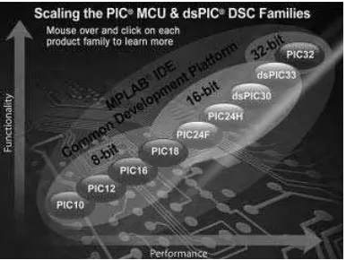
PIC is a family of Harvard architecture microcontrollers (except the 32-bit devices) manu-factured by Microchip Technology Inc. PIC microcontrollers are available in over 1000 mod-els. Depending upon the data width used, we can classify these microcontrollers in three groups: 8-bit, 16-bit and 32-bit microcontrollers. Figure 2.1 shows an overview of the PIC series of microcontrollers.
The PIC 10, 12, 16 series are the low-end 8-bit microcontrollers with low speed, low pin count, low cost, small memories, with only 35 instructions, making them easy to learn and program. PIC18 series are medium-end 8-bit microcontrollers with medium speed, higher pin count, large memories, and having over 80 instructions. These microcontrollers include various on-chip modules, such as CAN, USB, SPI, multiple USARTs, several timers, multi-plier hardware, and clock speeds up to 40 MHz. These microcontrollers are currently used in most new complex PIC microcontroller projects. PIC24 and dsPIC series are 16-bit high-speed microcontrollers with large memories and peripheral support, designed for time-critical applications where real-time processing is very important. These microcontrollers find applications in digital signal processing (DSP) and in high-speed automatic digital con-trol systems. The architectures of these 16-bit microconcon-trollers are different to the 8-bit microcontrollers, as they are configured for high-speed processing required in DSP applica-tions, having fast multiplication and addition modules (MACs).
The new PIC32 microcontroller family are 32-bit processors with standard Von Neumann architecture, having large memories and peripheral support, offering very high speed proc-essing in highly precision applications. One of the advantages of PIC microcontrollers is that they support easy migration across product families. For example, a project designed using a PIC16 series microcontroller can easily be upgraded to use a PIC18 series microcontroller. This is especially true if the development was carried out using a high-level language such as C, which is compatible across all the 8-bit families.
Currently, most medium-speed general purpose projects with graphical display require-ments are based on the PIC18F series, as they provide the required speed, large data and program memories, and large number of input-output capabilities.
PIC18 microcontrollers are available in many models, from small 18-pin chips to 100-pin chips, program memories from 4 KB to 128 KB, data memories from 256 bytes to 4 KB, and input-output pins from 15 to 70.
In this chapter we look in detail at the architecture of a medium-end PIC18 microcontrol-ler, namely the PIC18F2410, as it will be necessary to know the basic architecture of the PIC18 series of microcontrollers when we begin creating display based projects in later chapters. The reason for choosing the PIC18F2410 is because it is a low-cost, yet powerful microcontroller, having only 28 pins, and its architecture can be considered as representative of the PIC18F series.
2.1 The PIC18F2410 Microcontroller
The PIC18F2410 microcontroller belongs to the family PIC18F2X1X/4X1X. There are 8 microcontrollers in this family, with slightly different specifications. Table 2.1 gives the basic specifications of the microcontrollers in this family.
The basic features of the PIC18F2410 microcontroller are:
16 KB program memory; 768 bytes data memory;
Figure 2.1 PIC microcontroller series
Table 2.1 The PIX18F2X1X/4X1X microcontroller family
25 I/O pins;
each I/O pin has 25 mA source/sink capability; 10-bit 10 channel A/D converters;
18 interrupt sources; interrupt priority levels; 4 timers;
DC to 40 MHz operating frequency; capture/compare/PWM modules;
USART module;
master synchronous serial port module (MSSP); low-voltage detection module (LVD);
power-on reset (POR), power-up timer (PWRT), oscillator startup timer (OST); watchdog timer (WDT);
75 instructions (83 with extended instruction set enabled);
20 nA current consumption in sleep mode (CPU and peripherals off); 28-pin package.
2.2 PIC18F2410 Architecture
The pin configuration (DIP package) of the PIC18F2410 microcontroller is shown in Figure 2.2. As we shall see later, most of the pins are multiplexed and can be used for different purposes. For example, pin 2 is named as RA0/AN0 and this is the PORT A least significant port pin. This pin can be used as an analogue input (named AN0), or as a digital I/O (named RA0).
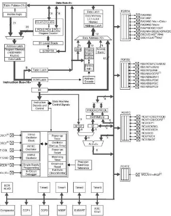
Figure 2.3 shows the simplified internal architecture of the PIC18F2410 microcontroller. The CPU is at the centre of the diagram and consists of an 8-bit ALU, an accumulator regis-ter (WREG), and an 88 multiplier module. The multiplier takes data from the accumulator register and the data bus, and provides the 16-bit result in registers PRODH and PRODL, where the result can be read through the data bus.
when an interrupt occurs. The stack is independent of the data memory and is addressed with a 5-bit stack pointer STKPTR. The stack pointer is initialised to 00 000 after a reset.
The data memory can be seen at the top right corner of the figure. The data addresses are 12 bits, thus up to 4 KB data can be addressed, although here only 768 bytes of data memory are implemented.
The instruction decode and control logic, located at the centre of the figure, decodes the instructions fetched from the program memory and sends the appropriate control signals to all parts of the microcontroller to implement the required operation.
Just below the instruction decode and control logic, we see the timing and power control module. This module is responsible for generating the clock timing pulses for both the exter-nal and interexter-nal clock. In addition, this module controls the power-on timer, oscillator startup, POR, watchdog timer, brown-out reset, single-supply programming, in-circuit debugger, and the fail safe clock monitoring.
At the bottom of the figure we can see the four timer modules, comparator/capture/pwm modules, master synchronous serial port module (MSSP), USART module, and the A/D con-verter module.
There are 4 I/O ports named PORTA, PORTB, PORTC and PORTE, and 25 I/O pins shown at the right side of the figure. PORTA, PORTB and PORTC are 8-bit ports, while PORTE has only 1 bit. All ports pins are bi-directional when configured as digital I/O.
2.2.1
The Program Memory
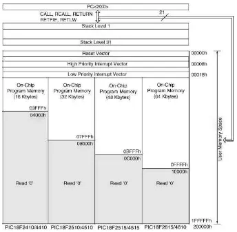
Figure 2.4 shows a memory map of the PIC18F2410 microcontroller. The device has a 21-bit program counter (PC<20: 0>), capable of addressing up to 2 MB of memory, although here only 16 KB is used, ranging from 00 000 h to 03 FFFh. Memory addresses above 0400 h are read as 0 and are not available. The Reset vector is at address 00 000 h and the program counter is loaded with this address after a reset, causing the program starting at this address to be executed. Addresses 00 008 h and 00 018 h are the high and low priority interrupt vec-tors, respectively. Thus, for example, when a low priority interrupt occurs, the program jumps to address 00 008 h.
An instruction cycle in an 8-bit PIC microcontroller consists of 4 cycles (Q1 to Q4). A fetch cycle begins with the program counter incrementing in Q1. The fetched instruction is decoded and executed in cycles Q2, Q3 and Q4. A data memory location is read during the Q2 cycle and written during the Q4 cycle. Because an instruction cycle consists of 4 cycles, the performance of a PIC microcontroller is measured by dividing the operating clock fre-quency by 4. For example, a processor operating with a 40 MHz clock frefre-quency has a MIPS (Million Instructions Per Second) rating of 10 MIPS.
2.2.2
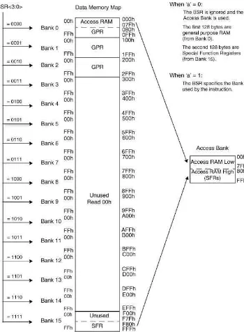
The Data Memory
of BANK 15 is reserved for the SFR (Special Function Registers) registers. SFR registers control internal modules of the microcontrollers, such as A/D converter, interrupts, timers, USART, I/O ports, and so on.
2.2.3
Power Supply Requirements
The PIC18F2410 microcontroller operates with a power supply of 4.2 to 5.5 V, at the full speed of 40 MHz. The low-power version of the microcontroller (PIC18LF2410) can operate at a voltage as low as 2.0 V. As shown in Figure 2.6, at low voltages the maximum operating frequency is limited. For example, at 2.0 V the maximum operating frequency should not exceed 4 MHz. In practical applications, most microcontrollers are operated with a supply of 5.0 V, derived using a 78L05/7805 or a similar voltage regulator.
2.2.4
Oscillator Configurations
The PIC18F2410 microcontroller can be operated in 10 different oscillator modes. The user can program the required oscillator mode during programming of the device. These modes are:
low-power crystal (LP); Crystal/Resonator (XT);
high-speed crystal/resonator with PLL enabled (HSPLL); external resistor-capacitor with Fosc/4 on OSC2 (RC); external resistor-capacitor with I/O on OSC2 (RCIO);
internal oscillator with Fosc/4 on OSC2 and I/O on OSC1 (INTIO1); internal oscillator with I/O on OSC2 and OSC1 (INTIO2);
external clock with Fosc/4 output on OSC2(EC); external clock with I/O on OSC2 (ECIO).
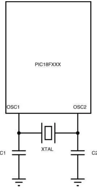
2.2.4.1 Using Crystal (LP/XT)
A crystal should be used in applications requiring high timing accuracies. The crystal is connected to pins OSC1 and OSC2 of the microcontroller with a pair of capacitors, as shown in Figure 2.7. That capacitor value depends on the oscillator mode and is shown in Table 2.2. In most applications, a 15–33 pF capacitor should be sufficient to achieve stability.
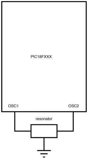
2.2.4.2 Using Resonator (XT)
A resonator should be used in low-cost applications where high timing accuracy is not essential. Resonators are available at low to medium frequencies, up to 10 MHz. The reso-nator should be connected to pins OSC1 and OSC2 of the microcontroller, as shown in Figure 2.8.
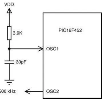
2.2.4.3 Using External Resistor-Capacitor (RC/RCIO)
Using an external resistor-capacitor (RC) for timing provides the cheapest solution. Here, the clock frequency depends on the chosen resistor and capacitor values, component tolerances,
Figure 2.7 Operation with a crystal
Table 2.2 Required capacitor values
Mode Frequency C1,C2 (pF)
LP 32 kHz 33
200 kHz 15
XT 200 kHz 22–68
1.0 MHz 15
4.0 MHz 15
HS 4.0 MHz 15
8.0 MHz 15–33
20.0 MHz 15–33
power supply, temperature, and ageing of components. The clock frequency is not accurate and can easily change from unit to unit due to component tolerances.
Table 2.3 gives the approximate clock frequency with different RC combinations. The resistor should be between 3 K and 100 K, and the capacitor should be greater than 20 pF.
Figure 2.8 Operation with a resonator
Table 2.3 Selecting a resistor and capacitor
C (pF) R (K) Frequency (MHz)
22 3.3 3.3
4.7 2.3
10.0 1.08
30 3.3 2.4
4.7 1.7
The clock frequency is given approximately by
f¼1=ð4:2 RCÞ ð2:1Þ
As an example, for a 2 MHz clock, we can choose a capacitor of 30 pF and a resistor of 3.9 K. Figure 2.9 shows the circuit diagram for RC mode operating at approximately 2 MHz. Notice that in RC mode, a clock is output from pin OSC2 with a frequency of Fosc/4, that is 500 Hz in this example.
The RCIO mode is similar to the RC mode, except that in RCIO mode the OSC2 pin is available as a general purpose I/O.
2.2.4.4 Using the Internal Oscillator (INTIO1/INTIO2)
An internal oscillator can be extremely useful in many applications. First, it eliminates the need to use an external timing device, thus reducing the cost and the component count. Sec-ond, by using an internal oscillator, the microcontroller oscillator pins become available for general purpose I/O.
PIC18F2410 includes two internal oscillators. A factory calibrated 8 MHz clock source (IINTOSC), and an RC based 31 kHz clock source (INTRC). In the INTIO1 mode, the OSC2 pin outputs a clock at frequency Fosc/4, while the OSC1 pin (RA7) can be used as general digital I/O. In the INTIO2 mode, both OSC1 and OSC2 pins function as general purpose I/O pins (RA6 and RA7).
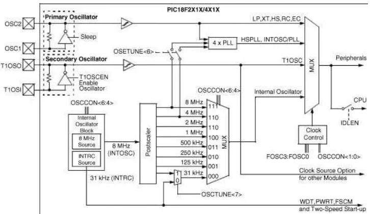
Although the 8 MHz clock source is factory calibrated, the frequency can drift slightly and the SFR register OSCTUNE can be used to re-calibrate this clock source (see manufacturers’ data sheet for more information). The 8 MHz clock drives a postscaler, and a multiplexer is used to provide clock frequencies in the range 31 kHz to 8 MHz.
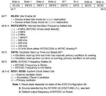
Figure 2.10 shows the internal structure of the clock selection mechanism. SFR register OSCCON controls the clock selection, as shown in Figure 2.11. For example, to select an 4 MHz internal clock, bits<6: 4>of OSSCON should be set to binary pattern ‘110’.
The PIC18F2410 microcontroller includes a feature that allows the device clock source to be switched from the main oscillator to an alternative lower frequency clock source for con-serving power. Essentially, there are two clock sources: Primary oscillator and Secondary oscillator. The primary oscillator includes the external crystal and resonator modes, external RC modes, and the internal oscillator. The Secondary oscillator is where Timer 1 is used as an internal oscillator.
2.2.4.5 Using External Clock (EC/ECIO)
In this mode of operation, an external clock source is connected to pin OSC1 of the micro-controller. In EC mode, pin OSC2 (RA6) provides a clock output at the frequency Fosc/4. In ECIO mode, pin OSC2 (RA6) is available as a general purpose I/O. Figure 2.12 shows oper-ation with an external clock.
2.2.4.6 High-speed Crystal/resonator with PLL (HSPLL)
High-speed operation is possible using the Phase Locked Loop (PPL) to multiply the selected clock source by 4. The PLL operation is available either with the external crystal/ resonator (HSPLL), or by using the internal clock.
In the HSPLL mode of operation, an external crystal or resonator is connected to the OSC1 and OSC2 pins, as in mode XT. The internal PLL of the microcontroller is then pro-grammed to multiply the clock frequency by 4 to provide higher frequencies. External crys-tal/resonator up to 10 MHz can be used in this mode, to provide an operating frequency of 40 MHz. Bits FOSC3:FOSC0 of the Configuration register 1H are used to set the HSPLL mode (see manufacturers’ data sheet for more information).
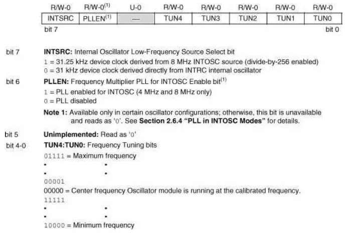
When used with the internal clock sources, the PLL can produce clock speeds of 16 MHz (with a 4 MHz internal clock) or 32 MHz (with an 8 MHz internal clock). The PLL for the internal clock sources is enabled by setting bit 6 of the SFR register OSCTUNE, as shown in Figure 2.13.
Figure 2.11 OSCCON register bit definitions. (Reproduced with permission from Microchip Inc)
2.2.5
The Reset
The Reset action puts the microcontroller into a known state, where the program counter is loaded with address 0 and program execution starts from this address. There are several actions that may cause a reset action:
Power-on Reset (POR);
MCLR Reset during normal operation; MCLR Reset during power-managed modes; Watchdog Timer (WDT) Reset;
Programmable Brown-out Reset (BOR); Reset instruction;
Stack full Reset; Stack underflow Reset.
In this section we are interested in the most commonly used reset actions: Power-on Reset and MCLR Reset during normal operation.
2.2.5.1 Power-on Reset
with a 1 K to 10 K resistor before the POR is enabled. Figure 2.14 shows a typical POR circuit, where the MCLR pin is connected to the supply voltage via a 10 K resistor. In appli-cations where the rise time of the supply voltage is small, it is recommended to use a diode and a capacitor in the POR circuit, as shown in Figure 2.15.
2.2.5.2 External Reset
In some applications we may want to force an external reset action, for example by pressing a button. This can easily be arranged by the circuit shown in Figure 2.16. The MCLR pin is normally at logic HIGH during normal operation. Pressing the button forces MCLR to be LOW, which causes a reset action.
2.2.6
Parallel I/O Ports
The PIC18F2410 microcontroller supports 4 I/O ports named PORT A, PORT B, PORTC and PORT E. The first three ports are 8-bits wide, while PORT E has only 1 bit. The bits of a
Figure 2.15 Power-on circuit for slow rising supply voltage
port are named as RPn, where P is the port name, and n is the bit number. For example, RB0 is bit 0 of PORT B. Similarly, RA7 is bit 7 of PORT A, and so on.
The I/O ports are bi-directional. An input port pin can easily be changed to become an output pin, and vice versa. Port pin directions must be configured before they are used. The SFR register TRIS is used to configure the port directions. Each port register has a corresponding TRIS register. Thus, for example, the TRIS register for PORT A is TRISA, the TRIS register for PORT B is TRISB, and so on. Clearing a bit in a TRIS register forces the corresponding port pin to become an output. Simi-larly, setting a bit in a TRIS register forces the corresponding port pin to become an input. For example, to configure pins 0, 1, 3 of PORT B to become output and the remaining pins to become input, we have to load the following values into the TRISB register:
7 6 5 4 3 2 1 0
1 1 1 1 0 1 0 0
TRISB = 0xF4;
In addition to the standard port registers, every port has a latch register. This register is called LATx, where x is the port name. For example, PORT A latch register is LATA, PORT B latch register is LATB, and so on. The latch register holds the actual value sent to a port pin. Thus, for example, when reading from a port pin, we have two choices. If we read from the latch register, then the value read is unaffected by any external device con-nected to the port pin. If, on the other hand, the port pin is pulled low (even though a logic HIGH was sent to the port) by an externl device, then reading the port register will give a HIGH value.
2.2.6.1 PORT A
PORT A is an 8-bits wide, parallel I/O port, with the pin configuration shown in Table 2.4. As shown, the port pins are multiplexed and can be used for different purposes. Most of the PORT A pins can be configured either as digital I/O or as analogue inputs. This port has the following registers associated with it:
PORTA register. TRISA register. LATA register.
Register PORTA is used to write and read data from the port pins. TRISA register is used to set the port pin directions. LATA is the latch register used to read a latched output value from the port.
Output: TRIS register is loaded with logic 0, thus the Q output of TRIS Latch is 0, ena-bling the output buffer to the I/O pin. If a data is now placed on the D input of the data latch, this data appears as the output of the port pin.
Input using port input: TRIS register is loaded with logic 1, thus the Q output of TRIS Latch is 1, disabling the output buffer to the I/O pin. To read data from the I/O pin, the RD Port pin is set to logic 1, thus enabling the input latch and placing the input data on the data bus.
Input using LATx register: TRIS register is loaded with logic 1, thus Q output of TRIS Latch is 1, disabling the output buffer to the I/O pin. Setting pin RD LAT to 1 reads the data
Table 2.4 PIC18F2410 microcontroller PORT A pin functions
Pin Description
VREF A/D reference voltage (low) input
CVREF Comparator reference output
RA3/AN3/VREFþ
RA3 Digital I/O
AN3 Analogue input 3
VREFþ A/D reference voltage (high) input
RA4/T0CKI/C1OUT
RA4 Digital I/O
T0CKI Timer 0 external clock input
at the output of the data latch and places it on the data bus. Remember that the data read here is the actual data sent to the port output earlier, and this data is not affected by any devices connected to the I/O pin.
On POR, PORT A pins RA5 and RA3:RA0 are configured as analogue inputs. Pin RA4 is configured as digital input. SFR register ADCON1 can be used to change the port config-uration. For example, setting ADCON1 to 07F configures all PORT A pins to become digital.
2.2.6.2 PORT B
PORT B is an 8-bit parallel port with the pin configuration shown in Table 2.5. As with PORT A, all the PORT B pins are multiplexed with other functions, such as analogue inputs and interrupt inputs.
As in PORT A, PORT B has the following registers associated with it:
PORTB register. TRISB register. LATB register.
On POR, PORT B pins RB4:RB0 are configured as analogue inputs and RB7:RB5 pins are configured as digital inputs. Configuration register PBADEN or SFR register ADCON1 can be programmed to change the PORT B pin configuration. For example, when PBADEN is set to 1, all pins with analogue functions are set to analogue input mode.
2.2.6.3 PORT C
PORT C is also an 8-bit bi-directional port with multiplexed pins. The pin configuration of PORT C is shown in Table 2.6. Most points of PORT C are multiplexed with timer, USART and SPI bus functions.
Table 2.5 PIC18F2410 microcontroller PORT B pin functions
Pin Description
RB0/INT0/FLT0/AN12
RB0 Digital I/O
INT0 External interrupt 0
FLT0 PWM fault input for CCP1
AN12 Analogue input 12
CCP2 Capture 2 input, Compare 2 and PWM2 output
RB4/KBIO/AN11
RB4 Digital I/O
KBIO1 Interrupt on change input
AN11 Analogue input 11
RB5/KBI1/PGM
RB5 Digital I/O, Interrupt on change pin
KBI1 Interrupt on change input
PGM Low voltage ICSP programming pin
RB6/KBI2/PGC
RB6 Digital I/O, Interrupt on change pin
KBI2 Interrupt on change input
PGC In-circuit debugger and ICSP programming pin
RB7/KBI3/PGD
RB7 Digital I/O, Interrupt on change pin
KBI3 Interrupt on change input
As in the other ports, PORT C has the following registers associated with it:
PORT C register. TRISC register. LATC register.
On power-on, all pins of PORT C are configured as digital inputs.
2.2.6.4 PORT E
On the PIC18F2410 microcontroller, PORT E is a single bit input only port, multiplexed with the MCLR (reset pin) and VPP (programming voltage pin) functions, and is available when
MCLRE¼0.
Table 2.6 PIC18F2410 microcontroller PORT C pin functions
Pin Description
RC0/T1OSO/T13CKI
RC0 Digital I/O
T1OSO Timer 1 oscillator output
T13CKI Timer 1/Timer 3 external clock input