ISBN: 0-8247-0732-X
This book is printed on acid-free paper.
Headquarters Marcel Dekker, Inc.
270 Madison Avenue, New York, NY 10016 tel: 212-696-9000; fax: 212-685-4540
Eastern Hemisphere Distribution Marcel Dekker AG
Hutgasse 4, Postfach 812, CH-4001 Basel, Switzerland tel: 41-61-261-8482; fax: 41-61-261-8896
World Wide Web http:==www.dekker.com
The publisher offers discounts on this book when ordered in bulk quantities. For more information, write to Special Sales=Professional Marketing at the headquarters address above.
Copyright#2002 by Marcel Dekker, Inc. All Rights Reserved.
Neither this book nor any part may be reproduced or transmitted in any form or by any means, electronic or mechanical, including photocopying, microfilming, and recording, or by any information storage and retrieval system, without permission in writing from the publisher.
Current printing (last digit): 10 9 8 7 6 5 4 3 2 1
1. Electron and Ion Microscopy and Microanalysis: Principles and Applications, Lawrence E. Murr
2. Acousto-Optic Signal Processing: Theory and Implementation, edited by Nor man J. Berg and John N. Lee
3. Electro-Optic and Acousto-Optic Scanning and Deflection, Milton Gottlieb, Clive L. M. Ireland, and John Martin Ley
4. Single-Mode Fiber Optics: Principles and Applications, Luc B. Jeunhomme 5. Pulse Code Formats for Fiber Optical Data Communication: Basic Principles and
Applications, David J. Morris
6. Optical Materials: An Introduction to Selection and Application, Solomon Musikant
7. Infrared Methods for Gaseous Measurements: Theory and Practice, edited by Joda Wormhoudt
8. Laser Beam Scanning: Opto-Mechanical Devices, Systems, and Data Storage Optics, edited by Gerald F. Marshall
9. Opto-Mechanical Systems Design, Paul R. Yoder, Jr.
10. Optical Fiber Splices and Connectors: Theory and Methods, Calvin M. Miller with Stephen C. Mettler and Ian A. White
11. Laser Spectroscopy and Its Applications, edited by Leon J. Radziemski, Richard W. Solarz, and Jeffrey A. Paisner
12. Infrared Optoelectronics: Devices and Applications, William Nunley and J. Scott Bechtel
13. Integrated Optical Circuits and Components: Design and Applications, edited by Lynn D. Hutcheson
14. Handbook of Molecular Lasers, edited by Peter K. Cheo 15. Handbook of Optical Fibers and Cables, Hiroshi Murata 16. Acousto-Optics, Adrian Korpel
17. Procedures in Applied Optics, John Strong
18. Handbook of Solid-State Lasers, edited by Peter K. Cheo
19. Optical Computing: Digital and Symbolic, edited by Raymond Arrathoon 20. Laser Applications in Physical Chemistry, edited by D. K. Evans
21. Laser-Induced Plasmas and Applications, edited by Leon J. Radziemski and David A. Cremers
22. Infrared Technology Fundamentals, Irving J. Spiro and Monroe Schlessinger 23. Single-Mode Fiber Optics: Principles and Applications, Second Edition, Re vised
and Expanded, Luc B. Jeunhomme
24. Image Analysis Applications, edited by Rangachar Kasturi and Mohan M. Trivedi 25. Photoconductivity: Art, Science, and Technology, N. V. Joshi
26. Principles of Optical Circuit Engineering, Mark A. Mentzer 27. Lens Design, Milton Laikin
28. Optical Components, Systems, and Measurement Techniques, Rajpal S. Sirohi and M. P. Kothiyal
29. Electron and Ion Microscopy and Microanalysis: Principles and Applications, Second Edition, Revised and Expanded, Lawrence E. Murr
30. Handbook of Infrared Optical Materials, edited by Paul Klocek 31. Optical Scanning, edited by Gerald F. Marshall
32. Polymers for Lightwave and Integrated Optics: Technology and Applications, edited by Lawrence A. Hornak
33. Electro-Optical Displays, edited by Mohammad A. Karim
34. Mathematical Morphology in Image Processing, edited by Edward R. Dougherty 35. Opto-Mechanical Systems Design: Second Edition, Revised and Expanded, Paul
R. Yoder, Jr.
36. Polarized Light: Fundamentals and Applications, Edward Collett
39. Organic Photoreceptors for Imaging Systems, Paul M. Borsenberger and David S. Weiss
40. Photonic Switching and Interconnects, edited by Abdellatif Marrakchi
41. Design and Fabrication of Acousto-Optic Devices, edited by Akis P. Goutzoulis and Dennis R. Pape
42. Digital Image Processing Methods, edited by Edward R. Dougherty
43. Visual Science and Engineering: Models and Applications, edited by D. H. Kelly 44. Handbook of Lens Design, Daniel Malacara and Zacarias Malacara
45. Photonic Devices and Systems, edited by Robert G. Hunsberger
46. Infrared Technology Fundamentals: Second Edition, Revised and Expanded, edited by Monroe Schlessinger
47. Spatial Light Modulator Technology: Materials, Devices, and Applications, edited by Uzi Efron
48. Lens Design: Second Edition, Revised and Expanded, Milton Laikin 49. Thin Films for Optical Systems, edited by Francoise R. Flory 50. Tunable Laser Applications, edited by F. J. Duarte
51. Acousto-Optic Signal Processing: Theory and Implementation, Second Edition, edited by Norman J. Berg and John M. Pellegrino
52. Handbook of Nonlinear Optics, Richard L. Sutherland
53. Handbook of Optical Fibers and Cables: Second Edition, Hiroshi Murata
54. Optical Storage and Retrieval: Memory, Neural Networks, and Fractals, edited by Francis T. S. Yu and Suganda Jutamulia
55. Devices for Optoelectronics, Wallace B. Leigh
56. Practical Design and Production of Optical Thin Films, Ronald R. Willey 57. Acousto-Optics: Second Edition, Adrian Korpel
58. Diffraction Gratings and Applications, Erwin G. Loewen and Evgeny Popov 59. Organic Photoreceptors for Xerography, Paul M. Borsenberger and David S.
Weiss
60. Characterization Techniques and Tabulations for Organic Nonlinear Optical Materials, edited by Mark G. Kuzyk and Carl W. Dirk
61. Interferogram Analysis for Optical Testing, Daniel Malacara, Manuel Servin, and Zacarias Malacara
62. Computational Modeling of Vision: The Role of Combination, William R. Uttal, Ramakrishna Kakarala, Spiram Dayanand, Thomas Shepherd, Jagadeesh Kalki, Charles F. Lunskis, Jr., and Ning Liu
63. Microoptics Technology: Fabrication and Applications of Lens Arrays and De-vices, Nicholas Borrelli
64. Visual Information Representation, Communication, and Image Processing, edited by Chang Wen Chen and Ya-Qin Zhang
65. Optical Methods of Measurement, Rajpal S. Sirohi and F. S. Chau
66. Integrated Optical Circuits and Components: Design and Applications, edited by Edmond J. Murphy
67. Adaptive Optics Engineering Handbook, edited by Robert K. Tyson 68. Entropy and Information Optics, Francis T. S. Yu
69. Computational Methods for Electromagnetic and Optical Systems, John M. Jarem and Partha P. Banerjee
70. Laser Beam Shaping, Fred M. Dickey and Scott C. Holswade
71. Rare-Earth-Doped Fiber Lasers and Amplifiers: Second Edition, Revised and Expanded, edited by Michel J. F. Digonnet
72. Lens Design: Third Edition, Revised and Expanded, Milton Laikin
73. Handbook of Optical Engineering, edited by Daniel Malacara and Brian J. Thompson
74. Handbook of Imaging Materials: Second Edition, Revised and Expanded, edited by Arthur S. Diamond and David S. Weiss
76. Fiber Optic Sensors, edited by Francis T. S. Yu and Shizhuo Yin
77. Optical Switching/Networking and Computing for Multimedia Systems, edited by Mohsen Guizani and Abdella Battou
78. Image Recognition and Classification: Algorithms, Systems, and Applications, edited by Bahram Javidi
79. Practical Design and Production of Optical Thin Films: Second Edition, Revised and Expanded, Ronald R. Willey
80. Ultrafast Lasers: Technology and Applications, edited by Martin E. Fermann, Almantas Galvanauskas, and Gregg Sucha
81. Light Propagation in Periodic Media: Differential Theory and Design, Michel NeviËre and Evgeny Popov
82. Handbook of Nonlinear Optics, Second Edition, Revised and Expanded, Richard L. Sutherland
Additional Volumes in Preparation
Preface
In the past two decades, the fiber optic sensor has developed from the ex-perimental stage to practical applications. For instance, distributed fiber optic sensors have been installed in dams and bridges to monitor the performance of these facilities. With the rapid advent of optical networks, the cost of fiber optic sensors has substantially dropped because of the commercially viable key components in fiber optic communications such as light sources and photodetectors. We anticipate that fiber optic sensors will become a wide-spread application in sensing technology.
This text covers a wide range of current research in fiber optic sensors, although it is by no means complete. Each of the 10 chapters is written by an authority in the field.Chapter 1gives an overview of fiber optic sensors that includes the basic concepts, historical development, and some of the classic applications. This overview provides essential documentation to facilitate the objectives of later chapters.
Chapter 2deals with fiber optic sensors based on Fabry–Perot
inter-ferometers. The major merits of this type of sensor include high sensitivity, compact size, and no need for fiber couplers. Its high sensitivity and multi-plexing capability make this type of fiber optic sensor particularly suitable for smart structure monitoring applications.
Chapter 4reviews fiber-grating-based fiber optic sensors. Fiber grating technology (Bragg and long-period gratings) is one of the most important achievements in recent optic history. It provides a powerful new component in a variety of applications including dispersion compensations and spectral gain control (used in optics communications). In terms of fiber optic sensor applications, in-fiber gratings not only have a very high sensitivity but also provide distributed sensing capability due to the easy implementation of wavelength division multiplexing.
Chapter 5introduces distributed fiber optic sensors. One of the unique features of fiber optic sensors is the distributed sensing capability, which means that multiple points can be sensed simultaneously by a single fiber. This capability not only reduces the cost but also makes the sensor very compact. Thus, many important applications such as structure fatigue monitoring (e.g., monitoring the performances of dams and bridges) can be implemented in an effective way. Both continuous and quasi-distributed sensors are discussed. The continuous type of distributed sensor is based on the intrinsic effect existing in optic fibers (such as Rayleigh scattering). The most widely used type is optical time domain reflectrometry (OTDR), which has become an indispensable tool for checking the connections of optics networks.
Chapter 6 discusses fiber specklegram sensors. Fiber specklegram is
formed by the interference between different modes propagated in the multi-mode optics fibers. Since this interference is common-multi-mode interference, it not only has a very high sensitivity for certain environmental perturbations (such as bending) but also has less sensitivity to certain environmental factors (such as temperature fluctuations). Thus, this is a very unique type of fiber optic sensor.
Chapter 7introduces interrogation techniques for fiber optic sensors. This chapter emphasizes the physical effects in optic fibers when the fiber is subjected to external perturbations.
Chapter 8focuses on fiber gyroscope sensors. First, the basic concepts are introduced. The fiber gyroscope sensor is based on the interference between two light beams propagated in opposite directions in a fiber loop. Since a large number of turns can be used, a very high sensitivity can be realized. Second, more practical issues related to fiber optic gyroscopes such as modulation and winding techniques are reviewed. It is believed that fiber optic gyroscopes will be used more and more in many guiding applications (such as flight by light) due to the consistent reductions in their cost.
Chapter 9 introduces fiber optic hydrophone systems. This chapter
The last chapter discusses the major applications of fiber optic sensors.
Chapter 10 covers a variety of applications used in different areas such as
structure fatigue monitoring, the electrical power industry, medical and chemical sensing, and the gas and oil industry. Although many types of sensors are mentioned in the chapter, the focus is on applications of fiber Bragg grating sensors.
This text will be a useful reference for researchers and technical staff engaged in the field of fiber optic sensing. The book can also serve as a viable reference text for engineering students and professors who are interested in fiber optic sensors.
Contents
Preface Contributors
Chapter 1 Overview of Fiber Optic Sensors
Eric Udd
Chapter 2 Fiber Optic Sensors Based upon the Fabry–Perot Interferometer
Henry F. Taylor
Chapter 3 Polarimetric Optical Fiber Sensors
Craig Michie
Chapter 4 In-Fiber Grating Optic Sensors
Lin Zhang, W. Zhang, and I. Bennion
Chapter 5 Distributed Fiber Optic Sensors
Shizhuo Yin
Chapter 6 Fiber Specklegram Sensors
Francis T. S. Yu
Chapter 7 Interrogation Techniques for Fiber Grating Sensors and the Theory of Fiber Gratings
Chapter 8 Fiber Gyroscope Sensors
Paul B. Ruffin
Chapter 9 Optical Fiber Hydrophone Systems
G. D. Peng and P. L. Chu
Chapter 10 Applications of Fiber Optic Sensors
Contributors
I. Bennion Aston University, Birmingham, England
P. L. Chu City University of Hong Kong, Kowloon, Hong Kong
Shanglian Huang Chongqing University, Chongqing, China
Yoonchan Jeong Seoul National University, Seoul, Korea
Byoungho Lee Seoul National University, Seoul, Korea
Craig Michie University of Strathclyde, Glasgow, Scotland
G. D. Peng The University of New South Wales, Sydney, Australia
Y. J. Rao Chongqing University, Chongqing, China
Paul B. Ruffin U.S. Army Aviation and Missile Command, Redstone Arsenal, Alabama
Henry F. Taylor Texas A&M University, College Station, Texas
Eric Udd Blue Road Research, Fairview, Oregon
Francis T. S. Yu The Pennsylvania State University, University Park, Pennsylvania
Lin Zhang Aston University, Birmingham, England
1
Overview of Fiber Optic Sensors
Eric Udd
Blue Road Research, Fairview, Oregon
1.1 INTRODUCTION
Over the past 20 years two major product revolutions have taken place due to the growth of the optoelectronics and fiber optic communications industries. The optoelectronics industry has brought about such products as compact disc players, laser printers, bar code scanners, and laser pointers. The fiber optic communications industry has literally revolutionized the tele-communications industry by providing higher-performance, more reliable telecommunication links with ever-decreasing bandwidth cost. This revolu-tion is bringing about the benefits of high-volume producrevolu-tion to component users and a true information superhighway built of glass.
electromagnetic interference, (2) their high sensitivity, (3) their bandwidth, and (4) their environmental ruggedness, were heavily used to offset their major disadvantages of high cost and end-user unfamiliarity.
The situation is changing. Laser diodes that cost $3000 in 1979 with lifetimes measured in hours now sell for a few dollars in small quantities, have reliability of tens of thousands of hours, and are widely used in compact disc players, laser printers, laser pointers, and bar code readers. Single-mode optical fiber that cost $20=m in 1979 now costs less than $0.10=m, with vastly improved optical and mechanical properties. Integrated optical devices that were not available in usable form at that time are now commonly used to support production models of fiber optic gyros. Also, they could drop in price dramatically in the future while offering ever more sophisticated optical cir-cuits. As these trends continue, the opportunities for fiber optic sensor designers to product competitive products will increase and the technology can be expected to assume an ever more prominent position in the sensor marketplace. In the following sections the basic types of fiber optic sensors being developed are briefly reviewed followed by a discussion of how these sensors are and will be applied.
1.2 BASIC CONCEPTS AND INTENSITY-BASED FIBER OPTIC SENSORS
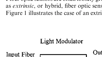
Fiber optic sensors are often loosely grouped into two basic classes referred to asextrinsic, or hybrid, fiber optic sensors andintrinsic, or all-fiber, sensors. Figure 1 illustrates the case of an extrinsic, or hybrid, fiber optic sensor.
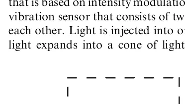
In this case an optical fiber leads up to a ‘‘black box’’ that impresses information onto the light beam in response to an environmental effect. The information could be impressed in terms of intensity, phase, frequency, polarization, spectral content, or other methods. An optical fiber then carries the light with the environmentally impressed information back to an optical and=or electronic processor. In some cases the input optical fiber also acts as the output fiber. The intrinsic or all-fiber sensor shown in Fig. 2 uses an optical fiber to carry the light beam, and the environmental effect impresses information onto the light beam while it is in the fiber. Each of these classes of fibers in turn has many subclasses with, in some cases, sub-subclasses [1] that consist of large numbers of fiber sensors.
In some respects the simplest type of fiber optic sensor is the hybrid type that is based on intensity modulation [7,8]. Figure 3 shows a simple closure or vibration sensor that consists of two optical fibers held in close proximity to each other. Light is injected into one of the optical fibers; when it exits, the light expands into a cone of light whose angle depends on the difference
Figure 2 Intrinsic fiber optic sensors rely on the light beam propagating through the optical fiber being modulated by the environmental effect either directly or through environmentally induced optical path length changes in the fiber itself.
between the index of refraction of the core and cladding of the optical fiber. The amount of light captured by the second optical fiber depends on its acceptance angle and the distance d between the optical fibers. When the distancedis modulated, it in turn results in an intensity modulation of the light captured.
A variation on this type of sensor is shown in Fig. 4. Here a mirror is used that is flexibly mounted to respond to an external effect such as pressure. As the mirror position shifts, the effective separation between the optical fibers shift with a resultant intensity modulation. These types of sensors are useful for such applications as door closures where a reflective strip, in combination with an optical fiber acting to input and catch the output reflected light, can be used.
With two optical fibers arranged in a line, a simple translation sensor can be configured as in Fig. 5. The output from the two detectors can be proportioned to determine the translational position of the input fiber.
Several companies have developed rotary and linear fiber optic position sensors to support applications such as fly-by-light [9]. These sensors attempt
Figure 4 A numerical aperture fiber sensor based on a flexible mirror can be used to measure small vibrations and displacements.
(1) to eliminate electromagnetic interference susceptibility to improve safety and (2) to lower shielding needs to reduce weight. Figure 6 shows a rotary position sensor [10] that consists of a code plate with variable reflectance patches placed so that each position has a unique code. A series of optical fibers is used to determine the presence or absence of a patch.
An example of a linear position sensor using wavelength division mul-tiplexing [11] is illustrated by Fig. 7. Here a broadband light source, which might be a light-emitting diode, is used to couple light into the system. A single optical fiber is used to carry the light beam up to a wavelength division multiplexing (WDM) element that splits the light into separate fibers that are used to interrogate the encoder card and determine linear position. The boxes on the card of Fig. 7 represent highly reflective patches, while the rest of the
Figure 6 Fiber optic rotary position sensor based on reflectance used to measure the rotational position of the shaft via the amount of light reflected from dark and light patches.
card has low reflectance. The reflected signals are then recombined and separated by a second wavelength division multiplexing element so that each interrogating fiber signal is read out by a separate detector.
A second common method of interrogating a position sensor using a single optical fiber is to use time division multiplexing methods [12]. In Fig. 8 a light source is pulsed. The light pulse then propagates down the optical fiber and is split into multiple interrogating fibers. Each of these fibers is arranged so that the fibers have delay lines that separate the return signal from the encoder plate by a time that is longer than the pulse duration. When the returned signals are recombined onto the detector, the net result is an encoded signal burst corresponding to the position of the encoded card.
These sensors have been used to support tests on military and com-mercial aircraft that have demonstrated performance comparable to con-ventional electrical position sensors used for rudder, flap, and throttle position [9]. The principal advantages of the fiber position sensors are immunity to electromagnetic interference and overall weight savings.
Another class of intensity-based fiber optic sensors is based on the principle of total internal reflection. In the case of the sensor inFig. 9,light propagates down the fiber core and hits the angled end of the fiber. If the medium into which the angled end of the fiber is placed has a low enough index of refraction, then virtually all the light is reflected when it hits the mirrored surface and returns via the fiber. If, however, the medium’s index of refraction starts to approach that of the glass, some of the light propagates out of the optical fiber and is lost, resulting in an intensity modulation.
This type of sensor can be used for low-resolution measurement of pressure or index of refraction changes in a liquid or gel with 1% to 10%
accuracy. Variations on this method have also been used to measure liquid level [13], as shown by the probe configuration of Fig. 10. When the liquid level hits the reflecting prism, the light leaks into the liquid, greatly attenu-ating the signal.
Confinement of a propagating light beam to the region of the fiber cores and power transfer from two closely placed fiber cores can be used to produce a series of fiber sensors based on evanescence [14–16].Figure 11illustrates two fiber cores that have been placed in close proximity to one another. For single-mode optical fiber [17], this distance is on the order of 10 to 20 microns.
When single-mode fiber is used, there is considerable leakage of the propagating light beam mode beyond the core region into the cladding or medium around it. If a second fiber core is placed nearby, this evanescent tail
Figure 9 Fiber sensor using critical angle properties of a fiber for pressure=index of refraction measurement via measurements of the light reflected back into the fiber.
will tend to couple to the adjacent fiber core. The amount of cross-coupling depends on a number of parameters, including the wavelength of light, the relative index of refraction of the medium in which the fiber cores are placed, the distance between the cores, and the interaction length. This type of fiber sensor can be used for the measurement of wavelength, spectral filtering, index of refraction, and environmental effects acting on the medium sur-rounding the cores (temperature, pressure, and strain). The difficulty with this sensor that is common to many fiber sensors is optimizing the design so that only the desired parameters are sensed.
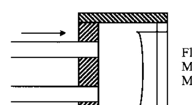
Another way that light may be lost from an optical fiber is when the bend radius of the fiber exceeds the critical angle necessary to confine the light to the core area and there is leakage into the cladding. Local microbending of the fiber can cause this to occur, with resultant intensity modulation of light propagating through an optical fiber. A series of microbend-based fiber sensors has been built to sense vibration, pressure, and other environmental effects [18–20].Figure 12shows a typical layout of this type of device con-sisting of a light source, a section of optical fiber positioned in a microbend transducer designed to intensity-modulate light in response to an environ-mental effect, and a detector. In some cases the microbend transducer can be implemented by using special fiber cabling or optical fiber that is simply optimized to be sensitive to microbending loss.
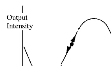
One last example of an intensity-based sensor is the grating-based device [21] shown inFig. 13.Here an input optical light beam is collimated by a lens and passes through a dual grating system. One of the gratings is fixed while the other moves. With acceleration the relative position of the gratings changes, resulting in an intensity-modulated signal on the output optical fiber.
One of the limitations of this type of device is that as the gratings move from a totally transparent to a totally opaque position, the relative sensitivity of the sensor changes, asFig. 14shows. For optimum sensitivity the gratings should be in the half-open=half-closed position. Increasing sensitivity means finer and finer grating spacings, which in turn limit dynamic range.
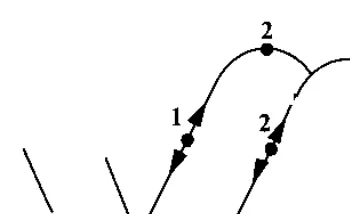
To increase sensitivity without limiting dynamic range, use multiple-part gratings that are offset by 90, as shown inFig. 15.If two outputs are spaced in this manner, the resulting outputs are in quadrature, as shown in
Fig. 16.
Figure 13 Grating-based fiber intensity sensors measure vibration or acceleration via a highly sensitive shutter effect.
When one output is at optimal sensitivity, the other is at its lowest sensitivity, and vice versa. By using both outputs for tracking, one can scan through multiple grating lines, enhancing dynamic range and avoiding the signal fadeout associated with positions of minimal sensitivity.
Intensity-based fiber optic sensors have a series of limitations imposed by variable losses in the system that are not related to the environmental effect to be measured. Potential error sources include variable losses due to con-nectors and splices, microbending loss, macrobending loss, and mechanical creep and misalignment of light sources and detectors. To circumvent these problems, many of the successful higher-performance, intensity-based fiber sensors employ dual wavelengths. One of the wavelengths is used to calibrate out all of the errors due to undesired intensity variations by bypassing the
Figure 14 Dynamic range limitations of the grating-based sensor ofFig. 13are due to smaller grating spacing increasing sensitivity at the expense of range.
Figure 15 Dual grating mask with regions 90out of phase to support quadrature
sensing region. An alternative approach is to use fiber optic sensors that are inherently resistant to errors induced by intensity variations. The next section discusses a series of spectrally based fiber sensors that have this characteristic.
1.3 SPECTRALLY BASED FIBER OPTIC SENSORS
Spectrally based fiber optic sensors depend on a light beam modulated in wavelength by an environmental effect. Examples of these types of fiber sensors include those based on blackbody radiation, absorption, fluorescence, etalons, and dispersive gratings.
One of the simplest of these sensor types is the backbody sensor of Fig. 17. A blackbody cavity is placed at the end of an optical fiber. When the cavity rises in temperature, it starts to glow and act as a light source.
Detectors in combination with narrow band filters are then used to determine the profile of the blackbody curve and, in turn, the temperature, as
Figure 16 Diagram of a quadrature detection method that allows one area of maximum sensitivity while the other reaches a minimum, and vice versa, allowing uniform sensitivity over a wide dynamic range.
in Fig. 18. This type of sensor has been successfully commercialized and used to measure temperature to within a few degrees C under intense RF fields. The performance and accuracy of this sensor are better at higher temperatures and fall off at temperatures on the order of 200C because of low signal-to-noise ratios. Care must be taken to ensure that the hottest spot is the blackbody cavity and not on the optical fiber lead itself, as this can corrupt the integrity of the signal.
Another type of spectrally based temperature sensor, shown in Fig. 19, is based on absorption [22]. In this case a gallium arsenide (GaAs) sensor probe is used in combination with a broadband light source and input=output
Figure 18 Blackbody radiation curves provide unique signatures for each tem-perature.
optical fibers. The absorption profile of the probe is temperature-dependent and may be used to determine temperature.
Fluorescent-based fiber sensors [23–24] are widely used for medical applications and chemical sensing and can also be used for physical parameter measurements such as temperature, viscosity, and humidity. There are a number of configurations for these sensors, Fig. 20 illustrates two of the most common. In the case of the end-tip sensor, light propagates down the fiber to a probe of fluorescent material. The resultant fluorescent signal is captured by the same fiber and directed back to an output demodulator. The light sources can be pulsed, and probes have been made that depend on the time rate of decay of the light pulse.
In the continuous mode, parameters such as viscosity, water vapor content, and degree of cure in carbon fiber reinforced epoxy and thermo-plastic composite materials can be monitored.
An alternative is to use the evanescent properties of the fiber and etch regions of the cladding away and refill them with fluorescent material. By sending a light pulse down the fiber and looking at the resulting fluorescence, a series of sensing regions may be time division multiplexed.
It is also possible to introduce fluorescent dopants into the optical fiber itself. This approach causes the entire optically activated fiber to fluoresce. By using time division multiplexing, various regions of the fiber can be used to make a distributed measurement along the fiber length.
In many cases users of fiber sensors would like to have the fiber optic analog of conventional electronic sensors. An example is the electrical strain
gauge widely used by structural engineers. Fiber grating sensors [25–28] can be configured to have gauge lengths from 1 mm to approximately 1 cm, with sensitivity comparable to conventional strain gauges.
This sensor is fabricated by ‘‘writing’’ a fiber grating into the core of a germanium-doped optical fiber. This can be done in a number of ways. One method, illustrated by Fig. 21, uses two short-wavelength laser beams that are angled to form an interference pattern through the side of the optical fiber. The interference pattern consists of bright and dark bands that represent local changes in the index of refraction in the core region of the fiber. Exposure time for making these gratings varies from minutes to hours, depending on the dopant concentration in the fiber, the wavelengths used, the optical power level, and the imaging optics.
Other methods that have been used include the use of phase masks as well as interference patterns induced by short, high-energy laser pulses. The short duration pulses have the potential to be used to write fiber gratings into the fiber as it is being drawn.
Substantial efforts are being made by laboratories around the world to improve the manufacturability of fiber gratings because they have the potential to be used to support optical communication as well as sensing technology.
Once the fiber grating has been fabricated, the next major issue is how to extract information. When used as a strain sensor, the fiber grating is typically attached to, or embedded in, a structure. As the fiber grating is expanded or
compressed, the grating period expands or contracts, changing the grating’s spectral response.
For a grating operating at 1300 nm, the change in wavelength is about 103nm per microstrain. This type of resolution requires the use of spectral demodulation techniques that are much better than those associated with conventional spectrometers. Several demodulation methods have been sug-gested using fiber gratings, etalons, and interferometers [29,30]. Figure 22 illustrates a system that uses a reference fiber grating. The reference fiber grating acts as a modulator filter. By using similar gratings for the reference and signal gratings and adjusting the reference grating to line up with the active grating, one may implement an accurate closed-loop demodulation system.
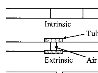
An alternative demodulation system would use fiber etalons such as those shown inFig. 23.One fiber can be mounted on a piezoelectric and the other moved relative to a second fiber end. The spacing of the fiber ends as well as their reflectivity in turn determine the spectral filtering action of the fiber etalon, illustrated byFig. 24.
The fiber etalons in Fig. 23 can also be used as sensors [31–33] for measuring strain, as the distance between mirrors in the fiber determines their transmission characteristics. The mirrors can be fabricated directly into the fiber by cleaving the fiber, coating the end with titanium dioxide, and then resplicing. An alternative approach is to cleave the fiber ends and insert them into a capillary tube with an air gap. Both of these approaches are being investigated for applications where multiple in-line fiber sensors are required. For many applications a single point sensor is adequate. In these situations an etalon can be fabricated independently and attached to the end
of the fiber.Figure 25shows a series of etalons that have been configured to measure pressure, temperature, and refractive index, respectively.
In the case of pressure, the diaphragm has been designed to deflect. Pressure ranges of 15 to 2000 psi can be accommodated by changing the diaphragm thickness with an accuracy of about 0.1% full scale [34]. For temperature the etalon has been formed by silicon–silicon dioxide interfaces. Temperature ranges of 70to 500K can be selected, and for a range of about 100K a resolution of about 0.1K is achievable [34]. For refractive index of liquids, a hole has been formed to allow the flow of the liquid to be measured
Figure 23 Intrinsic fiber etalons are formed by in-line reflective mirrors that can be embedded into the optical fiber. Extrinsic fiber etalons are formed by two mirrored fiber ends in a capillary tube. A fiber etalon-based spectral filter or demodulator is formed by two reflective fiber ends that have a variable spacing.
without the diaphragm deflecting. These devices have been commercialized and are sold with instrument packages [34].
1.4 INTERFEROMETERIC FIBER OPTIC SENSORS
One of the areas of greatest interest has been in the development of high-performance interferometric fiber optic sensors. Substantial efforts have been undertaken on Sagnac interferometers, ring resonators, Mach–Zehnder and Michelson interferometers, as well as dual-mode, polarimetric, grating, and etalon-based interferometers. This section briefly reviews the Sagnac, Mach– Zehnder, and Michelson interferometers.
1.4.1 The Sagnac Interferometer
The Sagnac interferometer has been principally used to measure rotation [35–38] and is a replacement for ring laser gyros and mechanical gyros. It may also be employed to measure time-varying effects such as acoustics, vibration, and slowly varying phenomena such as strain. By using multiple interferometer configurations, it is possible to employ the Sagnac inter-ferometer as a distributed sensor capable of measuring the amplitute and location of a disturbance.
The single most important application of fiber optic sensors in terms of commercial value is the fiber optic gyro. It was recognized very early that the
fiber optic gyro offered the prospect of an all solid-state inertial sensor with no moving parts, unprecedented reliability, and a potential of very low cost.
The potential of the fiber optic gyro is being realized as several manu-facturers worldwide are producing them in large quantities to support auto-mobile navigation systems, pointing and tracking of satellite antennas, inertial measurement systems for commuter aircraft and missiles, and as the backup guidance system for the Boeing 777. They are also being baselined for such future programs as the Comanche helicopter and are being developed to support long-duration space flights.
Other applications using fiber optic gyros include mining operations, tunneling, attitude control for a radio-controlled helicopter, cleaning robots, antenna pointing and tracking, and guidance for unmanned trucks and carriers.
Two types of fiber optic gyros are being developed. The first type is an open-loop fiber optic gyro with a dynamic range on the order of 1000 to 5000 (dynamic range is unitless), with a scale factor accuracy of about 0.5% (this accuracy number includes nonlinearity and hysterisis effects) and sensitivities that vary from less than 0.01=hr to 100=hr and higher [38]. These fiber gyros are generally used for low-cost applications where dynamic range and line-arity are not the crucial issues. The second type is the closed-loop fiber optic gyro that may have a dynamic range of 106and scale factor linearity of 10 ppm or better [38]. These types of fiber optic gyros are primarily targeted at medium- to high-accuracy navigation applications that have high turning rates and require high linearity and large dynamic ranges.
The basic open-loop fiber optic gyro is illustrated by Fig. 26. A broadband light source such as a light-emitting diode is used to couple light into an input=output fiber coupler. The input light beam passes through a polarizer that is used to ensure the reciprocity of the counterpropagating light
beams through the fiber coil. The second central coupler splits the two light beams into the fiber optic coil, where they pass through a modulator used to generate a time-varying output signal indicative of rotation. The modulator is offset from the center of the coil to impress a relative phase difference between the counterpropagating light beams. After passing through the fiber coil, the two light beams recombine the pass back though the polarizer and are directed onto the output detector.
When the fiber gyro is rotated clockwise, the entire coil is displaced, slightly increasing the time it takes light to traverse the fiber optic coil. (Remember that the speed of light is invariant with respect to the frame of reference; thus, coil rotation increases path length when viewed from outside the fiber.) Thus, the clockwise propagating light beam has to go through a slightly longer optical pathlength than the counterclockwise beam, which is moving in a direction opposite to the motion of the fiber coil. The net phase difference between the two beams is proportional to the rotation rate.
By including a phase modulator loop offset from the fiber coil, a time difference in the arrival of the two light beams is introduced, and an optimized demodulation signal can be realized. The right side of Fig. 27 shows this. In the absence of the loops the two light beams traverse the same optical path and are in phase with each other, shown on the left-hand curve of Fig. 27.
The result is that the first or a higher-order odd harmonic can be used as a rotation rate output, resulting in improved dynamic range and linearity.
Further improvements in dynamic range and linearity can be realized by using a ‘‘closed-loop’’ configuration where the phase shift induced by rotation is compensated by an equal and opposite artificially imposed phase shift. One way to accomplish this is to introduce a frequency shifter into the loop, shown in Fig. 29.
The relative frequency difference of the light beams propagating in the fiber loop can be controlled, resulting in a net phase difference proportional to the length of the fiber coil and the frequency shift. In Fig. 29, this is done by using a modulator in the fiber optic coil to generate a phase shift at a rateo.
Figure 29 Closed-loop fiber optic gyros use an artificially induced nonreciprocal phase between counterpropagating light beams to counterbalance rotationally in-duced phase shifts. These fiber gyros have the wide dynamic range and high linearity needed to support stringent navigation requirements.
When the coil is rotated, a first harmonic signal atwis induced with phase that depends on rotation rate in a manner similar to that described above with respect to open-loop fiber gyros. By using the rotationally induced first har-monic as an error signal, one can adjust the frequency shift by using a syn-chronous demodulator behind the detector to integrate the first harmonic signal into a corresponding voltage. This voltage is applied to a voltage-controlled oscillator whose output frequency is applied to the frequency shifter in the loop so that the phase relationship between the counter-propagating light beams is locked to a single value.
It is possible to use the Sagnac interferometer for other sensing and measurement tasks. Examples include slowly varying measurements of strain with 100-micron resolution over distances of about 1 km [39], spectroscopic measurements of wavelength of about 2 nm [40], and optical fiber char-acterization such as thermal expansion to accuracies of about 10 ppm [40]. In each of these applications frequency shifters are used in the Sagnac loop to obtain controllable frequency offsets between the counterpropagating light beams.
Another class of fiber optic sensors, based on the Sagnac interferometer, can be used to measure rapidly varying environmental signals such as sound [41,42]. Figure 30 illustrates two interconnected Sagnac loops [42] that can be used as a distributed acoustic sensor. The WDM (wavelength division mul-tiplexer) in the figure is a device that either couples two wavelengthsl1andl2 in this case) together or separates them.
The sensitivity of this Sagnac acoustic sensor depends on the signal’s location. If the signal is in the center of the loop, the amplification is zero
because both counterpropagating light beams arrive at the center of the loop at the same time. As the signal moves away from the center, the output increases. When two Sagnac loops are superposed, as in Fig. 30,the two outputs may be summed to give an indication of the amplitude of the signal and ratioed to determine position.
Several other combinations of interferometers have been tried for position and amplitude determinations, and the first reported success con-sisted of a combination of the Mach–Zehnder and Sagnac interferometers [41].
1.4.2 The Mach–Zehnder and Michelson Interferometers
One of the great advantages of all fiber interferometers, such as Mach– Zehnder and Michelson interferometers [43] in particular, is that they have extremely flexible geometries and a high sensitivity that allow the possibility of a wide variety of high-performance elements and arrays, as shown in Fig. 31.
Figure 32shows the basic elements of a Mach–Zehnder interferometer,
which are a light source=coupler module, a transducer, and a homodyne demodulator. The light source module usually consists of a long coherence length isolated laser diode, a beamsplitter to produce two light beams, and a means of coupling the beams to the two legs of the transducer. The transducer is configured to sense an environmental effect by isolating one light beam from the environmental effect; using the action of the environmental effect on the transducer induces an optical path length difference between the two light
beams. Typically, a homodyne demodulator is used to detect the difference in optical path length (various heterodyne schemes have also been used) [43].
One of the basis issues with the Mach–Zehnder interferometer is that the sensitivity varies as a function of the relative phase of the light beams in the two legs of the interferometer, as shown in Fig. 33. One way to solve the signal fading problem is to introduce a piezoelectric fiber stretcher into one of the legs and adjust the relative path length of the two legs for optimum sensitivity.
Figure 33 In the absence of compensating demodulation methods, the sensitivity of the Mach–Zehnder varies with the relative phase between the two light beams. It falls to low levels when the light beams are completely in or out of phase.
Another approach has the same quadrature solution as the grating-based fiber sensors discussed earlier.
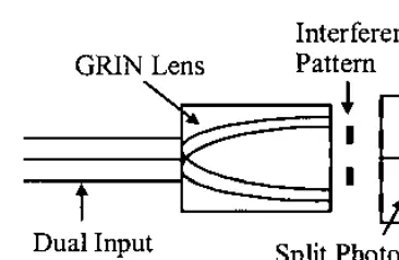
Figure 34 illustrates a homodyne demodulator. The demodulator con-sists of two parallel optical fibers that feed the light beams from the transducer into a graded index (GRIN) lens. The output from the graded index lens is an interference pattern that ‘‘rolls’’ with the relative phase of the two input light beams. If a split detector is used with a photomask arranged so that the opaque and transparent line pairs on the mask in front of the split detector match the interference pattern periodicity and are 90 out of phase on the detector faces, sine and cosine outputs result.
These outputs may be processed using quadrature demodulation elec-tronics, as shown in Fig. 35. The result is a direct measure of the phase difference.
Further improvements on these techniques have been made; notably the phase-generated carrier approach shown inFig. 36.A laser diode is current-modulated, resulting in the output frequency of the laser diode being fre-quency-modulated as well. If a Mach–Zehnder interferometer is arranged so that its reference and signal leg differ in length by an amountðL1L2Þ, then the net phase difference between the two light beams is 2pFðL1L2Þn=c, wherenis in index of refraction of the optical fiber andcis the speed of light in vacuum. If the current modulation is at a rateo, then relative phase differ-ences are modulated at this rate and the output on the detector will be odd and even harmonics of it. The signals riding on the carrier harmonics ofoand 2o
are in quadrature with respect to each other and can be processed using electronics similar to those of Fig. 35.
The Michelson interferometer inFig. 37is in many respects similar to the Mach–Zehnder. The major difference is that mirrors have been put on the ends of the interferometer legs. This results in very high levels of back reflection into the light source, greatly degrading the performance of early systems. Using improved diode pumped YAG (Yttrium Aluminum Garnet)
Figure 36 The phase-generated carrier technique allows quadrature detection via monitoring even and odd harmonics induced by a sinusoidally frequency-modulated light source used in combination with a length offset Mach–Zehnder interferometer to generate a modulated phase output whose first and second harmonics correspond to sine and cosine outputs.
ring lasers as light sources largely overcame these problems. In combination with the recent introduction of phase conjugate mirrors to eliminate polari-zation fading, the Michelson is becoming an alternative for systems that can tolerate the relatively high present cost of these components.
In order to implement an effective Mach–Zehnder or Michelson-based fiber sensor, it is necessary to construct an appropriate transducer. This can involve a fiber coating that could be optimized for acoustic, electric, or magnetic field response. Figure 38 illustrates a two-part coating that consists of a primary and secondary layer. These layers are designed for optimal
Figure 38 Coatings can be used to optimize the sensitivity of fiber sensors. An example would be to use soft and hard coatings over an optical fiber to minimize the acoustic mismatch between acoustic pressure waves in water and the glass optical fiber.
response to pressure waves and for minimal acoustic mismatches between the medium in which the pressure waves propagate and the optical fiber.
These coated fibers are often used in combination with compliant mandrills or strips of material as in Fig. 39 that act to amplify the envir-onmentally induced optical path length difference.
In many cases the mechanical details of the transducer design are critical to good performance such as the seismic=vibration sensor of Fig. 40. Gen-erally, the Mach–Zehnder and Michelson interferometers can be configured with sensitivities that are better than 106radians per square root Hertz. For optical receivers, the noise level decreases as a function of frequency. This phenomenon results in specifications in radians per square root Hertz. As an example, a sensitivity of 106radians per square root Hertz at 1 Hertz means a sensitivity of 106radians, while at 100 Hertz, the sensitivity is 107radians. As an example, a sensitivity of 106radian per square root Hertz means that for a 1-meter-long transducer, less than 1=6 micron of length change can be
Figure 39 Optical fiber bonded to hollow mandrills and strips of environmentally sensitive material are common methods used to mechanically amplify environmental signals for detection by fiber sensors.
resolved at 1-Hertz bandwidths [44]. The best performance for these sensors is usually achieved at higher frequencies because of problems associated with the sensors, also picking up environmental signals due to temperature fluc-tuations, vibrations, and acoustics that limit useful low-frequency sensitivity.
1.5 MULTIPLEXING AND DISTRIBUTED SENSING
Many of the intrinsic and extrinsic sensors may be multiplexed [45], offering the possibility of large numbers of sensors supported by a single fiber optic line. The most commonly employed techniques are time, frequency, wave-length, coherence, polarization, and spatial multiplexing.
Time division multiplexing employs a pulsed light source, launching light into an optical fiber and analyzing the time delay to discriminate between sensors. This technique is commonly employed to support distributed sensors where measurements of strain, temperature, or other parameters are col-lected. Figure 41 illustrates a time division multiplexed system that uses microbend-sensitive areas on pipe joints.
As the pipe joints are stressed, microbending loss increases and the time delay associated with these losses allows the location of faulty joints. The entire length of the fiber can be made microbend-sensitive and Rayleigh scattering loss used to support a distributed sensor that will predominantly measure strain. Other types of scattering from optical pulses propagating down optical fiber have been used to support distributed sensing, notably,
Raman scattering for temperature sensors has been made into a commercial product by York Technology and Hitachi. These units can resolve tempera-ture changes of about 1C with spatial resolution of 1 m for a 1 km sensor using an integration time of about 5 min. Brillioun scattering has been used in laboratory experiments to support both strain and temperature measure-ments.
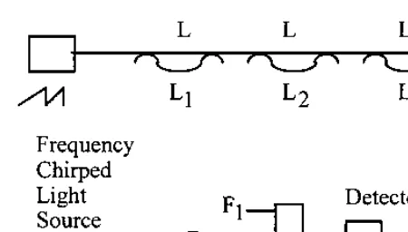
A frequency division multiplexed system is shown in Fig. 42. In this example a laser diode is frequency-chirped by driving it with a sawtooth current drive. Successive Mach–Zehnder interferometers are offset with incremental lengthsðLL1Þ,ðLL2Þ, andðLL3Þ, which differ sufficiently that the resultant carrier frequency of each sensorðdF=dtÞðLLnÞis easily
separable from the other sensors via electronic filtering of the output of the detector.
Wavelength division multiplexing is one of the best methods of multi-plexing as it uses optical power very efficiently. It also has the advantage of being easily integrated into other multiplexing systems, allowing the possi-bility of large numbers of sensors supported in a single fiber line.Figure 43
illustrates a system where a broadband light source, such as a light-emitting diode, is coupled into a series of fiber sensors that reflect signals over wave-length bands that are subsets of the light source spectrum. A dispersive ele-ment, such as grating or prism, is used to separate the signals from the sensors onto separate detectors.
Light sources can have widely varying coherence lengths depending on their spectrum. By using light sources that have coherence lengths that are short compared to offsets between the reference and signal legs in Mach– Zehnder interferometers and between successive sensors, a coherence
plexed system similar to Fig. 44 may be set up. The signal is extracted by putting a rebalancing interferometer in front of each detector so that the sensor signals may be processed. Coherence multiplexing is not used as commonly as time, frequency, and wavelength division multiplexing because of optical power budgets and the additional complexities in setting up the optics properly. It is still a potentially powerful technique and may become more widely used as optical component performance and availability con-tinue to improve, especially in the area of integrated optic chips where control of optical path length differences is relatively straightforward.
One of the least commonly used techniques is polarization multi-plexing. In this case the idea is to launch light with particular polarization
Figure 43 Wavelength division multiplexing is often very energy-efficient. A series of fiber sensors is multiplexed by being arranged to reflect in a particular spectral band that is split via a dispersive element onto separate detectors.
states and extract each state. A possible application is shown in Fig. 45, where light is launched with two orthogonal polarization modes; preserving fiber and evanescent sensors have been set up along each of the axes. A polarizing beamsplitter is used to separate the two signals. There is recent interest in using polarization-preserving fiber in combination with time domain techniques to form polarization-based distributed fiber sen-sors. This has the potential to offer multiple sensing parameters along a single fiber line.
Finally, it is possible to use spatial techniques to generate large sensor arrays using relatively few input and output optical fibers.Figure 46shows a 2 by 2 array of sensors where two light sources are amplitude-modulated at different frequencies. Two sensors are driven at one frequency and two more at the second. The signals from the sensors are put onto two output fibers, each carrying a sensor signal from two sensors at different frequencies.
This sort of multiplexing is easily extended to m input fibers and n output fibers to formmbynarrays of sensors, as inFig. 47.
All of these multiplexing techniques can be used in combination with one another to form extremely large arrays.
1.6 APPLICATIONS
Fiber optic sensors are being developed and used in two major ways. The first is as a direct replacement for existing sensors where the fiber sensor offers
significantly improved performance, reliability, safety, and=or cost ad-vantages to the end user. The second area is the development and deployment of fiber optic sensors in new market areas.
For the case of direct replacement, the inherent value of the fiber sensor, to the customer, has to be sufficiently high to displace older technology. Because this often involves replacing technology the customer is familiar with, the improvements must be substantial.
Figure 47 Extensions of spatial multiplexing theJKsensors can be accomplished by operatingJlight sources atJdifferent frequencies and cross coupling toKoutput fibers.
The most obvious example of a fiber optic sensor succeeding in this arena is the fiber optic gyro, which is displacing both mechanical and ring laser gyros for medium-accuracy devices. As this technology matures, it can be expected that the fiber gyro will dominate large segments of this market.
Significant development efforts are underway in the United States in the area of fly-by-light [9], where conventional electronic sensor technologies are targeted to be replaced by equivalent fiber optic sensor technology that offers sensors with relative immunity to electromagnetic interference, significant weight savings, and safety improvements.
In manufacturing, fiber sensors are being developed to support process control. Often the selling points for these sensors are improvements in environmental ruggedness and safety, especially in areas where electrical discharges could be hazardous.
One other area where fiber optic sensors are being mass-produced is the field of medicine [46–49], where they are being used to measure blood-gas parameters and dosage levels. Because these sensors are completely passive, they pose no electrical-shock threat to the patient and their inherent safety has led to a relatively rapid introduction.
The automotive industry, construction industry, and other traditional sensor users remain relatively untouched by fiber sensors, mainly because of cost considerations. This can be expected to change as the improvements in optoelectronics and fiber optic communications continue to expand along with the continuing emergence of new fiber optic sensors.
New market areas present opportunities where equivalent sensors do not exist. New sensors, once developed, will most likely have a large impact in these areas. A prime example of this is in the area of fiber optic smart struc-tures [50–53]. Fiber optic sensors are being embedded into or attached to materials (1) during the manufacturing process to enhance process control systems, (2) to augment nondestructive evaluation once parts have been made, (3) to form health and damage assessment systems once parts have been assembled into structures, and (4) to enhance control systems. A basic fiber optic smart structure system is shown inFig. 48.
Fiber optic sensors can be embedded in a panel and multiplexed to minimize the number of leads. The signals from the panel are fed back to an optical=electronic processor for decoding. The information is formatted and transmitted to a control system that could be augmenting performance or assessing health. The control system would then act, via a fiber optic link, to modify the structure in response to the environmental effect.
Figure 49shows how the system might be used in manufacturing. Here
These measurements could be used to control the autoclaving process, improving the yield and quality of the parts.
Interesting areas for health and damage assessment systems are on large structures such as buildings, bridges, dams, aircraft, and spacecraft. In order to support these types of structures, it will be necessary to have very large numbers of sensors that are rapidly reconfigurable and redundant. It will also
Figure 49 Smart manufacturing systems offer the prospect of monitoring key parameters of parts as they are being made, which increases yield and lowers overall costs.
be absolutely necessary to demonstrate the value and cost-effectiveness of these systems to the end users.
One approach to this problem is to use fiber sensors that have the potential to be manufactured cheaply in very large quantities while offering superior performance characteristics. Two candidates under investigation are the fiber gratings and etalons described earlier. Both offer the advantages of spectrally based sensors and have the prospect of rapid in-line manufacture. In the case of the fiber grating, the early demonstration of fiber being written into it as it is being pulled has been especially impressive. These fiber sensors could be folded into the wavelength and time division multiplexed modular architecture shown inFig. 50.Here sensors are multiplexed along fiber strings and an optical switch is used to support the many strings. Potentially the fiber strings could have tens or hundreds of sensors, and the optical switches could support a like number of strings. To avoid overloading the system, the output from the sensors could be slowly scanned to determine status in a con-tinuously updated manner.
When an event occur that required a more detailed assessment, the appropriate strings and the sensors in them could be monitored in a high-performance mode. The information from these sensors would then be for-matted and transmitted via a fiber optic link to a subsystem signal processor before introduction onto a health management bus. In the case of avionics the system architecture might look likeFig. 51.The information from the health management bus could be processed and distributed to the pilot or, more
likely, could reduce his or her direct workload, leaving more time for the necessary control functions.
As fiber to the curb and fiber to the home moves closer to reality, there is the prospect of merging fiber optic sensor and communication systems into very large systems capable of monitoring the status of buildings, bridges, highways, and factories over widely dispersed areas. Functions such as fire, police, maintenance scheduling, and emergency response to earthquakes, hurricanes, and tornadoes could be readily integrated into very wide area networks of sensors, as in Fig. 52.
Figure 51 A typical vehicle health management bus for an avionics system would be the interface point for the fiber optic smart structure modules ofFig. 50.
It is also possible to use fiber optic sensors in combination with fiber optic communication links to monitor stress buildup in critical fault locations and dome buildup of volcanoes. These widely dispersed fiber networks may offer the first real means of gathering information necessary to form predic-tion models for these natural hazards.
ACKNOWLEDGMENT
Figures 1 through 52 are drawn from the Fiber Optic Sensor Workbook,
copyright Eric Udd=Blue Road Research, and are used with permission.
REFERENCES
1. E. Udd, ed.,Fiber Optic Sensors: An Introduction for Engineers and Scientists, Wiley, New York, 1991.
2. J. Dakin and B. Culshaw,Optical Fiber Sensors: Principles and Components, Vol. 1, Artech, Boston, 1988.
3. B. Culshaw and J. Dakin,Optical Fiber Sensors: Systems and Applications, Vol. 2, Artech, Norwood, MA, 1989.
4. T. G. Giallorenzi, J. A. Bucaro, A. Dandridge, G. H. Sigel, Jr., J. H. Cole, S. C. Rashleigh, and R. G. Priest, Optical fiber sensor technology,IEEE J. Quant. Elec., QE-18, p. 626, 1982.
5. D. A. Krohn,Fiber Optic Sensors: Fundamentals and Applications, Instrument Society of America, Research Triangle Park, NC, 1988.
6. E. Udd, ed., Fiber optic sensors,Proc. SPIE, CR-44, 1992.
7. S. K. Yao and C. K. Asawa, Fiber optical intensity sensors,IEEE J. Sel. Areas in Communication, SAC-1,3, 1983.
8. N. Lagokos, L. Litovitz, P. Macedo, and R. Mohr, Multimode optical fiber displacement sensor,Appl. Opt.,20, p. 167, 1981.
9. E. Udd, ed., Fly-by-light,Proc. SPIE,2295, 1994.
10. K. Fritsch, Digital angular position sensor using wavelength division multi-plexing,Proc. SPIE,1169, p. 453, 1989.
11. K. Fritsch and G. Beheim, Wavelength division multiplexed digital optical position transducer,Opt. Lett.,11, p. 1, 1986.
12. D. Varshneya and W. L. Glomb, Applications of time and wavelength division multiplexing to digital optical code plates,Proc. SPIE,838, p. 210, 1987. 13. J. W. Snow, A fiber optic fluid level sensor: Practical considerations,Proc. SPIE,
954, p. 88, 1983.
14. T. E. Clark and M. W. Burrell, Thermally switched coupler,Proc. SPIE,986, p. 164, 1988.
15. Y. F. Li and J. W. Lit, Temperature effects of a multimode biconical fiber coupler,Appl. Opt.,25, p. 1765, 1986.
17. D. A. Nolan, P. E. Blaszyk, and E. Udd, Optical fibers, inFiber Optic Sensors: An Introduction for Engineers and Scientists, Eric Udd, ed., Wiley, New York, 1991. 18. J. W. Berthold, W. L. Ghering, and D. Varshneya, Design and characterization of a high temperature, fiber optic pressure transducer,IEEE J. Lightwave Tech., LT-5, p. 1, 1987.
19. D. R. Miers, D. Raj, and J. W. Berthold, Design and characterization of fiber-optic accelerometers,Proc. SPIE,838, p. 314, 1987.
20. W. B. Spillman and R. L. Gravel, Moving fiber optic hydrophone,Optics Lett.,5, p. 30, 1980.
21. E. Udd and P. M. Turek, Single mode fiber optic vibration sensor,Proc. SPIE, 566, p. 135, 1985.
22. D. A. Christensen and J. T. Ives, Fiberoptic temperature probe using a semiconductor sensor, Proc. NATO Advanced Studies Institute, Dordrecht, The Netherlands, p. 361, 1987.
23. S. D. Schwab and R. L. Levy, In-service characterization of composite matrices with an embedded fluorescence optrode sensor,Proc. SPIE,1170, p. 230, 1989. 24. K. T. V. Gratten, R. K. Selli, and A. W. Palmer, A miniature fluorescence referenced glass absorption thermometer, Proc. 4th Intl. Conf. Optical Fiber Sensors, Tokyo, p. 315, 1986.
25. W. W. Morey, G. Meltz, and W. H. Glenn, Bragg–grating temperature and strain sensors,Proc. Optical Fiber Sensors, ’89, Springer-Verlag, Berlin, p. 526, 1989. 26. G. A. Ball, G. Meltz, and W. W. Morey, Polarimetric heterodyning Bragg–
grating fiber laser,Optics Lett.,18, p. 1976, 1993.
27. J. R. Dunphy, G. Meltz, F. P. Lamm, and W. W. Morey, Multi-function, distributed optical fiber sensor for composite cure and response monitoring,
Proc. SPIE,1370, p. 116, 1990.
28. W. W. Morey, Distributed fiber grating sensors,Proc. 7th Optical Fiber Sensor Conf., IREE Australia, Sydney, p. 285, 1990.
29. A. D. Kersey, T. A. Berkoff, and W. W. Morey, Fiber-grating based strain sensor with phase sensitive detection,Proc. SPIE,1777, p. 61, 1992.
30. D. A. Jackson, A. B. Lobo Ribeiro, L. Reekie, and J. L. Archambault, Simple multiplexing scheme for a fiber optic grating sensor network,Optics Lett.,18, p. 1192, 1993.
31. E. W. Saaski, J. C. Hartl, G. L. Mitchell, R. A. Wolthuis, and M. A. Afromowitz, A family of fiber optic sensor using cavity resonator microshifts,Proc. 4th Intl. Conf. Optical Fiber Sensors, Tokyo, 1986.
32. C. E. Lee and H. F. Taylor, Interferometeric optical fiber sensors using internal mirrors,Electronic Lett.,24, p. 193, 1988.
33. C. E. Lee and H. F. Taylor Interferometeric fiber optic temperature sensor using a low coherence light source,Proc. SPIE,1370, p. 356, 1990.
34. Private communication, Elric Saaski, Research International, Woodinville, WA. 35. H. Lefevre,The Fiber Optic Gyroscope, Artech, Norwood, MA, 1993.
36. W. K. Burns, ed.,Optical Fiber Rotation Sensing, Academic Press, San Diego, 1994. 37. R. B. Smith, ed.,Selected Papers on Fiber Optic Gyroscopes, SPIE Milestone
38. S. Ezekial and E. Udd, ed.,Fiber optic gyros: 15th anniversary conference, Proc. SPIE,1585, 1991.
39. R. J. Michal, E. Udd, and J. P. Theriault, Derivative fiber-optic sensors based on the phase nulling optical gyro,Proc. SPIE,719, 1986.
40. E. Udd, R. J. Michal, J. P. Theriault, R. F. Cahill, High accuracy light source wavelength and optical fiber dispersion measurements using the Sagnac interferometer,Proc. 7th Optical Fiber Sensors Conf., IREE Australia, Sydney, p. 329, 1990.
41. J. P. Dakin, D. A. J. Pearce, A. P. Strong, and C. A. Wade, A novel distributed optical fiber sensing system enabling the location of disturbances in a Sagnac loop interferometer,Proc. SPIE,838, p. 325, 1987.
42. E. Udd, Sagnac distributed sensor concepts,Proc. SPIE,1586, p. 46, 1991. 43. A. Dandridge, Fiber optic sensors based on the Mach-Zehnder and Michelson
interferometers, in Fiber Optic Sensors: An Introduction for Engineers and Scientists, Eric Udd, ed., Wiley, New York, 1991.
44. F. Bucholtz, D. M. Dagenais, and K. P. Koo, High frequency fiber-optic magnetometer with 70 ft per square root Hertz resolution,Electronics Lett.,25, p. 1719, 1989.
45. A. D. Kersey, Distributed and multiplexed fiber optic sensors, inFiber Optic Sensors: An Introduction for Engineers and Scientists, Eric Udd, ed., Wiley, New York, 1991.
46. O. S. Wolfbeis and P. Greguss, eds., Biochemical and medical sensors,Proc. SPIE,2085, 1993.
47. A. Katzir, ed., Optical fibers in medicine VIII,Proc. SPIE,1893, 1993. 48. F. P. Milanovich, ed., Fiber optic sensors in medical diagnostics,Proc. SPIE,
1886, 1993.
49. R. A. Lieberman, ed., Chemical, biochemical, and environmental fiber sensors V,
Proc. SPIE,1993.
50. E. Udd, Fiber optic smart structures, inFiber Optic Sensors: An Introduction for Engineers and Scientists, Wiley, New York, 1991.
51. R. Clauss and E. Udd, eds., Fiber optic smart structures and skins IV,Proc. SPIE,1588, 1991.
52. J. S. Sirkis, ed., Smart sensing, processing and instrumentation, Proc. SPIE, 2191, 1994.
2
Fiber Optic Sensors Based upon the
Fabry–Perot Interferometer
Henry F. Taylor
Texas A & M University, College Station, Texas
2.1 INTRODUCTION
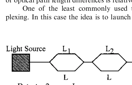
The Fabry–Perot interferometer (FPI), sometimes called the Fabry–Perot etalon, consists of two mirrors of reflectanceR1andR2separated by a cavity of lengthL, as inFig. 1.Since its invention in the late 19th century [1], the bulk-optics version of the FPI has been widely used for high-resolution spectroscopy. In the early 1980s, the first results on fiber optic versions of the FPI were reported. In the late 1980s, fiber Fabry–Perot interferometers began to be applied to the sensing of temperature, strain, and ultrasonic pressure in composite materials. This early work laid the foundation for extensive re-search and development as well as commercialization, which followed during the 1990s.
Fiber Fabry–Perot interferometers are extremely sensitive to pertur-bations that affect the optical path length between the two mirrors. The sensing region can be very compact — equivalent to a ‘‘point’’ transducer in some applications. Unlike other fiber interferometers (Mach–Zehnder, Michelson, Sagnac) used for sensing, the Fabry–Perot contains no fiber couplers — components that can complicate the sensor’s deployment and the interpretation of data. The fiber FPI would appear to be an ideal transducer for many smart structure sensing applications, including those in which the sensor must be embedded in a composite or metal. Finally, these versatile measurement devices are amenable to the application of space division, time division, frequency division, and coherence multiplexing techniques for reducing the cost of multipoint monitoring.