AutoCAD 2005 and AutoCAD LT 2005: No
Experience Required
by David Frey
ISBN:0782143415Sybex © 2004 (667 pages)
Written for the drafting novice, this
introductory book gives you a solid grounding
in the essentials of AutoCAD 2005 and
AutoCAD LT 2005. Step-by-step instructions
and hands-on projects cover each phase of
designing a summer cabin.
Table of Contents
AutoCAD 2005 and AutoCAD LT 2005—No Experience
Required
Introduction
Chapter 1
- Getting to Know AutoCAD
Chapter 2
- Basic Commands to Get Started
Chapter 3
- Setting Up a Drawing
Chapter 4
- Gaining Drawing Strategies: Part 1
Chapter 5
- Gaining Drawing Strategies: Part 2
Chapter 6
- Using Layers to Organize Your Drawing
Chapter 7
- Grouping Objects into Blocks
Chapter 8
- Generating Elevations
Chapter 9
- Working with Hatches and Fills
Chapter 10
- Controlling Text in a Drawing
Chapter 11
- Dimensioning a Drawing
Chapter 14
- Printing an AutoCAD Drawing
Appendix
- A Look at Drawing in 3D
Glossary
Index
Back Cover
AutoCAD 2005 and AutoCAD LT 2005: No Experience
Required
is your step-by-step introduction to the latest
versions of AutoCAD and AutoCAD LT, the world’s
leading customizable CAD software. Inside this
perfectly-paced guide are the clear-cut explanations
and practical tutorials that you need to complete even
the most elaborate AutoCAD projects.
Discover AutoCAD 2005’s newest features as you plan
and develop a complete project. Follow the tutorials
sequentially or begin at any chapter. Either way, you’ll
develop a solid grounding in the essentials and learn
how to use AutoCAD’s productivity tools to get your
work done efficiently.
Gain Critical AutoCAD Skills
Find your way around AutoCAD and LT
Understand the basic commands and how to set
up a drawing
Apply AutoCAD’s coordinate systems
Master drawing strategies
Employ Polar and Object Snap Tracking
Set up and manage layers, colors, and linetypes
Use blocks and Wblocks
another
Generate elevations and orthographic views
Work with hatches and fills
Control text in a drawing
Manage external references
Set up layouts and print an AutoCAD drawing
Use AutoCAD’s enhanced tool palettes
Create and render a 3D model
About the Author
David Frey has been teaching AutoCAD to AEC design
professionals, engineers, and high school students and
teachers for more than a decade. His books for Sybex
include four previous best-selling editions of
AutoCAD:
No Experience Required
and
AutoCAD 2000 Visual
AutoCAD 2005 andAutoCAD LT 2005—No
Experience Required
David Frey SYBEX
Cover Designer: Design Site
Cover Illustrator: Jack D. Myers
Copyright © 2004 SYBEX Inc., 1151 Marina Village Parkway, Alameda, CA 94501. World rights reserved. No part of this publication may be stored in a retrieval system, transmitted, or reproduced in any way, including but not limited to photocopy, photograph, magnetic, or other record, without the prior agreement and written permission of the publisher.
An earlier version of this book was published under the title AutoCAD 2004 and AutoCAD LT 2004: No Experience Required © 2003 SYBEX Inc.
Library of Congress Card Number: 2004104123 ISBN: 0-7821-4341-5 SYBEX and the SYBEX logo are either registered trademarks or
trademarks of SYBEX Inc. in the United States and/or other countries. No Experience Required is a trademark of SYBEX Inc.
Screen reproductions produced with FullShot 99. FullShot 99 © 1991-1999 Inbit Incorporated. All rights reserved. FullShot is a trademark of Inbit Incorporated.
TRADEMARKS: SYBEX has attempted throughout this book to
distinguish proprietary trademarks from descriptive terms by following the capitalization style used by the manufacturer.
The author and publisher have made their best efforts to prepare this book, and the content is based upon final release software whenever possible. Portions of the manuscript may be based upon pre-release versions supplied by software manufacturer(s). The author and the
publisher make no representation or warranties of any kind with regard to the completeness or accuracy of the contents herein and accept no
merchantability, fitness for any particular purpose, or any losses or
damages of any kind caused or alleged to be caused directly or indirectly from this book.
Manufactured in the United States of America 10 9 8 7 6 5 4 3 2 1
To Irv and Ruth, Shirley and Sol, Phyllis and Jonas, and to Dick and Sylvia, for their enthusiasm and support for my writing this book.
Acknowledgments
Many people deserve acknowledgment and gratitude for their contribution to the development and publication of this book. Many thanks to the folks at Sybex who were involved in this project. Monica Baum of the contracts and licensing team helped me finalize the contract. Thanks also to Willem Knibbe, acquisitions editor, for his efforts to gain support for the publication of this book and for his help in getting me started. Mariann Barsolo served well as developmental editor through most of the project and gave excellent answers to my numerous
questions.
I appreciate the efforts of Pat Coleman, who, returning in her role as copyeditor, continued to be diligent at improving the readability of the book. Mae Lum served (for the third time!) as production editor and has again done wonders to coordinate everything, keep me well informed, and make sure the book got done on time. Also, thanks to Sam Sol
Matzkin, who served as the technical editor; his generosity in lending his experience as a civil engineer and as an AutoCAD trainer to this project is greatly appreciated.
Overview
This book was born of the need for a simple yet engaging tutorial that would help beginners step into the world of AutoCAD or AutoCAD LT without feeling intimidated. That tutorial has evolved over the years into a full introduction to the way in which architects and civil and structural engineers use AutoCAD to increase their efficiency and ability to produce state-of-the-art computerized production drawings and designs.
Because AutoCAD and AutoCAD LT are so similar, it makes sense to cover the basics of both programs. For most of the book, the word
AutoCAD stands for both AutoCAD and AutoCAD LT.
When you come to a section of a chapter that applies to AutoCAD only, an icon (shown here) is displayed in the margin to alert you. Then, at the end of that section, extra information for AutoCAD LT users is provided to give you a workaround or otherwise keep you in step with the tutorial. The appendix, which is an introduction to drawing in 3D, applies only to AutoCAD, because AutoCAD LT does not have the 3D commands and features. LT users, be assured: other than the 3D features, LT is much the same program as AutoCAD, with minor differences. You’ll be
prompted when those differences come along.
This book is directed toward AutoCAD and AutoCAD LT novices—users who know how to use a computer and do basic file-managing tasks, such as creating new folders and saving and moving files, but who know
nothing or little about AutoCAD or LT, as we’ll be calling AutoCAD LT throughout the book. If you are new to the construction and design
professions, this book will be an excellent companion as you’re learning AutoCAD. If you’re already practicing in those fields, you’ll immediately be able to apply the skills you’ll pick up from this book to real-world projects. The exercises have been successfully used to train architects, engineers, and contractors, as well as college and high-school students, in the basics of AutoCAD.
through the book—drawing a small cabin—has been kept simple so that it does not require any special training in architecture or construction. Also, most chapters have additional information and exercises
specifically designed for non-AEC users. So anyone wanting to learn AutoCAD will find this book helpful.
What Will You Learn from This Book?
Learning AutoCAD, like learning any complex computer program, requires a significant commitment of time and attention and, to some extent, a tolerance for repetition. You must understand new concepts to operate the program and to appreciate its potential as a drafting and design tool. But to become proficient at AutoCAD, you must also use the commands enough times to gain an intuitive sense of how they work and how parts of a drawing are constructed.
At the end of most chapters, you will find one or more additional
exercises and a checklist of the tools you have learned (or should have learned!). The steps in the tutorial have a degree of repetition built into them that allows you to work through new commands several times and build up confidence before you move on to the next chapter.
Progressing through the book, the chapters fall into four general areas of study:
Chapters 1 through 3 familiarize you with the organization of the screen, go over a few of the most basic commands, and equip you with the tools necessary to set up a new drawing.
Chapters 4 and 5 develop drawing strategies that will help you use commands efficiently.
Chapters 6 through 11 work with AutoCAD’s major features.
Chapters 12 through 14 and the Appendix examine intermediate and advanced AutoCAD features.
In the process of exploring these elements, you will follow the steps involved in laying out the floor plan of a small, three-room cabin. You will then learn how to generate elevations from the floor plan and, eventually, how to set up a title block and print your drawing. Along the way, you will also learn how to do the following:
Set up layers
Put color into your drawing Define and insert blocks Generate elevation views
Place hatch patterns and fills on building components Use text in your drawing
Dimension the floor plan
Chapters in the last part of the book touch on more advanced features of AutoCAD, including:
Drawing a site plan
Using external references
Setting up a drawing for printing with layouts Making a print of your drawing
Working in three dimensions, for AutoCAD users
All these features are taught using the cabin as a continuing project. As a result, you will build up a set of drawings that document your progress through the project and that you can use later as reference material if you find that you need to refresh yourself with material in a specific skill.
At the end of the book is a glossary of terms that are used in the book and are related to AutoCAD and building design, followed by an index.
Files on the Website
find this book’s web page, and then click the Downloads button.
Also on Sybex’s website, in addition to the .dwg files that accompany the book, you can download a bonus chapter, “Making the Internet Work with AutoCAD” and a bonus appendix, “An Introduction to Attributes.” These introduce you to tools for working online with AutoCAD and demonstrate a method for defining attributes and constructing a title block using
Hints for Success
Because this book is essentially a step-by-step tutorial, it has a side effect in common with any tutorial of this type. After you finish a chapter and see that you have progressed further through the cabin project, you may have no idea how you got there and are sure you couldn’t do it again without the help of the step-by-step instructions.
This feeling is a natural result of this kind of learning tool, and you can do a couple of things to get past it. You can do the chapter over again. This may seem tedious, but it has a great advantage. You gain speed in drawing. You’ll accomplish the same task in half the time it took you the first time. If you repeat a chapter a third time, you’ll halve your time again. Each time you repeat a chapter, you can skip more and more of the
explicit instructions, and eventually you’ll be able to execute the commands and finish the chapter by just looking at the figures and glancing at the text. In many ways this is just like learning a musical instrument. You must go slow at first, but over time and through practice, your pace picks up.
Ready, Set…
Chapter 1: Getting to KnowAutoCAD
Opening a new drawing
Getting familiar with the AutoCAD and AutoCAD LT Graphics windows
Modifying the display
Displaying and arranging toolbars
Your introduction to AutoCAD and AutoCAD LT begins with a tour of the features of the screens used by the two programs. In this chapter, you will also learn how to use some tools that help you control the screen’s appearance and how to find and start commands. For the material covered in this chapter, the two applications are almost identical in
Starting Up AutoCAD
If you installed AutoCAD or LT using the default settings for the location of the program files, start AutoCAD by choosing Start Ø All Programs Ø Autodesk Ø AutoCAD 2005 Ø AutoCAD 2005. For LT, choose Start Ø All Programs Ø Autodesk Ø AutoCAD LT 2005 Ø AutoCAD LT 2005. If you customized your installation, find and click the AutoCAD 2005 or the AutoCAD LT 2005 icon to start the program.
The Startup Dialog Box
Dialog boxes with various combinations of buttons and text boxes are used extensively in AutoCAD and LT. You will learn their many functions as you progress through the book.
If AutoCAD or LT opens with the Startup dialog box sitting in front of the AutoCAD Graphics window, your screen will look like Figure 1.1. If the Startup dialog box doesn’t open, read on a little—you’ll see how to display it and then how to suppress it.
Figure 1.1: The Startup dialog box
to revise or update. The second two buttons use templates and wizards to initiate advanced setup routines. The contents of the middle portion of the dialog box depend on which of the four buttons you choose. By
beginning a new drawing, you can get past this dialog box to the AutoCAD Graphics window.
1. Click the Start From Scratch button, the second button from the left.
2. In the Default Settings section, click the Imperial (Feet And Inches) radio button.
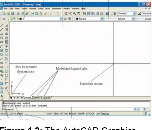
3. Click OK to close the Startup dialog box. Your monitor displays the AutoCAD or LT Graphics window, sometimes called the Graphical User Interface, or GUI (see Figure 1.2).
Figure 1.2: The AutoCAD Graphics window
Radio buttons are round and come in a list or a
group.You can activate only one radio button at a time.
You can always access it on the Help menu.
The toolbars on your screen may not be in exactly the same places as they are shown in Figure 1.2. I recommend that you set your screen to look like the one here, as it will make following through the book that much easier. Later in this chapter, you will see how to move the toolbars, display new ones and place them, and delete them.
Another feature called palettes might be visible on the far-right side of your screen when you start AutoCAD. Palettes can display as a
rectangular area or as a vertical title bar. If they appear, choose Tools Ø Tool Palettes Window to temporarily close the palettes. We’ll take a look at them in Chapters 7 and 9.
Controlling the Way AutoCAD Starts Up
You can set AutoCAD and LT to display or hide the Startup dialog box when you start AutoCAD.
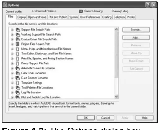
1. From the menu bar, choose Tools Ø Options to open the Options dialog box.
2. Click the System tab to bring it forward.
3. In the General Options section, open the Startup drop-down list.
If you want AutoCAD to display the Startup dialog box, click Show Startup Dialog Box.
If you want AutoCAD to start up with a blank drawing, click Do Not Show A Startup Dialog. 4. Click Apply, and then click OK.
Introduction to the AutoCAD Graphics Window
At the top of the Graphics window sit the title bar, the menu bar, and three toolbars.The title bar is analogous to the title bar in any Windows program. It
contains the program name (AutoCAD or AutoCAD LT) and the title of the current drawing with its path. Below the title bar is the menu bar, where you will see the drop-down menus. Among the drop-down menus, the first two on the left and the last one on the right are Windows menus (meaning that they appear on most Windows applications). These
Windows menus also contain a few commands specific to AutoCAD. The rest of the menus are AutoCAD menus.
Below these menus is the Standard toolbar, which contains 22 command buttons (LT has only 21). Several of these buttons will be familiar to
Windows users; the rest are AutoCAD commands. Just below the
Standard toolbar are the Layers toolbar and the Properties toolbar, which together contain three command buttons and five drop-down lists.
The blank middle section of the screen is called the drawing area. Notice the movable crosshair cursor. The crosshairs on your cursor may not extend completely across the screen. I recommend that you set them to look like they do in the figures in this book, and I will show you how to do this when we make a few changes later in this chapter.
Notice the little box at the intersection of the two crosshair lines. This is one of several forms of the AutoCAD and LT cursor. When you move the cursor off the drawing area, it changes to the standard Windows pointing arrow. As you begin using commands, it will take on other forms,
depending on which step of a command you are in.
book, so you’ll learn how to make it invisible in Chapter 3.
The title bar and menu bar at the top of the LT screen are
identical to those of AutoCAD except that AutoCAD LT appears in the title bar rather than AutoCAD.
At the bottom of the drawing area are three tabs: a Model tab and two Layout tabs. You use these tabs to switch between viewing modes. (I’ll discuss viewing modes in Chapter 13.) Our example shows no toolbars floating in the drawing area, but there are two docked toolbars at the left of the drawing area. Your screen may or may not have the toolbars, or they may be in a different position. If the toolbars are within the drawing area, they will have a colored title bar. For specifics, see the section “The Toolbars” later in this chapter.
Below the drawing area is the Command window.
The Command window is where you tell the program what to do and where the program tells you what’s going on. It’s an important area, and you will need to learn how it works in detail. Three lines of text should be visible. If your screen displays fewer than three lines, you will need to make another line or two visible. You’ll learn how to do this later in this chapter in the section “The Command Window.”
On the left end of the status bar, you’ll see a coordinate readout window. In the middle are eight readout buttons (LT has only seven) that indicate various drawing modes. It is important to learn about the coordinate system and most of these drawing aids (Snap, Grid, Ortho, and Osnap) early as you learn to draw in AutoCAD or LT. They will help you create neat and accurate drawings. Polar and Otrack are advanced drawing tools and will be introduced in Chapter 5. Lwt stands for Lineweight and will be discussed in Chapter 14 in the discussion on plotting. The Model button is an advanced aid that will be covered in Chapter 13. At the far right of the status bar are small icons that indicate the presence of various features for a drawing session. These features are beyond the scope of this book.
LT does not display the Otrack button on the status bar.
This has been a quick introduction to the various parts of the Graphics window. I didn’t mention a couple of items that might be visible on your screen. You might have scroll bars below and to the right of the drawing area, and you might have a menu on the right side of the drawing area. Both features can be useful, but they can also be a hindrance and can take up precious space in the drawing area. They won’t be of any use while working your way through this book, so I suggest that you remove them for now.
To temporarily remove these features, follow these steps:
Figure 1.3: The Options dialog box
2. Click the Display tab, which is shown in Figure 1.4. Focus on the rectangular area titled Window Elements. If scroll bars are visible on the lower and right edges of the drawing area, the Display Scroll Bars In Drawing Window check box will be checked.
Figure 1.4: The Options dialog box open at the Display tab
Don’t click the OK button yet.
Another display setting that you might want to change at this point controls the color of the cursor and the drawing area background. The illustrations in this book show a white background and black crosshair cursor, but you might prefer to reverse the colors. To do so, follow these steps:
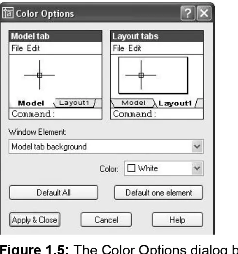
1. In the Window Elements area of the Display tab, click the
Colors button to open the Color Options dialog box (see Figure 1.5). In the middle of the dialog box, in the Window Element drop-down list box, Model Tab Background should be visible. If it’s not, open the drop-down list and select it.
LT doesn’t have the Screen menu, so the option to turn it off is not on LT’s Display tab.
Figure 1.5: The Color Options dialog box
2. Move to the Color drop-down list, which is below the Window Element drop-down list. If your drawing area background is currently white, a square followed by the word White is
background color you want) and select it. The drawing area will now be that color, and the cursor color will change to white, as shown in the Model Tab preview window in the upper-left corner of the dialog box.
3. Click the Apply & Close button to close the Color Options dialog box.
4. Don’t close the Options dialog box yet.
5. If you want the lines of your crosshair cursor to extend
completely across the screen, go to the lower-left corner of the Display tab
(lower-right for LT) and move the slider to change the Crosshair Size setting to 100.
6. Click OK to close the Options dialog box.
Your screen and crosshair cursor will take on their newly assigned colors, and the crosshair lines should extend across the drawing area.
The Command Window
Just below the drawing area is the Command window. This window is actually separate from the drawing area and behaves like a Windows window—that is, you can drag it to a different place on the screen and resize it, although I don’t recommend that you do this at first. If you currently have fewer than three lines of text in the window, you will need to increase the window’s vertical size. To do so, move the cursor to the horizontal boundary between the drawing area and the Command
window until it changes to an up-and-down arrow broken by two parallel horizontal lines.
Hold down the left mouse button and drag the cursor up by approximately the amount that one or two lines of text would take up, and then release the mouse. You should see more lines of text, but you might have to try this a couple of times to display exactly three lines. When you close the program, the new settings will be saved, and the next time you start up AutoCAD, the Command window will display three lines.
The Command window is where you give information to AutoCAD and where AutoCAD prompts you for the next step in executing a command. It is a good practice to get into the habit of keeping an eye on the
Command window as you work on your drawing. Most errors occur when you are not taking a look at it frequently.
Before you begin to draw, take a close look at the menus, toolbars, and keyboard controls.
Drop-Down Menus
The menu bar, just below the title bar (see Figure 1.2 earlier in this
chapter), consists of 11 words and an icon. Click any of these to display a drop-down menu. The icon on the left end and the File and Edit menus are included with all Windows-compatible applications, although they are somewhat customized to work with AutoCAD. The menu associated with the icon contains commands to control the appearance and position of the drawing area.
Commands in the File menu are for opening and saving new and existing drawing files, printing, linking on the Internet, exporting files to another application, choosing basic utility options, and exiting the application. The Edit menu contains the Undo and Redo commands, the Cut and Paste tools, and options for creating links between AutoCAD files and other files. The Help menu (the last menu on the right) works like all Windows Help menus and contains a couple of AutoCAD-specific entries as well, including some online resources and a context-sensitive help feature called the Info Palette.
The other eight menus contain the most-often-used AutoCAD commands. You will find that if you can master the logic of how the commands are organized by menu, you can quickly find the command you want. Here is a short description of each of the other AutoCAD drop-down menus:
View Contains tools for controlling the display of your drawing file.
Insert Contains commands for placing drawings and images or parts of them inside other drawings.
Format Contains commands for setting up the general parameters for a new drawing.
Tools Contains special tools for use while you are working on the current drawing, such as those for finding the length of a line or for running a special macro.
circles) on the screen.
Dimension Contains commands for dimensioning a drawing. Modify Contains commands for changing existing objects in the drawing.
The Toolbars
Just below the drop-down menus is the most extensive of the toolbars— the Standard toolbar.
The 22 icons on the AutoCAD Standard toolbar don’t appear as buttons until you point to them, and they are arranged into seven logical groups. The icons on the left half of the Standard toolbar are mostly for
commands used in all Windows-compatible applications, so you might be familiar with them. The icons on the right half of the Standard toolbar are AutoCAD commands that you use during your regular drawing activities for a variety of tasks. You use these commands to take care of a number of tasks, including the following:
Changing the view of the drawing on the screen
Changing the properties of an object, such as color or linetype Borrowing parts of an unopened drawing to use in your current drawing
Displaying a set of palettes that contain objects you can use in your drawing
LT has only 21 Standard toolbar buttons. It’s missing the Sheet Set Manager button because it doesn’t have this feature.
Toolbar Flyouts
Notice that one icon on the Standard toolbar has a little triangular arrow in the lower-right corner. This arrow indicates that clicking this icon displays more than one command. Follow these steps to see how this special icon works.
2. Rest the arrow on the button for a moment without clicking. A small window opens just below it, displaying the command the button represents. In this case, the window should say “Zoom Window.” This is a tool tip—all buttons have them. Notice the small arrow in the lower-right corner of the icon. This is the multiple-command arrow mentioned earlier.
3. Place the arrow cursor on the button and hold down the left mouse button. A column of eight buttons drops down vertically below the original button. The top button in the column is a duplicate of the button you clicked. This column of buttons is called a toolbar flyout.
4. While still holding down the mouse button, drag the arrow down over each button until you get to the one that has a magnifying glass with a piece of white paper on it. Hold the arrow there until you see the tool tip. It should say “Zoom All.” Now release the mouse button. The flyout disappears, and AutoCAD executes the Zoom All command. Look in the Command window at the bottom of the screen.
The Zoom All command changes the view of your drawing to include special preset parameters. We’ll look at this command in Chapter 3.
5. Look at the Standard toolbar where the Zoom Window button was previously. Notice that it’s been replaced by the Zoom All button.
Tip On a toolbar flyout, the button you select replaces the button that was on the toolbar. This arrangement is handy if you are going to be using the same command several times, because the button for the command is readily available and you don’t have to open the flyout to select it again. The order of the flyout buttons
remains the same, so when you open the Zoom flyout again, the Zoom Window button will be at the top of the list. You will need to become familiar with any flyout buttons you use, because the last one used becomes the representative button on the home toolbar.
The behavior of the Zoom flyout on the Standard toolbar is the same as the behavior of flyouts in general.
Note Whenever you start up AutoCAD or LT for a new drawing session, the toolbars are reset and contain the original flyout buttons.
The toolbar flyouts are actually regular toolbars that have been attached to another toolbar. There are 29 toolbars in all, and only 2 are flyouts— the Zoom flyout I just discussed, and the Insert flyout on the Draw
toolbar. You can display the Zoom and Insert flyouts as regular toolbars, independent of the Standard and Draw toolbars.
toolbars in AutoCAD are almost all for 3D and rendering tools.
Displaying and Arranging Toolbars
In this section, I’ll use the Zoom toolbar to show you some ways you can control and manipulate toolbars. Follow these steps:
1. Right-click any toolbar button on the screen to open the Toolbars menu (see Figure 1.6).
Figure 1.6: The Toolbars menu
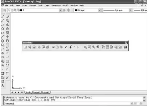
2. Click Zoom to display the Zoom toolbar in the form of a floating box in the drawing area.
Notice that the Zoom toolbar now has a title bar. Toolbars that are positioned on the drawing area have title bars. By placing the cursor on the title bar and holding down the left mouse
button, you can drag the toolbar around the screen. Try this with the Zoom toolbar.
Figure 1.7). As you drag the rectangle to the right of the drawing area and begin to move it off the drawing area onto the right side of the screen, the rectangle becomes taller and thinner.
Figure 1.7: Dragging the Zoom toolbar
4. Release the left mouse button once the toolbar is out of the drawing area. The rectangle changes to the Zoom toolbar,
which is now positioned off the drawing area without its title bar.
Standard and Object Properties toolbars have no title bars— they are docked.
5. Move the cursor arrow to the left end of the Standard toolbar so the point of the arrow is on the two vertical grab bars.
6. Hold down the left mouse button while the cursor arrow is on the Standard toolbar grab bars, and drag the toolbar onto the drawing area. Release the mouse button. The Standard toolbar now has a title bar, and the space it was occupying at the top of the screen has been filled, making the drawing area a little larger, as you can see in Figure 1.8. The Standard toolbar is now a floating toolbar and can be moved around the drawing area.
Figure 1.8: The Standard toolbar on the drawing area
Grab bars are the two lines at the left end of a horizontal toolbar or at the top of a vertical one. They represent the one place to grab a docked toolbar to move it. You can also change a docked toolbar into a floating toolbar by double-clicking its grab bars. To put the Standard toolbar back where it was and delete the Zoom toolbar, follow these steps:
1. Drag the Standard toolbar up to its former position above the Layers and Properties toolbars.
2. Drag the Zoom toolbar back onto the drawing area, using the grab bars. You can easily change the shape of any floating toolbar by dragging its edge. Let’s change the shape of this toolbar.
3. Move the cursor to the far-right edge of the Zoom toolbar until the crosshair cursor changes to a two-way arrow.
Hold down the left mouse button with the cursor on the right edge of the toolbar, and drag the arrow to the left until the rectangle changes shape. Release the mouse button.
You can reshape and reposition each floating toolbar to fit on the drawing area just as you like it. You won’t need the Zoom toolbar just now, so remove it.
4. Move the cursor up to the title bar and click the box with a in it to close the Zoom toolbar.
drawing area as shown earlier in Figure 1.2, continue with the next
section. If these toolbars are in another location on the drawing area, try the steps you used in this section to dock them on the left side. If the toolbars are not visible, right-click any visible toolbar button, and then choose Draw. Drag the Draw toolbar to the left side of the drawing area and dock it. Do the same with the Modify toolbar, positioning it next to the Draw toolbar.
This arrangement of the toolbars will be convenient because you often use commands on these five toolbars. When you need other toolbars temporarily, you can use the Toolbars menu to display them in the drawing area and let them float.
Custom Toolbars
You can customize each toolbar, and you can build your own custom toolbars with only the command buttons you use. You can even design your own buttons for commands that aren’t already represented by buttons on the toolbars. These activities are for more advanced users, however, and are not covered in this book. To find out more about how to customize toolbars, see Mastering AutoCAD 2005 and AutoCAD LT 2005
by George Omura (Sybex, 2004).
Profiles
As you become accustomed to working with AutoCAD, you will develop your own preferences for the layout of the AutoCAD Graphics window, including:
Which toolbars are docked and where The shape of the crosshair cursor
The background color of the drawing area
You control these features from the Options dialog box. If you share your workstation with others, you will find it convenient to set up a profile and save it. That way, if someone changes the organization of your Graphics window, you can quickly restore your preferences. Here’s how to do this:
1. Set the toolbars on your screen as you prefer them.
2. Choose Tools Ø Options to open the Options dialog box, click the Display tab, and make any changes you want to the color of the background and cursor or to the visibility of slide bars.
3. Click the Profiles tab, which is shown in Figure 1.9.
Figure 1.9: The Profiles tab in the Options dialog box
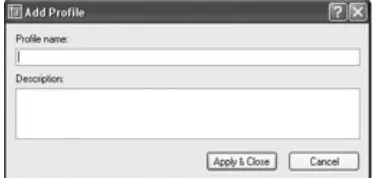
4. Click the Add To List button to open the Add Profile dialog box, which is shown in Figure 1.10.
5. In the Profile Name box, type the name of your profile. You also have the option of entering a description below the name.
6. Click Apply & Close. Your new profile appears in the Available Profiles list. This new profile is the arrangement of the screen that was current when you added your profile to the list.
7. Click OK to close the Options dialog box.
The next time you start up AutoCAD, if the Graphics window is not set up the way you want, follow these steps:
1. Choose Tools Ø Options to open the Options dialog box, and click the Profiles tab.
2. Highlight your profile, and click the Set Current button. 3. Click OK. The Graphics window will then be set to your
The Keyboard
The keyboard is an important tool for entering data and commands. If you are a good typist, you can gain speed in working with AutoCAD by
learning how to enter commands from the keyboard. AutoCAD provides what are called alias keys—single keys or key combinations that will start any of several often-used commands. You can add more or change the existing aliases as you get more familiar with the program.
In addition to the alias keys, you can use several of the F keys (function keys) on the top row of the keyboard as two-way or three-way toggles (switches) to turn AutoCAD functions on and off. Although buttons on the screen duplicate these functions (Snap, Grid, and so on), it is sometimes faster to use the F keys.
Finally, you can activate commands on the drop-down menus from the keyboard, rather than using the mouse. If you press the Alt key, an underlined letter, called a hotkey, appears on each menu. Pressing the key for the underlined letter activates the menu. Each command on the menu also has a hotkey. Once you activate the menu with the hotkey combination, you can type the underlined letter of these commands. For a few commands, this method can be the fastest way to start them up and to select options.
The Mouse
Your mouse will most likely have two or three buttons. (If it’s an IntelliMouse, it will have two or more buttons with a wheel between them.) So far in this chapter, you have used the left mouse button for choosing menus, commands, or command options or for holding down the button and dragging a menu, toolbar, or window. The left mouse button is the one you will be using most often, but you will also use the right mouse button.
While drawing, you will use the right mouse button for the following three operations:
To display a menu containing options relevant to the particular step you are in at the moment
To use in combination with the Shift or Control key to display a menu containing special drawing aids called Object Snaps (see
Chapter 10)
To display a menu of toolbars when the pointer is on any icon of a toolbar that is currently open
If you have a three-button mouse, the middle button is usually
programmed to display the Object Snap menu, instead of using the right button with the Shift key. If you have an IntelliMouse, you can use the wheel in several ways to control the view of your drawing. I’ll cover those methods in subsequent chapters.
AutoCAD makes extensive use of toolbars and the right-click menu
feature. This makes your mouse an important input tool. The keyboard is necessary for inputting numeric data and text, and it has hotkeys and aliases that can speed up your work. But the mouse is the primary tool for starting commands, selecting options, and controlling toolbars.
Are You Experienced?
Now you can…
open a new drawing using the Start Up dialog box
recognize the elements of the AutoCAD Graphics window understand how the Command window works and why it’s important
use drop-down menus
Overview
Understanding coordinate systems Drawing your first figure
Erasing, offsetting, filleting, extending, and trimming lines in a drawing
Now that you have taken a quick tour of the AutoCAD and LT screens, you are ready to begin drawing. In this chapter, you will be introduced to a few basic commands used in drawing with AutoCAD and AutoCAD LT. To get you started, I will guide you through the process of drawing a box (see Figure 2.1).
Figure 2.1: The box to be drawn
The Line Command
In traditional architectural drafting, lines were often drawn to extend slightly past their endpoints (see Figure 2.2). This is no longer done in CAD except for special effects.
Figure 2.2: The box drawn with overlapping lines
The Line command draws a line between locations on existing lines, between geometric figures, or between two points that you can choose anywhere within the drawing area. You can designate these points by clicking them on the screen, by entering the X and Y coordinates for each point in the Command window, or by entering distances and angles at the command line. After you draw the first segment of a line, you can end the command or draw another line segment from the end of the first one. You can continue to draw adjoining line segments for as long as you like. Let’s see how this works.
To be sure that you start with your drawing area set up the way it is set up for this book, choose File Ø Close to close any open drawings. If multiple drawings are open, repeat the Close command for each drawing until you have no drawings open. Your drawing area will be gray and blank with no crosshair cursor, your toolbars will disappear except for five buttons on the Standard toolbar, and you will have only four drop-down menus.
the Create New Drawing dialog box, click the Start From Scratch icon, if it’s not already selected, and click OK. The
menus, crosshair cursor, and toolbars return, and you now have a blank drawing in the drawing area.
2. Glance down at the status bar at the bottom of your screen. All buttons except Model should be off—that is, in an unpushed state. If any of the others appear to be pushed, click them to turn them off.
3. Be sure that the Draw and Modify toolbars are docked on the left side of the drawing area, as shown in Figure 2.3. Refer to
Chapter 1 if you need a reminder on how to display or move toolbars.
Figure 2.3: The Draw and Modify toolbars docked on the left side of the drawing area, and all status bar buttons except Model turned off
4. Click the Line button at the top of the Draw toolbar.
The prompt now tells you that the Line command is started (Command: _line) and that AutoCAD is waiting for you to designate the first point of the line (Specify first point:).
You can also start the Line command by choosing Draw Ø Line or by typing L and pressing the Enter key. 5. Move the cursor onto the drawing area, and using the left
mouse button, click a random point to start a line.
6. Move the cursor away from the point you clicked, and notice how a line segment appears that stretches like a rubber band from the point you just picked to the cursor. The line changes length and direction as you move the cursor.
7. Look at the Command window again, and notice that the prompt has changed.
It is now telling you that AutoCAD is waiting for you to designate the next point (Specify next point or [Undo]:).
8. Continue picking points and adding lines as you move the cursor around the screen (see Figure 2.4). After you draw the third segment, the Command window repeats the Specify next point or [Close/Undo]: prompt each time you pick another point.
9. When you’ve drawn six or seven line segments, press Enter to end the Line command. The cursor separates from the last drawn line segment. Look at the Command window once again.
The Command: prompt has returned to the bottom line. This tells you that no command is running.
In this exercise, you used the left mouse button to select the Line button from the Draw toolbar and also to pick several points in the drawing area to make the line segments. You then pressed Enter ( ) on the keyboard to end the Line command.
Note In the exercises that follow, the Enter symbol ( ) will be used. When I say to “type” or “enter” something, it means to type the data that follows the word type or enter and then to press the Enter key ( ). For example, rather than writing “type L and press the Enter key,” I’ll write “type L .”
Using Coordinates
Try using the Line command again, but instead of picking points in the drawing area with the mouse as you did before, this time enter X and Y coordinates for each point from the keyboard. To see how, follow these steps:
1. Click the Erase button on the Modify toolbar.
You can also start the Erase command by typing e or by choosing Modify Ø Erase.
2. Type all .
3. Press to clear the screen.
Now start drawing lines again by following these steps:
Draw toolbar. 2. Type 2,2 . 3. Type 6,3 . 4. Type 4,6 . 5. Type 1,3 . 6. Type 10,6 . 7. Type 10,1 . 8. Type 2,7 .
9. Press again to end the command.
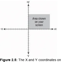
The lines will be similar to those you drew previously, but this time you know where each point is located relative to the 0,0 point. In the drawing area, every point has an absolute X and Y coordinate. In steps 2 through 8, you entered the X and Y coordinates for each point. For a new
Figure 2.5: The X and Y coordinates on the drawing area
Let’s explore how the cursor is related to the coordinates in the drawing. 1. Move the cursor around, and notice the left end of the status
bar at the bottom of the screen. This is the coordinate readout, and it displays the coordinates of the cursor’s position.
2. Move the cursor as close to the lower-left corner of the drawing area as you can without it changing into an arrow. The
coordinate readout should be close to 0.0000,0.0000,0.0000.
Note In AutoCAD, you will see a readout for the Z coordinate as well, but you can ignore it for now because you will be working in only two dimensions for the majority of this book. The Z coordinate will always read 0 until you work in three dimensions (see the Appendix). AutoCAD LT does not have the
readout for the Z coordinate.
readout will change to something close to
0.0000,9.0000,0.0000, indicating that the top of the screen is 9 units from the bottom.
4. Move the cursor one more time to the upper-right corner of the drawing area. The readout will still have a Y coordinate of approximately 9.0000, and the X coordinate will now have a value between 12.0000 and 16.0000, depending on the size of your monitor and how the various parts of the AutoCAD
Graphics window are laid out on your screen. (See Chapter 1
for a recap.)
The drawing area of a new drawing is preset to be 9 units high and 12– 16 units wide, with the lower-left corner of the drawing at the coordinates 0,0.
Note For the moment, it doesn’t matter what measure of distance these units represent. I’ll address that topic in Chapter 3. And don’t worry about the four decimal places in the coordinate readout. The number of places is controlled by a setting you will learn about soon.
Relative Coordinates
Once you understand the coordinate system used by AutoCAD, you can draw lines to any length and in any direction. Look at the box shown earlier in Figure 2.1. Because you know the dimensions, you can
calculate, by adding and subtracting, the absolute coordinates for each
vertex—the connecting point between two line segments—and then use the Line command to draw the shape by entering these coordinates from the keyboard. But AutoCAD offers you several tools for drawing this box much more easily. Two of these tools are the relative Cartesian and the relative polar coordinate systems.
at the coordinate 4,6, and you want the line to extend 8 units to the right, the coordinate that is relative to the first point is 8,0 (8 units in the positive X direction and 0 units in the positive Y direction), while the actual—or
absolute—coordinate of the second point is 12,6.
The relative Cartesian coordinate system uses relative X and Y
coordinates in just the manner shown, and the relative polar coordinate system relies on a distance and an angle relative to the last point
specified. You will probably favor one system over the other, but you need to know both systems because at times, because of the information you have at hand, you will be able to use only one of the two. A limitation of this nature will be illustrated in Chapter 4.
When entering relative coordinates, you need to type an “at” symbol (@) before the coordinates. In the previous example, you would enter the relative Cartesian coordinates as @8,0. The @ lets AutoCAD know that the numbers following it represent coordinates that are relative to the last point designated.
Relative Cartesian Coordinates
Figure 2.6: The relative Cartesian coordinate system
Relative Polar Coordinates
This system requires a known distance and direction from point 1 to point 2. Calculating the distance is straightforward: it’s always positive and is simply the distance away from point 1 that point 2 will be placed. The direction requires a convention for determining an angle. AutoCAD defines right (toward three o’clock) as the direction of the 0° angle. All other directions are determined from a counterclockwise rotation (see
Figure 2.7). On your screen, up is 90°, left is 180°, down is 270°, and a full circle is 360°. To let AutoCAD know that you are entering an angle and not a relative Y coordinate, use the “less than” symbol (<) before the angle and after the distance. So in the previous example, to designate a point 8 units to the right of the first point, you would enter @8<0.
Figure 2.7: The relative polar coordinate system
Drawing the Box
Now that you have the basics, the following exercises will take you through the steps to draw the four lines that form the outline of the box using both relative coordinate systems.
Using Relative Cartesian Coordinates
To begin drawing the box, we’ll use the same drawing.
1. If your drawing is already blank, jump to step 2. If you still have lines on your drawing, start the Erase command, type all , and then press again.
2. Click the Line button at the top of the Draw toolbar.
3. At the Specify First point: prompt in the Command window, type 3,3 . This is an absolute Cartesian coordinate and will be the first point.
4. Type @6,0 . 5. Type @0,5 . 6. Type @-6,0 .
7. Type c . The letter c stands for close. Entering this letter after drawing several lines closes the shape by extending the next line segment from the last point specified to the first point (see
Figure 2.8: The first four lines of the box
Erasing Lines
To prepare to draw the box again, use the Erase command to erase the four lines you have just drawn.
1. Start the Erase command. Notice how the cursor changes from the crosshair to a little square. This is called the pickbox. When you see it on the screen, it’s a sign that AutoCAD is ready for you to select objects on the screen. Also, notice the Command window. It is prompting you to select objects.
2. Place the pickbox on one of the lines and click. The line
changes to a dashed line. This is called ghosting or highlighting. 3. Do the same thing with the rest of the lines.
4. Press . The objects are erased, and the Erase command ends.
Note You have been introduced to two methods of
selecting lines to be erased: typing all and using the pickbox to select them. Throughout the book, you will be introduced to several other ways to select objects. The selection process is important in AutoCAD
Using Relative Polar Coordinates
Now draw the box again using the polar method by following these steps: 1. Start the Line command. (Click the Line button on the Draw
toolbar.) will once again resemble the box shown earlier in Figure 2.8. You can see from this exercise that you can use either method to draw a simple shape. When the shapes you are drawing get more complex and the amount of available information about the shapes varies from
segment to segment, one of the two relative coordinate systems will turn out to be more appropriate. As you start drawing the floor plan of the cabin in Chapters 3 and 4, you will get more practice using these systems.
Some additional tools make the process of drawing simple, orthogonal
lines like these much easier. I’ll introduce these tools in the following three chapters.
The Offset Command
The next task is to create the lines that represent the inside walls of the box. Because they are all equidistant from the lines you have already drawn, the Offset command is the appropriate command to use. You will offset the existing lines 0.5 units to the inside.
Picking the object to offset Indicating the offset direction Here’s how it works:
1. Be sure the prompt line in the Command window reads
Command:. If it doesn’t, press the Esc key until it does. Then click the Offset button on the Modify toolbar. The prompt changes to Specify offset distance or [Through] <1.0000>:. This is a confusing prompt, but it will become clear soon. For now, let’s specify an offset distance through the
keyboard.
You can also start the Offset command by choosing Modify Ø Offset or by typing o .
Warning As important as it is to keep an eye on the
Command window, some of the prompts may not make sense to you until you get used to them.
2. Type .5 for a distance. Now you move to the second stage of the command.
Note that the cursor has changed to a pickbox, and the prompt changes to say Select object to offset or <exit>:.
3. Place the pickbox on one of the lines and click. The selected line ghosts (see Figure 2.9), the cursor changes back to the crosshair, and the prompt changes to Specify point on side to offset:. AutoCAD is telling you that to determine the direction of the offset, you must specify a point on one side of the line or the other. You make the choice by picking
Figure 2.9: The first line to be offset is selected.
4. Pick a point somewhere inside the box. The offset takes place, and the new line is exactly 0.5 units to the inside of the chosen line (see Figure 2.10). Notice that the pickbox comes back on. The Offset command is still running, and you can offset more lines the same distance.
Figure 2.10: The first line is offset. You have three more lines to offset.
5. Click another line; then click inside the box again. The second line is offset.
Figure 2.11: Four lines have been offset.
You can cancel a command at any time by pressing Esc.
Note The offset distance stays set at the last distance you specify—0.5, in this case—until you change it.
7. Press to end the Offset command.
This command is similar to the Line command in that it keeps running until it is stopped. With Offset, after the first offset, the prompts switch between Select object to offset or <exit>: and Specify point on side to offset: until you press to end the command. The inside lines are now drawn, but to complete the box, you need to clean up the intersecting corners. To handle this task efficiently, we will use a new tool called the Fillet command.
Specifying Distances for the Offset Command
The prompt you see in the Command window after starting the Offset command is:
Specify offset distance or [Through] <1.0000>:
Enter a distance from the keyboard.
Pick two points on the screen to establish the offset distance as the distance between those two points.
Press to accept the offset distance that is displayed in the prompt in the angle brackets.
Type t to use the Through option. When you select this option, you are prompted to select the line to offset. You are then prompted to pick a point. The line will be offset to that point. When you pick the next line to offset, you then pick a new point to locate the position of the new line. The Through option allows each line to be offset a different distance.
As you get used to using Offset, you will find uses for each of these options.
The Fillet Command
The Fillet command lets you round off a corner formed by two lines. You control the radius of the curve, so if you set the curve’s radius to zero, the lines will form a sharp corner. In this way, you can clean up corners such as the ones formed by the lines inside the box.
1. At the Command: prompt, click the Fillet button on the Modify toolbar. Notice the Command window:
You can also start the Fillet command by choosing Modify Ø Fillet or by typing f .
2. If your command window displays a radius of 0.0000, go on to step 3. Otherwise, type r , and then type ) to change the radius to zero.
3. Move the cursor—now a pickbox—to the box, and click two intersecting lines, as shown in Figure 2.12. The intersecting lines will both be trimmed to make a sharp corner (see Figure 2.13). The Fillet command automatically ends.
Figure 2.12: Pick two lines to execute the Fillet command.
Figure 2.13: The first cleaned-up corner
4. Press to restart the command, and then fillet two more lines in a similar fashion.
corner until all corners are cleaned up (see Figure 2.14).
Figure 2.14: The box with all corners cleaned up
Once a command has ended, you can restart it by pressing either or the spacebar or by right-clicking and choosing Repeat from the shortcut menu.
Tip In most cases, you will get the same effect by pressing the spacebar as you get by pressing . The exception is when you are entering data in the Command window; in that case, pressing the spacebar just makes a space.
Note If you make a mistake and pick the wrong part of a line or the wrong line, press Esc to end the command and then type u . This will undo the effect of the last command.
Used together like this, the Offset and Fillet commands are a powerful combination of tools to lay out walls on a floor plan drawing. Because these commands are so important, let’s take a closer look at them to see how they work. Both commands are on the Modify toolbar or drop-down menu, both have the option to enter a numeric value or accept the
use and must be restarted for multiple fillets. These two commands are probably the most frequently used tools in AutoCAD. You will learn about more of their uses in later chapters.
The Fillet command has a sister command, the Chamfer command, that is used to bevel corners with straight lines. When the distances for the Chamfer command are set to 0, you can use it to clean up corners in the same way that you use the Fillet command. Some users prefer to use Chamfer rather than Fillet because they don’t bevel corners but may at times use Fillet to round off corners. By using Chamfer to clean up
Completing the Box
The final step in completing the box (see Figure 2.1 earlier in this
chapter) is to make an opening in the bottom wall. From the diagram, you can see that the opening is 2 units wide and set off from the right inside corner by 0.5 units. To make this opening, you will use the Offset
command twice, changing the offset distance for each offset, to create marks for the opening.
Offsetting Lines to Mark an Opening
Follow these steps to establish the precise position of the opening:
1. At the Command: prompt, start the Offset command, either from the Modify toolbar or the Modify menu. Notice the Command window. The default distance is now set at 0.5, the offset
distance you previously set to offset the outside lines of the box to make the inside lines. You want to use this distance again. Press to accept this preset distance.
2. Pick the inside vertical line on the right, and then pick a point to the left of this line. The line is offset to make a new line 0.5 units to its left (see Figure 2.15).
Figure 2.15: Offsetting the first line of the opening
restart the command. This will allow you to reset the offset distance.
4. Enter 2 as the new offset distance and press .
5. Click the new line, and then pick a point to the left. Press to end the Offset command (see Figure 2.16).
Figure 2.16: Offsetting the second line of the opening
You now have two new lines indicating where the opening will be. You can use these lines to form the opening using the Extend and Trim commands.
Tip The ”buttons” you have been clicking in this chapter are also referred to as “icons” and “tools.” When they are in dialog boxes or on the status bar, they have icons (little pictures) on them and actually look like buttons to push. When they are on the toolbars, they look like icons. But when you move the pointer arrow cursor onto one, it takes on the appearance of a button with an icon on it. I will use all three terms—button, icon, and tool—
interchangeably in this book.
Extending Lines
command may be a little tricky at first until you see how it works. Once you understand it, however, it will become automatic. The command has two steps: first, you pick the boundary edge or edges, and second, you pick the lines you want to extend to meet those boundary edges. After selecting the boundary edges, you must press before you begin selecting lines to extend.
1. To begin the Extend command, click the Extend button on the Modify toolbar. Notice the Command window.
The bottom line says Select objects:, but in this case you need to observe the bottom two lines of text in order to know that AutoCAD is prompting you to select boundary edges.
2. Pick the very bottom horizontal line (see Figure 2.17) and press .
Figure 2.17: Selecting a line to be a boundary edge
You can also start the Extend command by choosing Modify Ø Extend from the Modify drop-down menu or by typing ex .
selecting objects.” But it doesn’t. You have to train yourself to press when you finish selecting objects in order to get out of selection mode and move on to the next step in the command.
3. Pick the two new vertical lines created by the Offset command. Be sure to place the pickbox somewhere on the lower halves of these lines, or AutoCAD will ignore your picks. The lines are extended to the boundary edge line. Press to end the Extend command (see Figure 2.18).
Figure 2.18: The lines are extended to the boundary edge.
Trimming Lines
The final step is to trim away the horizontal lines to complete the opening. To do this, you use the Trim command. As with the Extend command, there are two steps. The first is to select reference lines—in this case, they’re called cutting edges because they determine the edge or edges to which a line is trimmed. The second step is to pick the lines that are to be trimmed.
2. Pick the two vertical offset lines that were just extended as your cutting edges, and then press (see Figure 2.19).
You can also start the Trim command by choosing Modify Ø Trim from the Modify drop-down menu or by typing tr .
Figure 2.19: Lines selected to be cutting edges
3. Pick the two horizontal lines across the opening somewhere between the cutting edge lines (see Figure 2.20).
Figure 2.21: Lines are trimmed to make the opening.
Note If you trim the wrong line or wrong part of a line, you can click the Undo button on the Standard toolbar. This will undo the last trim without canceling the Trim command, and you can try again.
Now let’s remove the extra part of our trimming guide lines.
1. Press twice—once to end the Trim command and again to restart it. This will allow you to pick new cutting edges for another trim operation.
2. Pick the two upper horizontal lines next to the opening as your cutting edges, shown in Figure 2.22, and press .
3. Pick the two vertical lines that extend above the new opening. Be sure to pick them above the opening (see Figure 2.23). The lines are trimmed away, and the opening is complete. Press to end the Trim command (see Figure 2.24).
Figure 2.23: Lines picked to be trimmed
Figure 2.24: The completed trim
Congratulations! You have just completed the first drawing project in this book and have covered all the tools in this chapter. These skills will be useful as you learn how to work on drawings for actual projects.
The box you drew was 6 units by 5 units, but how big was it? You really don’t know at this time, because the units could represent any actual distance: inches, feet, meters, miles, and so on. Also, the box was positioned conveniently on the screen so you didn’t have any problem viewing it. What if you were drawing a building that was 200 feet long and 60 feet wide? In the next chapter, you will learn how to set up a drawing for a project of a specific size.
If You Would Like More Practice…
Draw the following object shown in Figure 2.25.Figure 2.25: Practice drawing
You can use the same tools and strategy used to draw the box. Choose File Ø New to start a new drawing, and click the Start From Scratch button in the Create New Drawing dialog box. Here’s a summary of the steps to follow:
Ignore the three openings at first.
Draw the outside edge of the shape using one of the relative coordinate systems. To make sure the box fits on your screen, start the outline of the box in the lower-left corner at the absolute coordinate of 1,0.5.
Offset the outside lines to create the inside wall. Fillet the corners to clean them up.
Use the Offset, Extend, and Trim commands to create the three openings.
Are You Experienced?
Now you can…
understand the basics of coordinates
discern between the two relative coordinate systems used by AutoCAD
Overview
Setting up drawing units Using a grid
Zooming in and out of a drawing Naming and saving a file
In Chapter 2, we explored the default drawing area that is set up when you open a new drawing. It is probably 9 units high by 12 to 16 units wide, depending on the size of your monitor. You drew the box within this area. If you drew the additional diagram offered as a supplemental
exercise, the drawing area was set up the same way.
For most of the rest of this book, you will be developing drawings for a cabin with outside wall dimensions of 25' 16', but the tools you use and the skills you learn will enable you to draw objects of any size. In this chapter, you will learn how to set up the drawing area to lay out the floor plan for a building of a specific size. The decimal units with which you have been drawing until now will be changed to feet and inches, and the drawing area will be transformed so that it can represent an area large enough to display the floor plan of the cabin you will be drawing.
Drawing Units
When you draw lines of a precise length in AutoCAD, you use one of five kinds of linear units. Angular units can also be any of five types. You can select the type of units to use, or you can accept the default Decimal units that you used in the last chapter.
When you start a new drawing, AutoCAD displays a blank drawing called Drawingn.dwg with the linear and angular units set to decimal numbers. The units and other basic setup parameters applied to this new drawing are based on a prototype drawing with default settings—including those for the units. This chapter will cover some of the tools for changing the basic parameters of a new drawing so you can tailor it to the cabin project or for your own project. You will start by setting up new units.
1. With AutoCAD running, close all drawings, and then click the New button (on the Standard toolbar) to start a new drawing. Depending on the way AutoCAD is set up, you will see either the Create New Drawing dialog box or the Select Template dialog box. If you see the Create New Drawing dialog box, be sure the Start From Scratch option is selected and click OK. If you see the Select Template dialog box, click the arrow to the right of the Open button and select Open With No Template -Imperial.
To get started with the steps in this chapter, check to be sure that, for now, all the status bar buttons except Model are clicked to the Off position—that is, they will appear unpushed.
When we get to Chapter 10, you will see how to use templates to set up drawings.