by Mark Middlebrook
FOR
FOR
by Mark Middlebrook
FOR
Hoboken, NJ 07030-5774
Copyright © 2004 by Wiley Publishing, Inc., Indianapolis, Indiana Published by Wiley Publishing, Inc., Indianapolis, Indiana Published simultaneously in Canada
No part of this publication may be reproduced, stored in a retrieval system or transmitted in any form or by any means, electronic, mechanical, photocopying, recording, scanning or otherwise, except as per-mitted under Sections 107 or 108 of the 1976 United States Copyright Act, without either the prior written permission of the Publisher, or authorization through payment of the appropriate per-copy fee to the Copyright Clearance Center, 222 Rosewood Drive, Danvers, MA 01923, (978) 750-8400, fax (978) 646-8600. Requests to the Publisher for permission should be addressed to the Legal Department, Wiley Publishing, Inc., 10475 Crosspoint Blvd., Indianapolis, IN 46256, (317) 572-3447, fax (317) 572-4447, e-mail:
Trademarks:Wiley, the Wiley Publishing logo, For Dummies, the Dummies Man logo, A Reference for the Rest of Us!, The Dummies Way, Dummies Daily, The Fun and Easy Way, Dummies.com, and related trade dress are trademarks or registered trademarks of John Wiley & Sons, Inc. and/or its affiliates in the United States and other countries, and may not be used without written permission. AutoCAD is a registered trademark of Autodesk, Inc. All other trademarks are the property of their respective owners. Wiley Publishing, Inc., is not associated with any product or vendor mentioned in this book.
LIMIT OF LIABILITY/DISCLAIMER OF WARRANTY: THE PUBLISHER AND THE AUTHOR MAKE NO REP-RESENTATIONS OR WARRANTIES WITH RESPECT TO THE ACCURACY OR COMPLETENESS OF THE CONTENTS OF THIS WORK AND SPECIFICALLY DISCLAIM ALL WARRANTIES, INCLUDING WITHOUT LIMITATION WARRANTIES OF FITNESS FOR A PARTICULAR PURPOSE. NO WARRANTY MAY BE CRE-ATED OR EXTENDED BY SALES OR PROMOTIONAL MATERIALS. THE ADVICE AND STRATEGIES CON-TAINED HEREIN MAY NOT BE SUITABLE FOR EVERY SITUATION. THIS WORK IS SOLD WITH THE UNDERSTANDING THAT THE PUBLISHER IS NOT ENGAGED IN RENDERING LEGAL, ACCOUNTING, OR OTHER PROFESSIONAL SERVICES. IF PROFESSIONAL ASSISTANCE IS REQUIRED, THE SERVICES OF A COMPETENT PROFESSIONAL PERSON SHOULD BE SOUGHT. NEITHER THE PUBLISHER NOR THE AUTHOR SHALL BE LIABLE FOR DAMAGES ARISING HEREFROM. THE FACT THAT AN ORGANIZATION OR WEBSITE IS REFERRED TO IN THIS WORK AS A CITATION AND/OR A POTENTIAL SOURCE OF FUR-THER INFORMATION DOES NOT MEAN THAT THE AUTHOR OR THE PUBLISHER ENDORSES THE INFOR-MATION THE ORGANIZATION OR WEBSITE MAY PROVIDE OR RECOMMENDATIONS IT MAY MAKE. FURTHER, READERS SHOULD BE AWARE THAT INTERNET WEBSITES LISTED IN THIS WORK MAY HAVE CHANGED OR DISAPPEARED BETWEEN WHEN THIS WORK WAS WRITTEN AND WHEN IT IS READ.
For general information on our other products and services or to obtain technical support, please contact our Customer Care Department within the U.S. at 800-762-2974, outside the U.S. at 317-572-3993, or fax 317-572-4002.
Wiley also publishes its books in a variety of electronic formats. Some content that appears in print may not be available in electronic books.
Library of Congress Control Number: 2004102367 ISBN: 0-7645-7138-9
Manufactured in the United States of America 10 9 8 7 6 5 4 3 2 1
To Puck and Pretzel, two absolute AutoCAD dummies who never cease to inspire and amuse. It was during walks in the woods with them that I origi-nally worked out some of the details of these chapters. I’m pretty sure that Puck could learn AutoCAD, if only he could figure out how to manipulate a mouse. Pretzel, on the other hand, is too interested in squirrels to bother with mice.
Author’s Acknowledgments
Some of the people who helped bring this book to market include the following:
Acquisitions, Editorial, and Media Development
Project Editor:Christine Berman
Acquisitions Editor:Terri Varveris
Copy Editor:Christine Berman
Technical Editor:David Byrnes
Editorial Manager:Carol Sheehan
Media Development Supervisor:
Richard Graves
Editorial Assistant:Amanda Foxworth
Cartoons:Rich Tennant (www.the5thwave.com)
Production
Project Coordinator: Courtney MacIntyre
Layout and Graphics: Amanda Carter, Andrea Dahl, Lauren Goddard, Denny Hager, Michael Kruzil, Jacque Schneider, Melanee Wolven
Proofreaders: Laura Albert, Andy Hollandbeck, Carl Pierce, Brian H. Walls,
TECHBOOKS Production Services
Indexer: TECHBOOKS Production Services
Publishing and Editorial for Technology Dummies
Richard Swadley,Vice President and Executive Group Publisher
Andy Cummings,Vice President and Publisher
Mary C. Corder,Editorial Director
Publishing for Consumer Dummies
Diane Graves Steele,Vice President and Publisher
Joyce Pepple,Acquisitions Director
Composition Services
Gerry Fahey,Vice President of Production Services
Introduction ...1
Part I: AutoCAD 101 ...7
Chapter 1: Introducing AutoCAD and AutoCAD LT 2005 ...9
Chapter 2: Le Tour de AutoCAD 2005 ...17
Chapter 3: Setup for Success ...41
Part II: Let There Be Lines...71
Chapter 4: Get Ready to Draw ...73
Chapter 5: Where to Draw the Line...101
Chapter 6: Edit for Credit ...129
Chapter 7: A Zoom with a View ...167
Chapter 8: On a 3D Spree...179
Part III: If Drawings Could Talk...203
Chapter 9: Text with Character ...205
Chapter 10: Entering New Dimensions ...229
Chapter 11: Down the Hatch ...255
Chapter 12: The Plot Thickens ...267
Part IV: Share and Share Alike ...293
Chapter 13: Playing Blocks and Rasteroids ...295
Chapter 14: Sheet Sets without Regrets ...321
Chapter 15: CAD Standards Rule ...337
Chapter 16: Drawing on the Internet...347
Part V: The Part of Tens ...367
Chapter 17: Ten Ways to Do No Harm ...369
Chapter 18: Ten Ways to Swap Drawing Data with Other People and Programs ...373
Introduction...1
What’s Not in This Book ...1
Who Are — and Aren’t — You?...2
How This Book Is Organized ...2
Part I: AutoCAD 101 ...3
Part II: Let There Be Lines ...3
Part III: If Drawings Could Talk...4
Part IV: Share and Share Alike...4
Part V: The Part of Tens...4
Icons Used in This Book ...5
A Few Conventions — Just in Case ...5
Part I: AutoCAD 101 ...7
Chapter 1: Introducing AutoCAD and AutoCAD LT 2005 . . . .9
Why AutoCAD?...10
The Importance of Being DWG ...11
Seeing the LT ...13
Staying Alive with 2005 ...14
Chapter 2 : Le Tour de AutoCAD 2005 . . . .17
AutoCAD Does Windows ...18
AutoCAD’s Opening Screen Cuisine ...19
Standard Windows fare ...19
Looking for Mr. Status Bar ...23
Take an order: The command line area ...26
Main course: The drawing area ...30
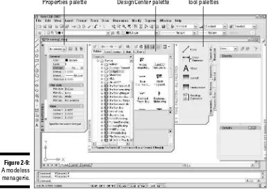
A Palette-Cleanser ...33
What Really Makes AutoCAD Cook? ...35
Sizzling system variables...35
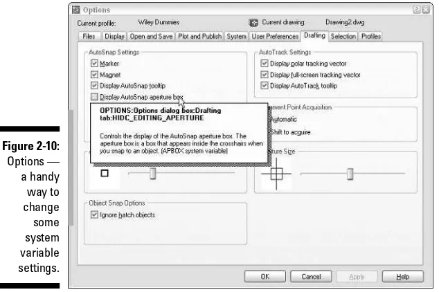
Delicious dialog boxes ...37
Fun with F1 ...38
Chapter 3 : Setup for Success . . . .41
An Appetizing Setup Strategy ...42
Choosing your units ...44
Weighing your scales...45
Thinking about paper...47
Defending your border...50
Getting Creative with Templates ...51
The Main Course: Model Space ...54
Setting your units ...54
Telling your drawing its limits ...55
Making the drawing area snap-py (and grid-dy)...57
Setting linetype and dimension scales...59
Entering drawing properties ...61
Plot Layouts for Any Palate...62
Creating a layout...63
Copying and changing layouts...66
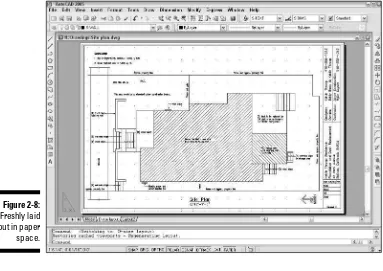
Lost in paper space ...67
Cooking Up Terrific Templates ...68
Part II: Let There Be Lines ...71
Chapter 4: Get Ready to Draw . . . .73
Drawing and Editing with AutoCAD ...73
Managing Your Properties...74
Putting it on a layer ...75
Accumulating properties ...77
Precise-liness Is Next to CAD-liness ...88
Keyboard capers: Coordinate entry...90
Grab an object and make it snappy...92
Other precision practices...97
Chapter 5: Where to Draw the Line . . . .101
Introducing the AutoCAD Drawing Commands ...102
The Straight and Narrow: Lines, Polylines, and Polygons ...104
Toe the line ...104
Connect the lines with polyline ...107
Square off with rectangle...112
Choose your sides with polygon ...113
(Throwing) Curves ...115
Going full circle ...115
Arc-y-ology...116
Ellipses (S. Grant?) ...119
Splines: The sketchy, sinuous curves ...121
Donuts: The circles with a difference ...123
Revision clouds on the horizon ...124
Chapter 6: Edit for Credit . . . .129
Commanding and Selecting...129
Command-first editing ...130
Selection-first editing ...130
Choosing an editing style ...130
Grab It ...131
One-by-one selection...132
Selection boxes left and right ...132
Perfecting Selecting...134
Ready, Get Set, Edit! ...137
The Big Three: Move, CoPy, and Stretch ...138
More manipulations ...147
Copy, or a kinder, gentler Move ...160
A warm-up Stretch ...162
Chapter 7: A Zoom with a View . . . .167
Zoom and Pan with Glass and Hand ...167
Out of the frying pan . . . ...169
Time to zoom ...170
A View by Any Other Name. . ...171
Looking Around in Layout Land ...173
Degenerating and Regenerating ...176
Chapter 8: On a 3D Spree . . . .179
Is 3D for Me?...180
Getting Your 3D Bearings ...184
Model space viewports left and right ...184
Seeing the world from new viewpoints...185
Dynamic viewpoints with 3DOrbit ...187
A Cartesian Orientation...190
Coordinate systems: The WCS and UCS ...190
Specifying coordinates in 3D...191
Drawing in 3D...193
Drawing 3D lines and polylines...193
Extruding from 2D to 3D ...194
Meshing around with surface meshes ...196
A solid(s) foundation ...197
Editing in three dimensions ...199
Part III: If Drawings Could Talk ...203
Chapter 9: Text with Character . . . .205
Getting Ready to Write...206
Simply stylish text ...206
Taking your text to new heights ...209
One line or two?...212
Your text will be justified...212
Using the Same Old Line...213
Saying More in Multiline Text ...215
Making it with mText...215
New mText might in AutoCAD 2005 ...218
Keeping tabs (and indents) on your mText ...220
Modifying mText ...222
Setting the Text Table ...223
Tables have style, too ...223
Creating and editing tables ...224
Checking Out Your Spelling...227
Chapter 10: Entering New Dimensions . . . .229
Discovering New Dimensions ...231
Anatomy of a dimension ...231
A field guide to dimensions...232
Dimension associativity...233
Pulling out your dimension tools ...234
Doing Dimensions with Style(s) ...235
Borrowing existing dimension styles ...235
Creating and managing dimension styles...237
Adjusting style settings...239
Drawing Dimensions ...242
Lining up some linear dimensions...243
Drawing other kinds of dimensions ...246
Trans-spatial dimensioning ...246
Editing Dimensions ...247
Editing dimension geometry ...247
Editing dimension text ...248
Controlling and editing dimension associativity...249
Pointy-Headed Leaders...250
Chapter 11: Down the Hatch . . . .255
Hatch . . . Hatch . . . Hatchoo...256
Pushing the Boundary (of) Hatch ...258
Hatch from scratch...259
Getting it right: Hatch angle and scale...261
Hatching that knows its place...264
Have palette, will hatch ...264
Editing Hatch Objects ...264
Chapter 12: The Plot Thickens . . . .267
You Say Printing, I Say Plotting...267
Get with the system...268
Configure it out ...269
A Simple Plot...270
Plotting success in 16 steps ...271
Preview one, two ...274
Instead of fit, scale it ...275
Plotting the Layout of the Land ...276
About paper space layouts and plotting ...276
The path to paper space layout plotting success ...277
Plotting Lineweights and Colors ...279
Plotting with style...279
Plotting through thick and thin ...283
Plotting in color ...285
It’s a (Page) Setup!...287
Continuing the Plot Dialog ...288
Troubles with Plotting ...291
Part IV: Share and Share Alike...293
Chapter 13: Playing Blocks and Rasteroids . . . .295
Rocking with Blocks...296
Creating block definitions ...298
Inserting blocks ...301
Attributes: Fill-in-the-blank blocks ...304
Exploding blocks ...308
Going External ...309
Becoming attached to your xrefs ...311
Layer-palooza...312
Creating and editing an external reference file...313
Forging an xref path ...313
Managing xrefs ...314
Blocks, Xrefs, and Drawing Organization ...316
Mastering the Raster...316
Attaching an image...318
Managing images ...319
Chapter 14: Sheet Sets without Regrets . . . .321
Taming Sheet Sets ...322
The Sheet Set Setup ...325
Getting Your Sheets Together ...326
Adding existing sheets to a set ...327
Sheet subsets ...328
Creating new sheets for a set ...329
Assembling sheet views from resource drawings ...330
Making an Automatic Sheet List ...333
Chapter 15: CAD Standards Rule . . . .337
Why CAD Standards? ...338
Which CAD Standards? ...339
What Needs to Be Standardized? ...341
Plotting...341
Layers...342
Other stuff ...343
Cool Standards Tools ...344
Chapter 16: Drawing on the Internet . . . .347
The Internet and AutoCAD: An Overview ...348
Sending Strategies ...350
Send it with ETRANSMIT ...351
Rapid eTransmit ...352
Transmitting multiple drawings ...354
FTP for you and me ...355
Bad reception? ...355
Help from the Reference Manager...356
Drawing Web Format — Not Just for the Web ...358
All about DWF ...358
ePlot, not replot ...359
Making DWFs with ePlot ...360
Making DWFs (or Plots) with PUBLISH ...361
Hand-y objects ...363
Autodesk Express Viewer ...363
The Drawing Protection Racket...364
Part V: The Part of Tens ...367
Chapter 17: Ten Ways to Do No Harm . . . .369
Be Precise ...369
Control Properties by Layer ...369
Know Your Drawing Scale Factor ...370
Know Your Space...370
If Someone (Sheet) Set It, Don’t Forget It ...370
Don’t Cram Your Geometry...371
Freeze Instead of Erase...371
Use CAD Standards ...371
Save and Back Up Drawings Regularly ...372
Chapter 18: Ten Ways to Swap Drawing Data
with Other People and Programs . . . .373
DWG ...374
DXF ...376
DWF ...376
PDF ...376
WMF ...377
BMP, JPEG, TIFF, and Other Raster Formats ...377
Windows Clipboard...379
OLE ...379
Screen Capture ...380
TXT and RTF ...381
I
t’s amazing to think that AutoCAD came into being over two decades ago, at a time when most people thought that personal computers weren’t capable of industrial-strength tasks like CAD. (The acronym stands for Computer-Aided Drafting, Computer-Aided Design, or both, depending on whom you talk to). It’s almost as amazing that, 20 years after its birth, AutoCAD remains the king of the microcomputer CAD hill by a tall margin. Many competing CAD programs have come to challenge AutoCAD, many have fallen, and a few are still around. One hears rumblings that the long-term future of CAD may belong to special-purpose, 3D-based software such as the Autodesk Inventor and Revit programs. Whether or not those rumblings amplify into a roar remains to be seen, but for the present and the near future anyway, AutoCAD is where the CAD action is.In its evolution, AutoCAD has grown more complex, in part to keep up with the increasing complexity of the design and drafting processes that AutoCAD is intended to serve. It’s not enough just to draw nice-looking lines anymore. If you want to play CAD with the big boys and girls, you need to organize the objects you draw, their properties, and the files in which they reside in appropriate ways. You need to coordinate your CAD work with other people in your office who will be working on or making use of the same drawings. You need to be savvy about shipping drawings around via the Internet.
AutoCAD 2005 provides the tools for doing all these things, but it’s not always easy to figure out which hammer to pick up or which nail to bang on first. With this book, you have an excellent chance of creating a presentable, usable, printable, and sharable drawing on your first or second try without putting a T square through your computer screen in frustration.
What’s Not in This Book
Unlike many other For Dummiesbooks, this one does tell you to consult the official software documentation sometimes. AutoCAD is just too big and com-plicated for a single book to attempt to describe it completely.
months later than the regular book.) I do occasionally mention differences with previous versions, going back to the highly popular AutoCAD Release 14, so that everyone has some context and upgraders can more readily under-stand the differences. I also mention the important differences between full AutoCAD and AutoCAD LT, so that you’ll know what you — or your LT-using colleagues — are missing. This book does not cover the discipline-specific features in AutoCAD-based products such as AutoCAD Architectural Desktop, except for some general discussion in Chapter 1, but most of the information in this book applies to the general-purpose AutoCAD features in the AutoCAD 2005-based versions of those programs as well.
Who Are — and Aren’t — You?
AutoCAD has a large, loyal, and dedicated group of long-time users. This book is not for the sort of people who have been using AutoCAD for a decade, who plan their vacation time around Autodesk University, or who consider 1,000-page-plus technical tomes about AutoCAD as pleasure reading. This book isfor people who want to get going quickly with AutoCAD, but who also know the importance of developing proper CAD techniques from the beginning.
However, you do need to have some idea of how to use your computer system before tackling AutoCAD — and this book. You need to have a com-puter system with AutoCAD or AutoCAD LT (preferably the 2004 version). A printer or plotter and a connection to the Internet will be big helps, too.
You also need to know how to use Windows to copy and delete files, create a folder, and find a file. You need to know how to use a mouse to select (high-light) or to choose (activate) commands, how to close a window, and how to minimize and maximize windows. Make sure that you’re familiar with the basics of your operating system before you start with AutoCAD.
How This Book Is Organized
The organization of this book into parts — collections of related chapters — is one of the most important, uh, partsof this book. You really can get to know AutoCAD one piece at a time, and each part represents a group of closely related topics. The order of parts also says something about priority; yes, you have my permission to ignore the stuff in later parts until you’ve mas-tered most of the stuff in the early ones. This kind of building-block approach can be especially valuable in a program as powerful as AutoCAD.
The following sections describe the parts that the book breaks down into.
Part I: AutoCAD 101
Need to know your way around the AutoCAD screen? Why does AutoCAD even exist, anyway? What are all the different AutoCAD-based products that Autodesk sells, and should you be using one of them — for example,
AutoCAD LT — instead of AutoCAD? Is everything so slooow because it’s sup-posed to be slow, or do I have too wimpy a machine to use this wonder of modern-day computing? And why am I doing this stuff in the first place?
Part I answers all these questions — and more. This part also includes what may seem like a great deal of excruciating detail about setting up a new draw-ing in AutoCAD. But what’s even more excruciatdraw-ing is to do your setup work incorrectly and then feel as though AutoCAD is fighting you every step of the way. With a little drawing setup work done in advance, it won’t.
Part II: Let There Be Lines
In this part, it’s time for some essential concepts, including object properties and CAD precision techniques. I know that you’re raring to make some draw-ings, but if you don’t get a handle on this stuff early on, you’ll be terminally (or is that monitor-ally? ) confused when you try to draw and edit objects. If you want to make drawings that look good, plot good, and are good, read this stuff!
Part III: If Drawings Could Talk
CAD drawings do not live on lines alone — most of them require quite a bit of text, dimensioning, and hatching in order to make the design intent clear to the poor chump who has to build your amazing creation. (Whoever said “a picture is worth a thousand words” must not have counted up the number of words on the average architectural drawing!) This part shows you how to add these essential features to your drawings.
After you’ve gussied up your drawing with text, dimensions, and hatching, you’ll probably want to create a snapshot of it to show off to your client, con-tractor, or grandma. Normal people call this process “printing,” but CAD people call it “plotting.” Whatever you decide to call it, I’ll show you how to do it.
Part IV: Share and Share Alike
A good CAD user, like a good kindergartner, plays well with others. AutoCAD encourages this behavior with a host of drawing- and data-sharing features. Blocks, external reference files, and raster images encourage reuse of parts of drawings, entire drawings, and bitmap image files. The new sheet sets feature in AutoCAD 2005 opens up new possibilities for creating, organizing, and pub-lishing the many drawings that compose a typical CAD project. CAD stan-dards serve as the table manners of the CAD production process — they define and regulate how people create drawings so that sharing can be more productive and predictable. AutoCAD’s Internet features enable sharing of drawings well beyond your hard disk and local network.
The drawing and data sharing features in AutoCAD takes you way beyond old-style, pencil-and-paper design and drafting. After you’ve discovered how to apply the techniques in this part, you’ll be well on your way to full CAD-nerd-hood (you may want to warn your family beforehand).
Part V: The Part of Tens
Icons Used in This Book
This icon tells you that herein lies a pointed insight that can save you time and trouble as you use AutoCAD. In many cases, tip paragraphs act as a funnel on AutoCAD’s impressive but sometimes overwhelming flexibility: After telling you all the ways that you cando something, I tell you the way that you shoulddo it in most cases.
The Technical Stuff icon points out places where delving a little more deeply into AutoCAD’s inner workings or pointing out something that most people don’t need to know about most of the time. These paragraphs definitely are not required reading the first time through, so if you come to one of them at a time when you’ve reached your techie detail threshold, feel free to skip over them.
This icon tells you how to stay out of trouble when living a little close to the edge. Failure to heed its message may have unpleasant consequences for you and your drawing — or maybe for both of you.
There’s a lot to remember when you’re using AutoCAD, so I’ve remembered to remind you about some those things that you should be remembering. These paragraphs usually refer to a crucial point earlier in the chapter or in a previous chapter. So if you’re reading sequentially, a remember paragraph serves as a friendly reminder. If you’re not reading sequentially, this kind of paragraph may help you realize that you need to review a central concept or technique before proceeding.
This icon points to new stuff in AutoCAD 2005. It’s mostly designed for those of you who are somewhat familiar with a previous version of AutoCAD and want to be alerted to what’s new in this version. New AutoCAD users starting out their CAD working lives with AutoCAD 2005 will find this stuff interesting, too — especially when they can show off their new book-learnin’ to the griz-zled AutoCAD veterans in the office who don’t yet know about all the cool, new features.
This icon highlights differences between AutoCAD LT and AutoCAD. If you’re using AutoCAD LT, you’ll find out what you’re missing compared to “full” AutoCAD. If your friend is using LT, you’ll know where to look to find stuff in AutoCAD to brag about.
A Few Conventions — Just in Case
Text you type into the program at the command line, in a dialog box, in a text box, and so on appears in boldface type. Examples of AutoCAD prompts appear in a special typeface, as does any other text in the book that echoes a message, a word, or one or more lines of text that actually appear on-screen. Sequences of prompts that appear in the AutoCAD command line area have a shaded background, like so:
Specify lower left corner or [ON/OFF] <0.0000,0.0000>:
(Many of the figures — especially in Chapters 5 and 6 — also show AutoCAD command line sequences that demonstrate AutoCAD’s prompts and example responses.)
Often in this book you see phrases such as “choose File➪Save As from the menu bar.” The funny little arrow (➪) separates the main menu name from the specific command on that menu. In this example, you open the File menu and choose the Save As command. If you know another way to start the same command (for example, in this example, type SAVEASand press Enter), you’re welcome to do it that way instead.
A
utoCAD is more than just another application pro-gram, it’s a complete environment for drafting and design. So if you’re new to AutoCAD, you need to know several things to get off to a good start — especially how to use the command line area and set up your drawing properly. These key techniques are described in this part of the book.Introducing AutoCAD and
AutoCAD LT 2005
In This Chapter
䊳Getting the AutoCAD advantage
䊳Using AutoCAD and DWG files
䊳Meeting the AutoCAD product family
䊳Using AutoCAD LT instead of AutoCAD
䊳Upgrading from a previous version
W
elcome to the fraternity whose members are the users of one of the weirdest, wackiest, and most wonderful computer programs in the world: AutoCAD. Maybe you’re one of the few remaining holdouts who con-tinues to practice the ancient art of manual drafting with pencil and vellum. Or maybe you’re completely new to drafting and yearn for the wealth and fame of the drafter’s life. Maybe you’re an engineer or architect who needs to catch up with the young CAD hotshots in your office. Or maybe you’re a full-time drafter whose fingers haven’t yet been pried away from your beloved drafting board. Maybe you tried to use AutoCAD a long time ago but gave up in frustration or just got rusty. Or maybe you currently use an older version, such as AutoCAD 2000 or even Release 14.Whatever your current situation and motivation, I hope that you enjoy the process of becoming proficient with AutoCAD. Drawing with AutoCAD is chal-lenging at first, but it’s a challenge worth meeting. CAD rewards those who think creatively about their work and look for ways to do it better. You can always find out more, discover a new trick, or improve the efficiency and quality of your drawing production.
and Windows 2000.) Because of AutoCAD’s MS-DOS heritage and its emphasis on efficiency for production drafters, it’s not the easiest program to master, but it’s gotten easier and more consistent. AutoCAD is pretty well integrated into the Windows environment now, but you still bump into some vestiges of its MS-DOS legacy — especially the command line (that text area lurking at the bottom of the AutoCAD screen — see Chapter 2 for details). This book guides you around the bumps and minimizes the bruises.
Why AutoCAD?
AutoCAD has been around a long time — since 1982. AutoCAD ushered in the transition from really expensivemainframe and minicomputer CAD systems costing tens of thousands of dollars to merely expensive microcomputer CAD programs costing a few thousand dollars.
AutoCAD is, first and foremost, a program to create technical drawings; draw-ings in which measurements and precision are important, because these kinds of drawings often get used to build something. The drawings you create with AutoCAD must adhere to standards established long ago for hand-drafted drawings. The up-front investment to use AutoCAD is certainly more expensive than the investment needed to use pencil and paper, and the learn-ing curve is much steeper, too. Why bother? The key reasons for uslearn-ing AutoCAD rather than pencil and paper are
⻬Precision:Creating lines, circles, and other shapes of the exactly correct dimensions is easier with AutoCAD than with pencils.
⻬Modifiability:Drawings are much easier to modify on the computer screen than on paper. CAD modifications are a lot cleaner, too.
⻬Efficiency:Creating many kinds of drawings is faster with a CAD pro-gram — especially drawings that involve repetition, such as floor plans in a multistory building. But that efficiency takes skill and practice. If you’re an accomplished pencil-and-paper drafter, don’t expect CAD to be faster at first!
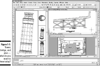
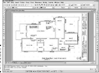
Figure 1-1 shows several kinds of drawings in AutoCAD 2005.
The Importance of Being DWG
To take full advantage of AutoCAD in your work environment, you need to be aware of the DWG file format, the format in which AutoCAD saves drawings. In some cases an older version of AutoCAD can’t open a DWG file that’s been saved by a newer version of AutoCAD.
⻬A newer version of AutoCAD alwayscan open files saved by an older version.
⻬Someprevious versions of AutoCAD can open files saved by the subse-quent one or two versions. For example, AutoCAD 2004 can open DWG files saved by AutoCAD 2005. That’s because Autodesk didn’t change the DWG file format between AutoCAD 2004 and AutoCAD 2005.
⻬You can use the “save as” option in newer versions to save the file to some older DWG formats.
Table 1-1 shows which versions (described later in this chapter) use which DWG file formats.
Table 1-1
AutoCAD Versions and DWG File Formats
AutoCAD Version AutoCAD LT Version Release DWG File Year Format
AutoCAD 2005 (“A2k5”) AutoCAD LT 2005 2004 Acad 2004
AutoCAD 2004 (“A2k4”) AutoCAD LT 2004 2003 Acad 2004
AutoCAD 2002 (“A2k2”) AutoCAD LT 2002 2001 Acad 2000
AutoCAD 2000i (“A2ki”) AutoCAD LT 2000i 2000 Acad 2000
AutoCAD 2000 (“A2k”) AutoCAD LT 2000 1999 Acad 2000
AutoCAD Release 14 (“R14”) AutoCAD LT 98 & 97 1997 Acad R14
AutoCAD Release 13 (“R13”) AutoCAD LT 95 1994 Acad R13
AutoCAD Release 12 (“R12”) AutoCAD LT Release 2 1992 Acad R12
Working with AutoCAD is easier when your co-workers and colleagues in other companies all use the same version of AutoCAD and AutoCAD-related tools. That way, your DWG files, add-on tools, and even the details of your CAD knowledge can be mixed and matched among your workgroup and part-ners. In the real world, you’ll probably work with people — at least in other companies — who use AutoCAD versions as old as Release 14.
Many programs claim to be DWG-compatible— that is, capable of converting data to and from AutoCAD’s DWG format. But achieving this compatibility is a difficult thing to do well. Even a small error in file conversion can have results ranging in severity from annoying to appalling. If you exchange DWG files with people who use other CAD programs, be prepared to spend time finding and fixing translation problems.
Seeing the LT
AutoCAD LT is one of the best deals around, a shining example of the old 80/20 rule: roughly 80 percent of the capabilities of AutoCAD for roughly 20 percent of the money. Like AutoCAD, AutoCAD LT runs on mainstream Windows computers and doesn’t require any additional hardware devices. With AutoCAD LT, you can be a player in the world of AutoCAD, the world’s leading CAD program, for a comparatively low starting cost.
AutoCAD LT is a very close cousin to AutoCAD. Autodesk creates AutoCAD LT by starting with the AutoCAD program, taking out a few features to justify charging a lower price, adding a couple of features to enhance ease of use versus full AutoCAD, and testing the result.
As a result, AutoCAD LT looks and works much like AutoCAD. The opening screen and menus of the two programs are nearly identical. (LT is missing a few commands from the AutoCAD menus.)
AutoCAD-based applications
Autodesk has expanded AutoCAD into a wholeproduct line of programs with AutoCAD as a base and specialized, discipline-specific add-ons built on top and included as one complete product. As an AutoCAD 2005 user, you’ll be looking for the 2005-compatible versions of these tools, which should appear a few months after AutoCAD 2005 ships. These discipline-specific flavors of AutoCAD include Autodesk Architectural Desktop and Autodesk Building Systems (mechanical, electrical, and plumbing), Autodesk Mechanical Desktop, Autodesk Map, AutoCAD Land Desktop, Autodesk Survey, and Autodesk Civil Design.
To make matters even more confusing, Autodesk now offers Autodesk Revit and Autodesk Inventor, software applications that compete with Architectural Desktop and Mechanical
Desktop, respectively. Revit and Inventor are not based on AutoCAD; they sacrifice AutoCAD compatibility in favor of a more fundamentally design- and 3D-oriented approach to CAD. Whether they ultimately will replace the tradi-tional AutoCAD-based applications remains to be seen. Thus far, most companies seem to be sticking with AutoCAD and the AutoCAD-based Desktop applications.
In addition to the products from Autodesk, thou-sands of AutoCAD add-on products — both discipline-specific and general-purpose — are available from other software developers. These companion products are sometimes called third-party applications.Visit partnerproducts. autodesk.com/for more information about
In fact, the major difference between the programs has nothing to do with the programs themselves. The major difference is that AutoCAD LT lacks support for several customization and programming languages that are used to develop AutoCAD add-ons. So almost none of the add-on programs or utilities offered by Autodesk and others are available to LT users.
AutoCAD LT also has only limited 3D support. You can view and edit 3D objects in AutoCAD LT, so you can work with drawings created in AutoCAD that contain 3D objects. However, you cannot create true 3D objects.
The lack of 3D object creation in LT is not as big a negative for many users as you may think. Despite a lot of hype from the computer press and CAD ven-dors (including Autodesk), 3D CAD remains a relatively specialized activity. The majority of people use CAD programs to create 2D drawings.
Although you may hear claims that AutoCAD LT is easier to master and use than AutoCAD, the truth is that they’re about equally difficult (or easy, depending on your nerd IQ). The LT learning curve doesn’t differ significantly from that of AutoCAD. AutoCAD was originally designed for maximum power and then modified somewhat to improve ease of use. AutoCAD LT shares this same heritage.
Fortunately, the minimal differences between LT and AutoCAD mean that after you have climbed that learning curve, you’ll have the same great view. You’ll have almost the full range of AutoCAD’s 2D drafting tools, and you’ll be able to exchange DWG files with AutoCAD users without data loss.
This book covers AutoCAD 2005, but almost all the information in it applies to AutoCAD LT 2005 as well. The icon that you see at the left of this para-graph highlights significant differences. If you’re an LT user, you may want to look for AutoCAD LT 2005 For Dummies, which is aimed squarely at AutoCAD LT and the types of people who use it instead of AutoCAD.
Staying Alive with 2005
You should know this before you upgrade from a previous AutoCAD release:
⻬Wash those old Windows:AutoCAD 2005 does not support older ver-sions of Windows, such as Windows NT, 98, and Me. You must use Windows XP (Professional, Home, or Tablet PC) or Windows 2000.
AutoCAD 2004. You can use File➪Save As to create DWG files for users of AutoCAD 2000, 2000i, and 2002, but not for AutoCAD Release 14 and earlier versions. (To get around this limitation, you can save to the Release 12 DXF format — see Chapter 18 for instructions.)
⻬Application compatibility:If you use third-party applications with a pre-vious version of AutoCAD, they may not work with AutoCAD 2005. Most AutoCAD 2004 applications, including those developed with the ARX (AutoCAD Runtime eXtension) and VBA (Visual Basic for Applications) programming interfaces will work with AutoCAD 2005, but older ARX and VBA applications won’t work.
Many LSP (AutoLISP)programs written for the last several versions of AutoCAD work with AutoCAD 2005.
⻬Increased computer system requirements:For AutoCAD 2005, Autodesk recommends an 800 MHz Pentium III or better processor, at least 256MB of RAM, 1024 x 768 or higher display resolution, 300MB of available hard disk space, an Internet connection, and Microsoft Internet Explorer 6.0 with Service Pack 1 or later.
AutoCAD 2005 comes out a mere year after AutoCAD 2004 and thus doesn’t sport quite as many new features as did some earlier upgrades, many of which came out at two-year intervals. The new features and feature improve-ments in AutoCAD 2005, however, are well conceived and worthwhile. My three favorites are:
⻬Sheet sets — a radically new and much more sophisticated way of orga-nizing sets of drawings. (See Chapter 14.)
⻬Text tables, an enormously improved way to place tabular data on draw-ings quickly and uniformly — including the ability to import the data from Excel spreadsheets. (See Chapter 9.)
⻬An improved plotting interface, including background plotting. (See Chapter 12.)
No Express service?
The AutoCAD 2005 CD-browser screen includesseparate links for installing the main AutoCAD 2005 software and the Express Tools — a set of handy utilities for AutoCAD (but not available for AutoCAD LT). If your menu bar doesn’t include the Express menu shown in Figure 1-1, you
AutoCAD 2005 includes other goodies — look for the icon that you see at the left of this paragraph.
If you’re using any version prior to AutoCAD 2004, the new version definitely is worth upgrading to. You’ll enjoy a slew of improvements, including a cleaner, more functional interface (Chapter 2), numbered and bulleted text lists (Chapter 9), and many xref enhancements (Chapters 13 and 16).
Le Tour de AutoCAD 2005
In This Chapter
䊳Touring the AutoCAD 2005 screen
䊳Going bar-hopping: title bars, the menu bar, toolbars, and the status bar
䊳Commanding the command line
䊳Discovering the drawing area
䊳Making the most of Model and Layout tabs
䊳Dabbling with palettes
䊳Setting system variables and using dialog boxes
䊳Using online help
A
utoCAD 2005 is a full-fledged citizen of the Windows world, with tool-bars, dialog boxes, right-click menus, a multiple-document interface, and all the other trappings of a real Windows program. But lurking beneath that pretty face — and literally beneath the drawing area, right at the bottom of the AutoCAD program window — is a weird but essential holdover from the DOS days: the AutoCAD command line area. The command line is one of the few un-Windows-like things in AutoCAD that you’ll have to come to terms with, and this chapter shows you how.AutoCAD Does Windows
Finding your way around AutoCAD 2005 can be an odd experience. You recog-nize from other Windows applications much of the appearance and workings of the program, such as its toolbars and pull-down menus, which you use for entering commands or changing system settings. But other aspects of the program’s appearance — and some of the ways in which you work with it — are quite different from other Windows programs. You can, in many cases, tell the program what to do in at least four ways — pick a toolbar icon, pick from the pull-down menus, type at the command line, or pick from the right-click menus — none of which is necessarily the best method to use for every task. The experience is much like that of having to act as several different charac-ters in a play; you’re likely to forget your lines (whichever “you” you are at the time!) every now and then.
As with other Windows programs, the menus at the top of the AutoCAD screen enable you to access most of the program’s functions and are the easiest-to-remember method of issuing commands. When you want to get real work done, you’ll need to combine the pull-down menus with other methods — especially typing options at the command line or choosing them from the right-click menu. I show you how throughout this book.
Screen test yields high profile
The screen shots and descriptions in this chapterreflect the default configuration of AutoCAD —
that is, the way the screen looks if you use the standard version of AutoCAD (not a flavored ver-sion such as Architectural Desktop) and haven’t messed with the display settings. You can change the appearance of the screen with settings on the Display tab of the Options dialog box (choose Tools➪Options➪Display) and by dragging tool-bars and other screen components.
The change I’ve made is to configure the draw-ing area background to be white instead of black, because the figures in the book show up better that way. On your system, you’ll probably want to leave your drawing area background black, because the normal range of colors that appears in most drawings is easier to see against a black background.
AutoCAD’s Opening Screen Cuisine
When you launch AutoCAD after first installing it, the opening screen, shown in Figure 2-1, displays an arrangement of menus, toolbars, palettes, and a new, blank drawing. You can close the Sheet Set Manager and Tool Palettes for now — I describe how to turn them back on and how to use them later in this chapter. (If you installed the Express Tools, as I describe at the end of Chap-ter 1, you’ll also see a flock of small toolbars labeled ET. You can safely close all these and use the Express pull-down menu to access all the Express Tools.)
Standard Windows fare
As you see in Figure 2-1, much of the AutoCAD screen is standard Windows fare — title bars, a menu bar, toolbars, and a status bar.
Title bar
Command line area Status bar
Drawing area Menu bar
Toolbars
AutoCAD program's title bar control buttons
Current drawing's control buttons
A hierarchy of title bars
Like most Windows programs, AutoCAD has a title barat the top of its pro-gram window that reminds you which propro-gram you’re in (not that you’d ever mistake the AutoCAD window for, say, Microsoft Word!).
⻬At the right side of the title bar is the standard set of three Windows control buttons: Minimize, Maximize/Restore, and Close.
⻬Each drawing window within the AutoCAD program window has its own title bar. You use the control buttons on a drawing window’s title bar to minimize, maximize/un-maximize, or close that drawing, not the entire AutoCAD program.
As in other Windows programs, if you maximize a drawing’s window, it expands to fill the entire drawing area. (AutoCAD 2005 starts with the drawing maxi-mized in this way.) As shown in Figure 2-1, the drawing’s control buttons move onto the menu bar, below the control buttons for the AutoCAD program win-dow; the drawing’s name appears in the AutoCAD title bar. To un-maximize the drawing so you can see any other drawings that you have open, click the lower un-maximize button. The result is as shown in Figure 2-2: a separate title bar for each drawing with the name and controls for that drawing.
Making choices from the menu bar
The menu barcontains the names of all the primary menus in your version of AutoCAD. As with any program that’s new to you, it’s worth spending a few minutes perusing the menus in order to familiarize yourself with the com-mands and their arrangement. (If your menu bar doesn’t include the Express menu, see the end of Chapter 1 for installation instructions.)
Cruising the toolbars
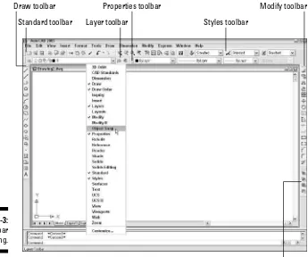
As in other Windows programs, the toolbars in AutoCAD 2005 provide rapid access to the most commonly used AutoCAD commands. AutoCAD ships with toolbars in this default arrangement (as shown in Figure 2-3):
⻬Standard toolbar:Located on top, just below the menu bar; file manage-ment and other common Windows functions, plus some specialized AutoCAD stuff such as zooming and panning.
⻬ Styles toolbar: To the right of the Standard toolbar; analogous to the left part of the Formatting toolbar in Microsoft programs, but formatting of AutoCAD’s text, dimension, and table styles. (Table styles are new in AutoCAD 2005.) Chapters 9 and 10 cover these features.
⻬Layers toolbar:Beneath the Standard toolbar; commands and a drop-down list for manipulating layers, which are AutoCAD’s fundamental tools for organizing and formatting objects. Chapter 4 contains the layer lowdown.
⻬Properties toolbar:To the right of the Layers toolbar; analogous to the right part of the Formatting toolbar in Microsoft programs, but formatting of AutoCAD’s properties, such as colors, linetypes, and lineweights. See Chapter 4 when you’re ready to play with AutoCAD’s object properties.
⻬Draw toolbar:Vertically down the far-left edge of the screen; the most commonly used commands from the Draw menu. Chapter 5 covers most of the items on this toolbar.
Hot-wiring the menu bar
Some standard tips and tricks for Windows areespecially useful in AutoCAD. Control-key short-cuts for the most popular functions — Ctrl+S to save, Ctrl+O to open a file, and Ctrl+P to print — work the same way in AutoCAD as in most other Windows programs. Use them!
Also worth exploring are the Alt-key shortcuts, which are available for all menu choices, not just
⻬Modify toolbar: Vertically down the far-right edge of the screen; the most commonly used commands from the Modify menu. Chapter 8 shows you how to use almost everything on this toolbar.
⻬ Draw Order toolbar:Beneath the Modify toolbar; commands for con-trolling which objects appear on top of which other objects. Chapter 13 mentions these features.
You can rearrange, open, and close toolbars as in other Windows programs:
⻬To move a toolbar, point to its border (the double-line control handle at the leading edge of the toolbar is the easiest part to grab), click, and drag.
⻬To open or close toolbars, right-click on any toolbar button and choose from the list of available toolbars, as shown in Figure 2-3.
The AutoCAD screen in Figure 2-3 shows the default toolbar arrangement, which works fine for most people. Feel free to close the Draw Order toolbar; you aren’t likely to use its features frequently. You may want to turn on a couple of additional toolbars, such as Object Snap and Dimension, as you dis-cover and make use of additional features. Throughout this book, I point out when a particular toolbar may be useful.
Standard toolbar
Draw Order toolbar Draw toolbar
Layer toolbar
Properties toolbar
Styles toolbar
Modify toolbar
If you’re not satisfied with just rearranging the stock AutoCAD toolbars, you can customize their contents or even create new ones. The procedures are beyond the scope of this book; they involve bouncing among the Commands, Toolbars, and Properties tabs on the Customize dialog box in not entirely intuitive ways. Resist slicing and dicing the stock AutoCAD toolbars until you’re at least somewhat familiar with them. If you want to get creative there-after, go to the Contents tab of the AutoCAD 2005 online help and choose Customization Guide➪Basic Customization➪Create Custom Toolbars.
AutoCAD toolbar buttons provide ToolTips,those short text descriptions that appear in little yellow boxes when you pause the cursor over a toolbar button. A longer description of the icon’s function appears in the status bar at the bottom of the screen.
Looking for Mr. Status Bar
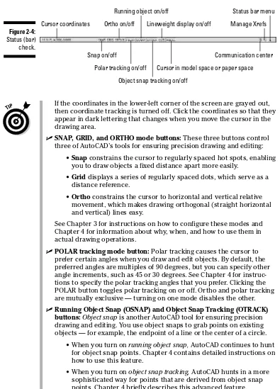
The status barappears at the bottom of the AutoCAD screen, as shown in Figure 2-4. The status bar displays and allows you to change several impor-tant settings that affect how you draw and edit in the current drawing. Some of these settings won’t make complete sense until you’ve used the AutoCAD commands that they influence, but here’s a brief description, with pointers to detailed descriptions of how to use each setting elsewhere in this book:
⻬Coordinates of the cursor:The cursor coordinatesreadout displays the current X,Y,Z location of the cursor in the drawing area, with respect to the origin point (whose coordinates are 0,0,0). It’s a bit like having a GPS (Global Positioning System) device in your drawing. Chapter 4 describes AutoCAD’s coordinate conventions and how to use this area of the status bar.
The toolbars that ET AutoCAD
If you’ve installed the Express Tools, you’ll alsosee a flock of Express Tools toolbars, whose labels begin with “ET:”, floating over the draw-ing area. These four small toolbars collect some of the most popular Express Tools. You’ll proba-bly want to close most of these or at least dock any favorites along the margin of the AutoCAD window.
The toolbars are extensions to AutoCAD, not part of the core program, so turning them on is
If the coordinates in the lower-left corner of the screen are grayed out, then coordinate tracking is turned off. Click the coordinates so that they appear in dark lettering that changes when you move the cursor in the drawing area.
⻬SNAP, GRID, and ORTHO mode buttons:These three buttons control three of AutoCAD’s tools for ensuring precision drawing and editing:
•Snap constrains the cursor to regularly spaced hot spots, enabling you to draw objects a fixed distance apart more easily.
•Grid displays a series of regularly spaced dots, which serve as a distance reference.
•Orthoconstrains the cursor to horizontal and vertical relative movement, which makes drawing orthogonal (straight horizontal and vertical) lines easy.
See Chapter 3 for instructions on how to configure these modes and Chapter 4 for information about why, when, and how to use them in actual drawing operations.
⻬POLAR tracking mode button:Polar tracking causes the cursor to prefer certain angles when you draw and edit objects. By default, the preferred angles are multiples of 90 degrees, but you can specify other angle increments, such as 45 or 30 degrees. See Chapter 4 for instruc-tions to specify the polar tracking angles that you prefer. Clicking the POLAR button toggles polar tracking on or off. Ortho and polar tracking are mutually exclusive — turning on one mode disables the other.
⻬Running Object Snap (OSNAP) and Object Snap Tracking (OTRACK) buttons: Object snap is another AutoCAD tool for ensuring precision drawing and editing. You use object snaps to grab points on existing objects — for example, the endpoint of a line or the center of a circle.
• When you turn on running object snap, AutoCAD continues to hunt for object snap points. Chapter 4 contains detailed instructions on how to use this feature.
• When you turn on object snap tracking,AutoCAD hunts in a more sophisticated way for points that are derived from object snap points. Chapter 4 briefly describes this advanced feature. Cursor coordinates
AutoCAD LT doesn’t include the object snap tracking feature, so you won’t see an OTRACK button on its status bar.
⻬Lineweight (LWT) display mode button:One of the properties that you can assign to objects in AutoCAD is lineweight— the thickness that lines appear when you plot the drawing. This button controls whether you see the lineweights on the screen. (This button doesn’t control whether lineweights appear on plots; that’s a separate setting in the Plot dialog box.) Chapter 4 gives you the skinny (and the wide) on lineweights.
⻬MODEL/PAPER space button:As I describe in the section “Main course: The drawing area” later in this chapter, the drawing area is composed of overlapping tabbed areas labeled Model, Layout1, and Layout2 by default. The Model tab displays a part of the drawing called model space,where you create most of your drawing. Each of the remaining tabs displays a
paper space layout, where you can compose a plotable view with a title block. A completed layout will include one or more viewports, which reveal some or all the objects in model space at a particular scale.
The MODEL/PAPER status bar button (not to be confused with the Model
tab) comes into play after you click one of the paper space layout tabs. The MODEL/PAPER button provides a means for moving the cursor between model and paper space while remaining in the particular layout.
• When the MODEL/PAPER button says MODEL, drawing and editing operations take place in model space, inside a viewport.
• When the button says PAPER, drawing and editing operations take place in paper space on the current layout.
Don’t worry if you find model space and paper space a little disorienting at first. The paper space layout setup information in Chapter 3 and plot-ting instructions in Chapter 12 will help you get your bearings and navi-gate with confidence.
⻬ Maximize/Minimize Viewport button(paper space layouts only): When you’re looking at one of the Layout tabs instead of the Model tab, the status bar displays an additional Maximize Viewport button. Click this button to expand the current paper space viewport so that it fills the entire drawing area. Click the button — now called Minimize Viewport — again to restore the viewport to its normal size. (Chapter 3 describes viewports.)
⻬Communication Center:This button opens a dialog box containing recent AutoCAD-related headlines that Autodesk thinks you may find useful. The headlines are grouped into categories called channels: Live Update Maintenance Patches, Articles and Tips, Product Support Information, and so on. Each headline is a link to a Web page with more information, such as how to download a software update or fix a prob-lem. Click the Settings button to select channels you see in the Communication Center window.
that are incorporated into the current drawing). Chapter 13 tells you how to use xrefs and what the Manage Xrefs button does.
⻬Status Bar Menu:When you click the easy-to-miss downward-pointing arrow near the right edge of the status bar, you open a menu with options for toggling off or on each status bar button. Now you can deco-rate your status bar to your taste.
You can open dialog boxes for configuring many of the status bar button functions by right-clicking the status bar button and choosing Settings. Chapters 3 and 4 give you specific guidance about when and how to change these settings.
A button’s appearance shows whether the setting is turned on or off. Depressed, or down, means on; raised, or up, means off. If you’re unclear whether a setting is on or off, click its button; its mode will change and the new setting will be reflected on the command line — <Osnap off>, for exam-ple. Click again to restore the previous setting.
Take an order: The command line area
If the title bars, menu bar, and status bar are the Windows equivalent of com-fort food — familiar, nourishing, and unthreatening — then the command line area, shown in Figure 2-5, must be the steak tartare or blood sausage of the AutoCAD screen feast. It looks weird, turns the stomachs of newcomers, and delights AutoCAD aficionados. The hard truth is that you have to come to like — or at least tolerate — the command line if you want to become at all comfortable using AutoCAD.
You need to get up close and personal with the command line for four reasons:
⻬The command line area is AutoCAD’s primary communications con-duit with you.This is the most important reason to pay attention to the command line. AutoCAD frequently displays prompts, warnings, and error messages in the command line area. If you don’t keep an eye on this area, you’ll miss a lot of vital information. You’ll continually be frus-trated, because you won’t “hear” what AutoCAD is trying to tell you.
⻬The command line is an efficient way to run some commands and the only way to run a few others. Instead of clicking a toolbar button or a Figure 2-5:
menu choice, you can start a command by typing its command name and then pressing the Enter key. Even better, you can type the keyboard short-cut for a command name and press Enter. Most of the keyboard shortshort-cuts for command names are just one or two letters — for example, L for the LINE command and CP for the COPY command. Most people who dis-cover how to use the shortcuts for the commands that they run most fre-quently find that their AutoCAD productivity improves noticeably. Even if you’re not worried about increasing your productivity with this technique, there are some commands that aren’t on the toolbars or pull-down menus. If you want to run those commands, you have to type them!
⻬After you’ve started a command — whether from a toolbar, from a menu, or by typing — the command line is where AutoCAD prompts you with options for that command.
You activate one of these options by typing the uppercase letter(s) in the option and pressing Enter.
In many cases, you can activate a command’s options by right-clicking in the drawing area and choosing the desired option from the right-click menu, instead of by typing the letter(s) for the option and pressing Enter. But if you don’t watch the command line, you probably won’t real-ize that there areany options!
⻬You sometimes need to type coordinates at the command line to specify precise points or distances.Chapter 4 describes this technique in detail.
You don’t have to click in the command line area to type command names, keyboard shortcuts, or command options there. AutoCAD knows that your typing is supposed to go to the command line. The only exception is when you’re within a text command (you’re adding a text note to the drawing itself); in that case, the text appears in the drawing, not in the command line area.
The following sequence demonstrates how you use the command line area to run commands, view and select options, and pay attention to messages from AutoCAD:
1. Type Land press Enter.
AutoCAD starts the LINE command and displays the following prompt in the command line area:
LINE Specify first point:
2. Click a point anywhere in the drawing area.
The command line prompt changes to:
Specify next point or [Undo]:
3. Click another point anywhere in the drawing area.
AutoCAD draws the first line segment.
4. Click a third point anywhere in the drawing area.
AutoCAD draws the second line segment. The command line prompt changes to:
Specify next point or [Close/Undo]:
AutoCAD now displays two options, Close and Undo, separated by a slash.
5. Type Uand press Enter.
AutoCAD undoes the second line segment.
6. Type 3,2(without any spaces) and press Enter.
AutoCAD draws a new line segment to the point whose the X coordinate is 3 and the Y coordinate is 2.
7. Click several more points anywhere in the drawing area.
AutoCAD draws additional line segments.
8. Type Xand press Enter.
AutoCAD displays an error message (because X isn’t a valid option of the LINE command) and reprompts for another point:
Point or option keyword required. Specify next point or [Close/Undo]:
Option keyword is programmer jargon for the letter(s) shown in upper-case that you type to activate a command option. This error message is AutoCAD’s way of saying “I don’t understand what you mean by typing ‘X.’ Either specify a point or type a letter that I do understand.”
9. Type Cand press Enter.
AutoCAD draws a final line segment, which creates a closed figure, and ends the LINE command. The naked command prompt returns, indicat-ing that AutoCAD is ready for the next command:
Command:
10. Press the F2 key.
AutoCAD displays the AutoCAD Text Window, which is simply an enlarged, scrollable version of the command line area, as shown in Figure 2-6.
The normal three-line command line area usually shows you what you need to see, but occasionally you’ll want to review a larger chunk of com-mand line history (“what was AutoCAD trying to tell me a minute ago?!”).
11. Press the F2 key again.
Here are a few other tips and tricks for using the command line effectively:
⻬ Use the Esc key to bail out of the current operation. There will be times when you get confused about what you’re doing in AutoCAD and/or what you’re seeing in the command line area. If you need to bail out of the current operation, just press the Esc key one or more times until you see the naked command prompt — Command:at the bottom of the command line area, with nothing after it. As in most other Windows programs, Esc is the cancel key. Unlike many other Windows programs, AutoCAD keeps you well informed of whether an operation is in progress. The naked command prompt indicates that AutoCAD is in a quiescent state, waiting for your next command.
⻬Press Enter to accept the default action. Some command prompts include a default action in angled brackets. For example, the first prompt of the POLygon command is
Enter number of sides <4>:
The default here is four sides, and you can accept it simply by pressing the Enter key. (That is, you don’t have to type 4first.)
AutoCAD uses two kinds of brackets in command line prompts.
• Command options appear in regular brackets: [Close/Undo].
To activate a command option, type the letter(s) that appear in uppercase and then press Enter.
• A Default value or option appears in angled brackets: <>.
To choose the default value or option, simply press Enter.
⻬Observe the command line. You’ll discover a lot about how to use the command line simply by watching it after each action that you take. When you click a toolbar button or menu choice, AutoCAD types the name of the command automatically, so if you’re watching the command line, you’ll absorb the command names more-or-less naturally.
When AutoCAD types commands automatically in response to your tool-bar and menu clicks, it usually adds one or two extra characters to the front of the command name.
• AutoCAD usually puts an underscore in front of the command name (for example, _LINE instead of LINE). The underscore is an Autodesk programmers’ trick that enables non-English versions of AutoCAD to understand the English command names that are embedded in the menus.
• AutoCAD sometimes puts an apostrophe in front of the command name and any underscore (for example, ‘_ZOOM instead of ZOOM). The apostrophe indicates a transparentcommand; you can run the command in the middle of another command without canceling the first command. For example, you can start the LINE command, run the ZOOM command transparently, and then pick up where you left off with the LINE command.
⻬Leave the command line in the default configuration initially. The com-mand line area, like most other parts of the AutoCAD screen, is resizable and relocateable. The default location (docked at the bottom of the AutoCAD screen) and size (three lines deep) work well for most people. Resist the temptation to mess with the command line area’s appearance — at least until you’re comfortable with how to use the command line.
⻬Right-click in the command line area for options. If you right-click in the command line area, you’ll see a menu with some useful choices, including Recent Commands — the last six commands that you ran.
⻬Press the up- and down-arrow keys to cycle through the stack of com-mands that you’ve typed recently. This is another handy way to recall and rerun a command. Press the left- and right-arrow keys to edit the command line text that you’ve typed or recalled.
Main course: The drawing area
Most of this book shows you how to interact with the drawing area, but you should know a few things up front.
The Model and Layout tabs (Model and Paper Space)
One of the initially disorienting things about AutoCAD is that finished draw-ings can be composed of objects drawn in different spaces, which AutoCAD indicates with the tabs along the bottom of the drawing area (Model, Layout1, and Layout2 by default).
⻬Model spaceis where you create and modify the objects that represent things in the real world — walls, widgets, waterways, or whatever.
⻬Paper spaceis where you create particular views of these objects for plotting, usually with a title block around them. Paper space comprises one or more layouts, each of which can contain a different arrangement of model space views and different title block information.
When you click the Model tab in the drawing area, you see pure, unadulterated model space, as shown in Figure 2-7. When you click one of the paper space layout tabs (Layout1 or Layout2, unless someone has renamed or added to them), you see a paper space layout, as shown in Figure 2-8. A completed layout usually includes one or more viewports, which are windows that display all or part of model space at a particular scale. A layout also usually includes a title block or other objects that exist only in the layout and don’t appear when you click the Model tab. (Think of the viewport as a window looking into model space and the title block as a frame around the window.) Thus, a layout dis-plays model space and paper space objects together, and AutoCAD lets you draw and edit objects in either space. See Chapter 3 for information about cre-ating paper space layouts and Chapter 12 for the lowdown on plotting them.
As I describe in the “Looking for Mr. Status Bar” section in this chapter, after you’ve clicked one of the layout tabs, the status bar’s MODEL/PAPER button
AutoCAD is no vin ordinaire
The back and forth needed to get AutoCAD todraw and complete a line is a great example of AutoCAD’s power — and its power to confuse new users. It’s kind of like a wine that tastes a bit harsh initially, but that ages better than something more immediately drinkable. In other programs, if you want to draw a line, you just draw it. In AutoCAD, you have to press Enter one extra time when you’re done just to tell AutoCAD you really are finished drawing.
But the fact that the Line command remains active after you draw the first line segment makes it much faster to draw complicated, multisegment lines, which is a common activity in a complex drawing.
moves the cursor between model and paper space while remaining in the particular layout. (As shown in Figures 2-7 and 2-8, the orientation icon at the lower-left corner of the AutoCAD drawing area changes between an X-Y axis for model space and a drafting triangle for paper space as an additional reminder of which space the cursor currently resides in.) Chapter 3 describes the consequences of changing the MODEL/PAPER setting and advises you on how to use it.
This back-and-forth with the MODEL/PAPER button or double-clicking is nec-essary only when you’re drawing things while viewing one of the paper space layouts. In practice, you probably won’t encounter that situation very often. Instead, you’ll do most of your drawing on the Model tab and, after you’ve set up a paper space layout, click its layout tab only when you want to plot.
Drawing on the drawing area
Here a few other things to know about the AutoCAD drawing area:
⻬Efficient, confident use of AutoCAD requires that you continually glance from the drawing area to the command line area (to see those all-important prompts!) and then back up to the drawing area. This sequence is not a natural reflex for most people. Get in the habit of looking at the command line after each action that you take, whether picking something on a toolbar, on a menu, or in the drawing area.