Teen-Size Humanoid “FLoW” Complete Analytical Kinematics
Luky Yanto, Raden Sanggar Dewanto, Dadet Pramadihanto, Eko Henfri Binugroho
Politeknik Elektronika Negeri Surabaya (PENS)
Kampus PENS, Jalan Raya ITS Sukolilo, Surabaya,60111 Indonesia Telp: +62-31- 594 7280; Fax: +62-31- 594 6114
Email : [email protected], {sanggar, dadet, sragen }@pens.ac.id
Abstract
Humanoid research in Indonesia is quite a lot, but in reality only limited in kid-size proportional size, while for the Teen-Size is still rare. Research on the Teen-Size Humanoid robot requires more joints to be able to perform the movement compared to the size of Kid-Size, therefore required more complex modeling to determine the movement. With complete kinematics anlysis, the movement of the robot can be solved. With kinematic forward-invers, researchers can determine the movement of robots by controlling the motor parts that function as a joint on the robot. In this study, the modeling uses D-H parameter, because this modeling has been widely used, besides the calculation can be solved by computing. And then for the simulation can be done with V-REP software. Forward-invers kinematics can be implemented on the PID algorithm, in order to generate speed on the motor that can form an angle on the motor to make the movement. The result of this research is to obtain equation of matrix transformation from all body parts of robot. With the creation of this Humanoid Teen-Size robot, it is hoped that the research on Humanoid robot in Indonesia will be increasingly diverse and increasing, and can be used as a support and reference in the development of Humanoid Teen-Size next.
Keywords: Humanoid Robot, Humanoid Teen-Size, D-H Parameters, Total Kinematics.
1. INTRODUCTION
Research on humanoid robot in Indonesia has many, but only limited to Kid-Size size. While research on the size of Teen-Size is still rare. This encourages researchers and teams to develop research on the humanoid robot size Teen-Size called "FLoW" This robot has a height of 110 cm and weighs 12.5 kg. FLOW robot has several basic parts, such as eyes, head, neck, body, hands and feet. In designing a robot, it takes a kind of mathematical modeling that is used in controlling the movement of robots.
The purpose of this study is to analyze the movement of the robot to the point of reference that is still or moving without regard to the force that causes the movement. To organize the movement of robots regardless of the style and geometric aspects of the robot, Inverse kinematics and kinematics forward are indispensable for solving robotic kinematic control systems. Inverse kinematics describes the configuration of the position of the joints to produce the position and orientation of motion of motors that form a certain angle, whereas forward kinematics describes the position and orientation of the speed movement of the motor that forms the position of an angle.
The benefit of this research is to provide the acquisition of a mathematical model. This mathematical model is derived from the robotic kinematic equation. Furthermore, this kinematics model will be used to control the movement of humanoid robot "FLoW" Teen-Size.
2. RELATED WORKS
The research is similar to Nikos Kofinas, Emmanouil Orfanoudakis, and Michail G. Lagoudakis [7]. In their study, researchers conducted research on the kinematics of the entire body that existed on the NAO robot. In this study they also used the Denavit - Hartenberg (DH) Parameter approach. Using the DH approach will be known the transformation model of the NAO robot parts, such as head, hands, torso, and legs.
In a study conducted by Robyarta Haruli Ruci and Bayu Arengga, researchers also performed a kinematics analysis that was applied to the foot of the Bipedal FLoW robot [4]. In this study the researchers also used DH and geometry approaches to complete the kinematics model of the robot legs.
Mupad in Matlab software, then to simulate the researcher using V-REP simulation software. After the matrix transformation of the robot is known, which is the output of the kinemtika modeling of the robot. Furthermore, the result of matrix transformation is inputted through the existing program in V-REP simulation software.
4. SYSTEM DESIGN
This research was made on virtual robot simulation, V-REP based integration of development enviroment on distributed control architecture. This software uses 3 physic engines commonly used in game engines, such as Bullet Engine, Open Dynamic Engine (ODE) and Vortex Engine. So that in every model / object can be controlled using embedded script, plugin, ROS node, and API Client which facilitate the control to be flexible and ideal as in the original system. To control the robot, a mathematical model is needed to form of movement on the robot. The modeling was obtained from the DH Parameter equation on the calculation result using mupad in matlab software.
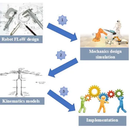
The design and modeling of the simulation in this study are shown in the system design section as shown in Figure 1 below :
Fig. 1. Design System
an addition to the rigid body so that every part of the rigid is not separated between one rigid body to another rigid body.
Then to do the calculation of mathematical modeling can be solved with mupad that exist in Matlab software. To performing calculations on mupad, the parameters of DH must be considered. It is like how the position of the coordinates frame to its global coordinate position. After obtaining the models, the results can be applied to the simulation in V-REP software.
4.1. Simulation Design
Making this model is done in accordance with the existing system design in Figure 1. The section consists of several processes, including the following:
4.1.1. Modeling Object 3D
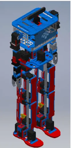
Robot modeling can be done with 3D CAD software using Autodesk Inventor. The robot design consists of a whole body of robot. This parts consist of legs, body, hands and head. The model of the robot as a whole that is designed in Inventor software can be seen as in Figure 2 below:
4.1.2. Import 3D Object
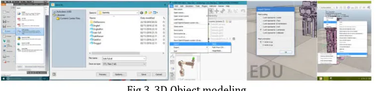
The next step is export 3D object model from Inventor. 3D designs that have the *.ipt extension exported to V-REP, this files with *.stl format from the file menu in the Inventor software. Furthermore, the result file format, which is *.stl imported into enviroment V-REP [8].
Fig 3. 3D Object modeling
4.1.3. V-REP Enviroment Adjustment
At this stage some adjustment steps are made so that a virtual robot environment on V-REP can be formed. These stages include the *.stl files imported into V-REP, the robot size comparison to be used, the grouping of robotic parts based on the rigid body, shape adjustments and joint adjustments in the virtual robot environment.
4.2. Kinematics Robot
In this project, the Hip of the robot has 4 degrees, which is at the waist consists of 2 DoF, and there are 2 DoF on the hip as foot movers. Then the robot's legs have 8 DoFs with parallel shapes, each of which can be assumed as a parallelogram to simplify the analysis. Body that covers the body and head, has 3 DoF, 1 DoF on the waist and 2 DoF on the head. Then on the Arm robot has 7 DoF [9].
To complete this kinematics design, basic knowledge of the homogeneous transformation matrix & Denavit-Hartenberg parameter convention system is required. Further kinematics design can be done with the following steps :
4.2.1. Labeling Joint Angle
The first thing to do simplify the analysis are given the x, y, and z axes on each joint using the right hand rule. For more details, as shown in Figure 4.
Gambar 4. Labeling Joint Angle
4.2.2. Determination of Coordinate Frame to Each Joint
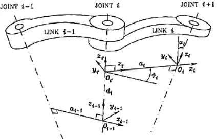
state as shown in Figure 5. In Figure. 5 is an example of determining the coordinates of frames with illustrations when Zi-1 parallel and joint i are swivel joints revolute).
Fig. 5. Denavit-Hartenberg convention
4.2.3. Determination of the Denavit-Hartenberg Convention Table
After determining the coordinates of the frame and its parameters, then from the parameters already known in Figure. 5 are included in a table ai, αi, and θi as in Table 1. Where ai represents the distance along Xi in θi to θi + 1 intersection, distance along Zi-1 from θi-1 to θi intersection, where in is variable if the joint is translational (prismatic). Then αi is the angle between Zi-1 and Zi against the Xi axis. Then for θi denotes the angle between Xi-1 and Xi against the Zi-1 axis, where θi is a variable if the joint is revolute.
Tabel 1. Tabel DH
4.2.4. Transformation Matrix
Substitution of parameters ai, di, αi and θi into the homogeneous transformation matrix equation as shown in Equation. Then multiplication of all homogeneous transformation matrices to obtain forward kinematics. which determines the position and orientation of the tip toward the EoF.
Then the multiplication of this homogeneous matrix has vectors relative to the principal axis which can be described in equation (2) below:
= (2)
Where :
n = vector axis direction OnXn to O0X0Y0Z0 (normal) s = vector axis direction OnYn to O0X0Y0Z0 (sliding) a = vector axis direction OnZn to O0X0Y0Z0 (approach) d = vector shift On to O0 (translasi)
5. EXPERIMENT AND ANALYSIS
This section on humanoid robot modeling is divided into two parts: Upper Body and Down Body. On the Upper Body covers the head, body and hands. Then on the Down Body covers the plates, legs, and angkle. Here are the modeling results from those sections:
5.1. Upper Body
In this section covers the head and hands. At the head of the robot has 2 DoF, while for the hand has 6 DoF. In analyzing kinematics, the first thing to do is to model the joints (motor) on the robot with the rules specified in the D-H Parameters. Here in Figure 6 is a modeling picture of every motor possessed by robots on the upper body parts.
(a) (b)
Fig 6. Modeling kinematics upper body robot
5.2. Down Body
Fig. 7. Down kinematics down body modeling
From Figures 6 and 7, the following parameters will be obtained for the kinematics analysis to be discussed in the results of the analysis below.
Forward Kinematics
Forward kinematics (advanced kinematics) refers to the use of kinematic equations of the robot to calculate the position of the end effector of the value set for the parameters together. Forward kinematics defines the mapping of the space joint to the 3-dimensional Cartesian space [5]. This kinematics equation is applied in many fields of robotics. Although widely applied to the field of robotics, but did not rule out to be applied to computer games and animations related to the motion. Output on the kinematics forward position of O, X, Y, Z on each robot joint.
Invers Kinematics
Invers kinematics. [5] This equation is used to determine the angular value of each joint from the predefined coordinate position of the end effector. Invers is used to specify the parameter values of shared parameters that give the desired position of the end effector. So by using inverse kinematics can be known the amount of angle of movement of the robot joints.
(1) The head of the robot has 2 DoFs that can move in a manner pitch and yaw.
0T3 = 0T1 1T2 (3)
0T3= (4)
Px = (5)
Py = (6)
Pz = 2(d11+d12) (7)
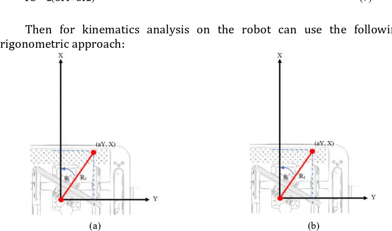
Then for kinematics analysis on the robot can use the following trigonometric approach:
(a) (b)
Fig. 8. (a) The head diagram top view. (b) The head diagram side view
In Fig. 8 is a robot head modeling diagram that is represented when viewed from above. From the figure can be known kinematic inverse equation by using approach of triangle geometry, that is:
θ1 = (8)
θ2 = (9)
0T5 = 0T1 1T2 2T33T44T5 (10)
0T5= (11)
Px = (12)
Py = (13)
Pz = (14)
Then for kinematics analysis on the robot can use the following trigonometric approach:
Fig. 9 The hand diagram top view
In Fig. 9 is a robot hand modeling diagram that is represented when viewed from above. From the figure can be known kinematic inverse equation by using approach of triangle geometry, that is:
(15)
(16)
(a) (b)
Fig. 10 (a) The hand diagram side view (b) The hand diagram front view
θ4 = (18)
θ5 = θ3 + θ4 (19)
(3)The foot section has 5 DoFs that represent hand movements as in humans.
0T6 = 0T1 1T2 2T33T44T55T6 (20)
0T6= (21)
Px = (22)
Py = (23)
Pz = (24)
Fig. 11 Top foot diagram view
In Fig. 11 is a robot head modeling diagram that is represented when viewed from above. From the figure can be known kinematic inverse equation by using approach of triangle geometry, that is:
= Orientasi (25)
R0 = (26)
β = (27)
aY = (28)
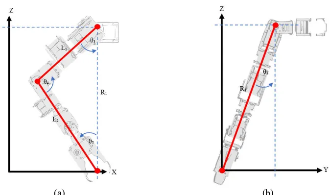
(a) (b)
Fig. 12 (a) The side foot diagram. (b) Front foot diagram
R2 = (30)
θsc = (31)
θsc = (32)
θ2 = (33)
θsb = (34)
Then from equations (30) through (34) for the other angles can be found by the equation:
= (35)
= (36)
= (37)
6. CONCLUSION
This paper presents a complete analysis of the Humanoid Teen FLoW robot on forward and inverse kinematics. Benefits derived from this discussion is to solve the problem of control on the robot, so that with this kinematics modeling solution can be applied to the robot program in forming a desired motion and path.
Acknowledgements
Firstly, I would like to thank the lecturers who always provide knowledge, support and lessons to me. Secondly, I would like to thank the EEPIS for providing facilities. Thirdly, I would like to thank the group of researcher in the EEPIS Robot Research Center (ER2C) and do not forget to thank for my parents who always give a prayer for the success of my robot," in IEEE International Conference, Leuven, 1998.
[3] T. B. a. H. U. S. Lohmeier, "System Design and Control of Anthropomorphic Walking Robot LOLA," IEEE/ASME Transactions on Mechatronics, vol. 14, pp. 658-666, Dec. 2009.
[4] B. A. P. D. P. E. H. B. a. R. S. D. R. H. Ruci, "FLoW bipedal robot: Hula hoop motion," 2015 International Conference on Control, Electronics, Renewable Energy and Communications (ICCEREC), pp. 136-141., 2015. [5] R. S. H. a. J. Denavit, Kinematic synthesis of linkages, Dallas:
McGraw-Hill Inc., 1964.
[6] R. N. Jazar, Theory of applied robotics: kinematics, dynamics, and control, Springer Science & Business Media, 2010..
[7] N. KOFINAS, E. ORFANOUDAKIS and M. G. LAGOUDAKIS, "Complete analytical inverse kinematics for NAO," 2013 13th International Conference on. IEEE, pp. 1-6, 2013.
[8] C. Robotics, 2015, “V-REP” , http://www.copelia-robotic.com, diakses pada tanggal 21 Juni 2016.