CO2 reforming of methane (CORM) to produce
synthesis gas has drawn much interest in recent years because it consumes methane and carbon dioxide which are both major contributors to the green house gases. Moreover, the availability of methane (which is the major component in natural gas) has also encouraged development of this process [1]. The CORM is a catalytic process which
!"#
$!
%& '&
(
#
&(
#
#
$&(
)
*
+
$&! " # $ %&'(%
' ) " * " + " # , - . / &
," "
-* Corresponding Author.
Telp: (+62+24+7460058); Fax.: (+62+24+76480675); Email: [email protected] (I. Istadi)
+ 0 & - '& 1 + 0 2 3" " '& 1 3 0 '( 3" " '&
#
Major problem in CO2 reforming of methane (CORM) process is coke formation which is a carbonaceous
residue that can physically cover active sites of a catalyst surface and leads to catalyst deactivation. A key to develop a more coke+resistant catalyst lies in a better understanding of the methane reforming mecha+ nism at a molecular level. Therefore, this paper is aimed to simulate a micro+kinetic approach in order to calculate coking rate in CORM reaction. Rates of encapsulating and filamentous carbon formation are also included. The simulation results show that the studied catalyst has a high activity, and the rate of carbon formation is relatively low. This micro+kinetic modeling approach can be used as a tool to better understand the catalyst deactivation phenomena in reaction via carbon deposition. Copyright © 2011 BCREC UNDIP. All rights reserved.
: CO2 reforming of methane; CORM; Ni/CaO+Al2O3; coke formation; micro+kinetic modeling;
simulation
: I. Istadi, D.D. Anggoro, N.A.S. Amin, and D.H.W. Ling. (2011). Catalyst Deactivation Simula+ tion Through Carbon Deposition in Carbon Dioxide Reforming over Ni/CaO+Al2O3 Catalyst. 4"
+ 5 , 6 (2): 129+136
involves the indirect utilization of methane and carbon dioxide to produce valuable synthesis gas. Utilization of this process will bring both economic and environmental benefits.
The main reaction for the production of synthesis gas via CORM reaction is given in Equation 1. The CORM reaction is usually accompanied by the simultaneous occurrence of the Reverse Water+Gas Shift reaction (RWGS) as written in Equation 2. However, the critical problem in this process is catalyst deactivation caused by carbon deposition (coking). Basically, there are two types of carbon formation in this reaction, i.e. encapsulating carbon and filamentous
!"
#
$ #
%
&%''#
(
) &( ( )
carbon (Figure 1). Therefore, in order to create a more stable catalyst for CORM, great attention has been focused on development of coke+resistant catalysts. Besides that, cost factor is also important to be considered if the catalyst will be applied industrially.
CH4 + CO2 ↔ 2CO + 2H2 (∆H0298K = +247 kJ/mol)
(1) CO2 + H2 ↔ CO + H2O (∆H0298K = +41 kJ/mol)
(2) During last several years, great efforts have been focused on development of catalysts for this process incorporating a kinetic inhibition of carbon formation under conditions where deposition is thermodynamically favorable. Nickel+based catalysts and noble metal+supported catalysts such as Rh, Ru, Pd, Pt and Ir were found to have promising catalytic performance in terms of conversion and selectivity for the CORM process. According to results by Wang et al. [3], noble metal+based catalysts have shown to have high activity and less sensitive to coking compared to the Ni+based catalysts for the CORM process. In spite of this, high cost and limited availability of noble metals prevent the commercial use for this reaction. Therefore, it is more practical to develop improved Ni+based catalysts which exhibit stable operation for a long period of time.
In order to increase the stability of supported Ni catalysts, some elements were added acting as support modifiers or promoters. According to some experimental researches, it has been proven that the support type and presence of the modifiers greatly affect the coking tendency. According to Ferreira+Aparicio et al. [4] who prepared and tested two series of transition metals (Co, Ni, Ru, Rh, Ir, Pt)+based catalysts using silica and alumina in the CORM reaction, it was shown that alumina+based catalysts show higher specific activity than their respective counterparts dispersed on silica. According to Quincoces et al. [5], CaO+modified Ni catalysts present high stability and good activity with respect to Ni/Al2O3. When CaO is added to the
support, the formation of filamentous carbon decreases and favors the formation of more reactive carbonaceous species. Recent simulation on catalyst deactivation due to coke formation was done by Chigada and co+workers [6]. They suggested that long+range heterogeneities in the pore structure of the catalyst are important for determining deactivation behavior, and the
experimental system involved a series deactivation scheme for the reaction under supercritical conditions. A comparison of simulation with experiment has enabled a validation of the structural model and particular reaction scheme used in the simulations.
In actual fact, the key to develop a more coke+ resistant catalyst lies in a better understanding of the methane reforming mechanism at a molecular level [7]. Micro+kinetic analysis is an examination of catalytic reactions in terms of elementary chemical reactions that occur on the catalytic surface and their relation with each other and with the surface during a catalytic cycle. Micro+kinetics has, for the most part, focused on analysis for understanding the reaction mechanism. It has been shown that micro+kinetic modeling based on knowledge about elementary steps and their energetics, is a very powerful tool for a detailed understanding of catalytic processes [8]. This paper is aimed to simulate a micro+kinetic approach in order to calculate coking rate in CORM reaction. Rates of encapsulating and filamentous carbon formation are also included in this study.
$ , ,
First step in this research was to study the micro+kinetic model of methane reforming on Ni catalysts developed by Aparicio [9]. The micro+ kinetic model consists of adsorption and desorption steps of all reactants and products and the surface elementary reaction steps. The combined reaction for the main CORM reaction and the side RWGS
!! !"
reaction is:
2 CO2 + CH4 ↔ 3 CO + H2 + H2O (3)
The reactions steps for both main and RWGS reactions are combined and they are presented in Table 1 [9]. For each step in the model, the reaction rates for forward and backward reactions are written. It is assumed that the reaction steps are elementary, and the rates are written in terms of partial pressure and surface species. This rate is calculated as turnover frequency. Table 2 shows the reaction rates for all the steps (Equations 4 + 24). The next step in this research was to write the mathematical models in terms of rate of reaction for all the ten surface species and five gaseous species. The differential equations against time is written for each of the surface species namely *CH3, *CH2, *CH, *C, *H2O, *OH, *CHO, *CO, *H
and *, and also the partial pressures for five gaseous species CH4, CO2, H2O, H2 and CO. The
fifteen differential equations of surface species are then solved simultaneously to obtain the fraction of sites occupied by each surface species. The site coverage of adsorbed carbon would then be used to calculate the rate of coking. The fifteen differential equations are presented in Table 3 (Equations 25 + 39).
In this model, it is assumed that the atomic carbon on the surface is a common intermediate in both the main reaction and the carbon formation including filamentous and encapsulating carbon. According to Chen et al. [7], the reaction between the adsorbed carbon on the surface is assumed to be reversible and the sole pathway for encapsulating carbon formation, as shown in Equation 40 [6].
n **C → n Cp (40)
Therefore, the rate for encapsulating carbon formation is given in Equation 41 [7].
rcp = kp θcn (41)
The weight of encapsulating carbon is given in Equation 42:
Cp = rcp . dt . 12 (42)
The site coverage of encapsulating carbon is calculated from Equation 43 [8]:
(43)
According to Froment [9], the filamentous carbon formation involves the following process:
(a) Dissolution of adsorbed+carbon through Ni:
**C ↔ CNi,f (44)
(b) Diffusion of carbon through Ni:
CNi,f ↔ CNi,r (45)
(c) Precipitation / Dissolution of carbon:
CNi,r ↔ Cf (46)
The adsorbed surface carbon, **C, at first dissolves in the Ni particle, therefore it diffuses and precipitates at rear of the nickel crystallite. The continuous precipitation of this adsorbed carbon will form filamentous carbon. For this process to take place, the carbon concentration in the layer just below the Ni surface, CNi,f must
exceed the carbon solubility in Ni, Csat. The higher
the difference between CNi,f and Csat, the bigger
the driving force for this process of filamentous carbon formation.
A simple Langmuir equation was used to estimate the concentration of carbon in the segregation layer is given in Equation 47 [7].
(47)
This equation is used to calculate the weight fraction of carbon in the segregation layer, xb. The
values of θc are obtained from the simulation
results. The value of θc needs to be divided by 2, as
one carbon atom occupies two active sites on the catalyst.
Equation 48 is used to calculate the Gibbs energy for the segregation layer in this process [7]:
OGseg = +10800 – 3.4T (cal/mol) (48)
!! !"
Reaction steps for the combined reaction [9]
. /
CH4 + 2* → *CH3 + *H 2.02 x 10⁶ 53. 9
*CH3 + *H → CH4 + 2* 2.50 x 1010 95.9
*CH3 + * → *CH2 + *H 1 x 10¹³ 115.4
*CH2 + *H → *CH3 + * 2 x 10¹² 75.4
*CH2 + * → *CH + *H 1 x 10¹³ 102.9
*CH + *H → *CH2 + * 2 x 10¹² 75.4
*CH + 2* → **C + *H 1 x 10¹³ 0
**C + *H → *CH + 2* 1.54 x 1011 64.4
2 [ CO2 + 2*H + 2* → **CHO + OH* + * ] 9.97x10⁶ (1/T)0.968 +50.0
2 [ **CHO + OH* + * → CO2 + 2*H + 2* ] 2.9 x 10¹⁵ 0
3 [ **CHO + * → **CO + *H ] 5.14 x 10¹⁹ 0
3 [ **CO + *H → **CHO + * ] 1 x 10⁷ 23.0
3 [ **CO → CO + 2* ] 5 x 10¹² 115.0
3 [ CO + 2* → **CO ] 1 x 10⁸ 0
2*H → H2 + 2* 1 x 1013 95.0
H2 + 2* → 2*H 3 x 10⁸ 0
**C + *OH → **CHO + * 3 x 10¹⁴ 65.5
**CHO + * → **C + *OH 1.13x10²¹(1/T)3.03 90.3
*H + *OH → *H2O + * 3.08 x 10¹¹ 32.2
*H2O + * → *H + *OH 4.15 x 10⁷ 0
*H2O → H2O + * 1 x 10¹³ 64.4
H2O + * → *H2O 1.78 x 10⁶ 0
$ Reaction rates for all the steps
/0 "
1 CH4 + 2* → *CH3 + *H R1 = k1PCH4 θ*2 (4)
2 *CH3 + *H → CH4 + 2* R2 = k2θCH3θH (5)
3 *CH3 + * → *CH2 + *H R3 = k3θCH3θ * (6)
4 *CH2 + *H → *CH3 + * R4 = k4θCH2θH (7)
5 *CH2 + * → *CH + *H R5 = k5θCH2θ* (8)
6 *CH + *H *CH2 + * R6 = k6θCHθH (9)
7 *CH + 2* → **C + *H R7 = k7θCHθ*2 (10)
8 **C + *H → *CH + 2* R8 = k8θCθH (11)
9 2 [ CO2 + 2*H + 2*….→ **CHO + OH* + *] R9 = k9PCO2θH2θ*2 (12)
10 2 [ **CHO + OH* + * → CO2 + 2*H + 2* ] R10=k10θCHOθOHθ* (13)
11 3 [ **CHO + * → **CO + *H ] R11 = k11θCHOθ* (14)
12 3 [ **CO + * H → **CHO + * ] R12 = k12θCOθH
13 3 [ **CO→ CO + 2* ] R13 = k13θCO (15)
14 3 [ CO + 2* → **CO ] R14 = k14PCOθ*2 (16)
15 2*H → H2 + 2* R15 = k15θH2 (17)
16 H2 + 2* → 2*H R16 = k16PH2θ*2 (18)
17 **C + *OH → **CHO + * R17 = k17θCθOH (19)
18 **CHO + * → **C + *OH R18 = k18θCHOθ* (20)
19 *H + *OH → *H2O + * R19 = k19θHθOH (21)
20 *H2O + * → *H + *OH R20 = k20θH2Oθ* (22)
21 *H2O → H2O + * R21 = k21θH20 (23)
!! !""
% Rate equations for surface species and gaseous species
/0 "
/dt
dθ
H R1+R2+R3+R4+R5+R6+R7+R8+4(R9)+4(R10)+3(R11)+3(R12)+(R15)+2(R16)+R19+R20
(25)
/dt
dθ
3
CH
R1+R2+R3+R4 (26)
/dt
dθ
2
CH
R3+R4+R5+R6 (27)
/dt
dθ
CH R5+R6+R7+R8 (28)/dt
dθ
C R7+R8+R17+R18 (29)/dt
dθ
H O2
R19+R20+R21+R22 (30)
/dt
dθ
OH 2(R9)+2(R10)+R17+R18+R19+R20 (31)/dt
dθ
CHO 2(R9)+2(R10)+3(R11)+3(R12)+R17+R18 (32)/dt
dθ
CO 3(R11)+3(R12)+3(R13)+3(R14) (33)/dt
dθ
* 2(R2)+2(R1)+R3+R4+R5+R6+2(R7)+2(R8)+4(R9)+4(R10)+3(R11)+3(R12)+6(R13)+6(R14)+2(R15)+
2(R16)+R17+R18+R19+R20+R21+R22
(34)
/dt
dP
4
CH
R2+R1 (35)
/dt
dP
2
CO
2(R10)+2(R9) (36)
/dt
dP
H O2
R21+R22 (37)
/dt
dP
2
H
R15+R16 (38)
/dt
dP
CO 3(R13)+3(R14) (39)1 Constant parameters used in the simulation [7]
2 3 4
aNi 0.33 m3/g cat
Csat 1.45 mol C/m3 Ni
dNi 7.467 x 10+8 m
D 0.0046 surface Ni atoms/ total Ni atoms
Dc 5.32 x 10+10 cm2/s
fNi 0.11 g Ni/g cat
kp 605 mol C/mol of site,s
MC 12.01 g C/mol C
MNi 58.69 g Ni/mol Ni
R 1.987 cal/mol K
%
According to Wang and Lu [11] who evaluated the catalyst performance of various Ni catalysts with different supports, it was discovered that both types of Ni/Al2O3 catalysts, namely Ni/γ+
Al2O3 and Ni/α+Al2O3, give very high CO2 and CH4
conversions. Figure 2 indicates that the fraction of vacant sites decrease drastically at beginning of the reaction. This result shows that the catalyst has a high activity. The fraction of vacant sites becomes stagnant after a short time in the reaction. Theoretically, the fraction of vacant sites should be decreasing to zero, meaning that all active sites are participating in the reaction. However, this result cannot be achieved in practical. There are certain numbers of sites which are not functioning in the reaction. Some of these sites are hidden in the catalyst pores, and due to diffusional limitations, they are not reachable by the reacting species. Ding and Yan [12] who conducted their research on MgO and CeO2 promoters on Ni/Al2O3 catalysts suggested
that this phenomenon happened because of the blockage and coverage of active Ni sites by species originating from the promoters. Therefore, it is assumed that the CaO promoter used in this model could also lead to the same consequences.
In this model, the maximum amount of encapsulating carbon is treated as a monolayer of carbon on the Ni surface, and this monolayer is sufficient to block the active sites and consequently deactivate the catalyst. Any multiple layers of carbon are treated as filamentous carbon in this model. From Figure 3, it is observed that the rate of encapsulating
!! !"#
carbon formation increases initially at the reaction. This is because the reaction takes place very fast in the beginning, and the site coverage of adsorbed carbon is high. Therefore, this will increase the rate of encapsulating carbon formation. However, after a certain period of time, the rate starts to decrease until the end of the simulation time. According to Mieville [13] who studied the kinetics of coking for a reforming process, there is an inverse relationship between the coking rate and the amount of coke formed. This is similar to the Voorhies equation originally derived for catalytic cracking.
- $ Fraction of vacant sites of the catalyst
!
"
#
!
#
$
"
- % Rate of encapsulating carbon formation
%
"
!
"
#
Site coverage and weight of encapsulating carbon simulations are depicted in Figure 4 and Figure 5, respectively. Figure 4 shows that the site coverage of encapsulating carbon increases quite fast at the beginning of the reaction, and becomes stagnant at the end of simulation time. This can be explained by saying that at the beginning, there are a lot of vacant sites on the catalyst, meaning that there is a potentially higher possibility of the formation of encapsulating carbon. As the reaction proceeds, most of the active sites are already being occupied, therefore there are fewer sites to be covered, and subsequently the site of encapsulating carbon becomes stagnant. In an overall view, the site coverage of encapsulating carbon is relatively low, only at about 10+5 from the total active sites.
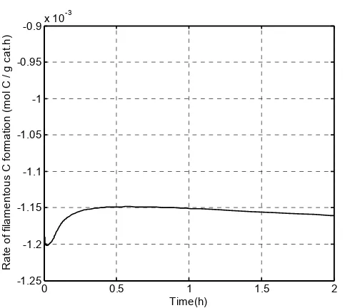
Figure 6 depicts the rate of filamentous carbon formation in which the negative values indicate that filamentous carbon is not formed in our model. Many reviews have been done regarding the formation on filamentous carbon. It has been proposed that catalyst deactivation by carbon deposition depends on the amount, type and location of carbon formed. Quincoces et al. [5] suggested that catalyst promoted with 3% of Ca presents lesser amount of whisker (filamentous) carbon with respect to Ni/Al2O3 catalyst. The CaO
addition inhibits the whisker carbon formation and is therefore more stable. This stability is related to the formation of more reactive carbonaceous residues that act as reaction intermediate during methane reforming. According to Kim et al. (2000) [14], the minimum metal particle diameter needed to form filamentous carbon is 6 nm. The Ni particle size used in the simulation is 112 nm. Theoretically, filamentous carbon should be formed in this model based on this criterion. However, this phenomenon did not happen, and can be attributed to the inappropriate equations used in the model.
1
From the simulation results, the rate of encapsulating carbon formation and the site coverage of encapsulating carbon is relatively low. The catalyst used in this model also presented a high activity which attributed to the effect of Al2O3
which serves as a good support for Ni. The simulation results also showed that filamentous carbon is not formed in this model. Although the addition of CaO promoter has been proven to inhibit the filamentous carbon formation, the factor of Ni particle size has shown that there should be a significant amount of filamentous carbon formed. This could be due to the
inappropriate equations used to calculate the rate of filamentous carbon formation. However, this research serves as a good starting point for the subsequent studies in micro+kinetic modeling.
aNi + Ni surface area in catalyst (m2/g cat)
A + Stoichiometric matrix
CNi,f + Carbon concentration below the Ni
surface (mol C/m3 Ni)
CNi,r + Carbon concentration on the support side
(mol C/m3 Ni)
!! !"$
&
'
"
!
"
#
"
#
$
"
- 5. Weight of encapsulating carbon
& &
!
#
!
#
$
"
Cp + Weight of encapsulating carbon (g C/g
Dc + Effective diffusivity for carbon in Ni
(cm2/s)
E + Activation energy for reaction (kJ/mol) fNi + Weight fraction of Ni in catalyst (g Ni/g
cat)
k + Preexponential factor in Arrhenius equation (mol/site.s)
kp + Turnover frequency for encapsulating
carbon (mol C/site.s)
m + Number of elementary reaction steps MC + Molecular weight of carbon (g C/ mol C)
MNi + Molecular weight of Ni (g Ni/mol Ni)
Pi + Partial pressure of species (bar)
rcp + Rate of encapsulating carbon formation
(mol C/g cat.h)
r + Rate of filamentous carbon formation (mol C/g cat.h)
segregation layer (g C/g Ni)
θi + Fraction of sites covered by surface
species
* + Active sites on catalyst
b + Stoichiometric number of reaction OGseg + Gibbs energy for segregation layer of Ni
(cal/mol)
OH°298 + Standard enthalpy+change of reaction
(J mol+1) Suppression of Carbonaceous Depositions on Nickel Catalyst for the Carbon Dioxide
Reforming of Methane. 3 30
6 . 177: 15+23.
[3] Wang, S. and Lu, G.Q.M. (1996). Carbon Dioxide Reforming of Methane to Produce Synthesis Gas Over Metal+Supported Catalysts: State of the
Art. )" . 10: 896+904.
[4] Ferreira+Aparicio, P., Guerrero+Ruiz, A. and Rodriguez+Ramos, I. (1998). Comparative Study at Low and Medium Reaction Temperatures of Syngas Production by Methane Reforming with Carbon Dioxide over Silica and Alumina
Supported Catalysts. 3 30
6 . 170: 177+187. evolution during catalyst deactivation and
comparison with experiment.
. 65: 5550+5558.
[7] Chen, D., Lødeng, R., Anundskas, A., Olsvik, O., and Holmen, A. (2001). Deactivation during Carbon Dioxide Reforming of Methane over Ni Catalyst: Microkinetic Analysis.
. 56: 1371+1379.
[8] Chen, D. (2002). " .
[9] Aparicio, L. M. (1997). Transient Isotopic Studies and Microkinetic Modeling of Methane Reforming
over Nickel Catalysts. " . 165: Support Phase and Preparation Technique.
3 40 . 16: 269+277.
[12] Ding, R. G., and Yan, Z. F. (2001). Structure Characterization of the Co and Ni Catalysts for Carbon Dioxide Reforming of Methane.
# . 68: 135+143.
alumina Aerogel Catalysts. 3 30
6 . 197: 191+200 .