REQUEST ANALYSIS
OF DGPS/IMU ON THE AIR-BORNE INSAR SYSTEM
Liansheng LOU a, *, Ju Zhang a, Hao Zhenga, Zhiming LIU a a
Xi’an research institute of surveying and mapping,Shannxi,Xi’an,[email protected]
Commission VI, WG VI/4
KEY WORDS: airborne, SAR, IMU/DGPS, attitude compensation, motivation compensation, DEM generation
ABSTRACT:
The DGPS/IMU can measure position and velocity extremely high, and it is widely used in air-borne InSAR system. The passage based on the DGPS/IMU’s action in the airborne InSAR system, makes sure the interference phase accuracy, from the analysis of the interference phase accuracy influence by InSAR imaging motivation compensation makes sure the interference phase accuracy, and analyzes the system’s request of DGPS/IMU from the DEM accuracy’s influence by DGPS/IMU’s surveying error. At last the
paper advances the accuracy request of the DGPS/IMU system, and provides basis for the InSAR system’s selection of DGPS/IMU system.
* propriate person in cases with more than one author.
1. PREFACE
According to the GPS/IMU’s working principle, GPS/IMU can accurately measure the platform’s position, velocity and attitude parameters. In a few or no ground control point situation, the airborne InSAR system must use GPS/IMU system to measure the radar antenna’s position, velocity and attitude, in order to serve the InSAR data processing. Combined with radar working, SAR imaging and InSAR basic principle, the GPS/IMU’s main usage in the airborne InSAR system contains three factors. Using GPS/IMU to do the attitude transformation compensation. According to the InSAR imaging requirement, the attitude of the platform which fixed the radar antenna must maintain smooth. However, influenced by the air current or other factors, the plane’s attitude transforms deeply, so it is necessary to do the attitude compensation. In the process, it needs the changing value measured by the GPS/IMU, after the computer processing, then through the signal instruction to control the platform’s waiting and to serve electric machine to do the compensation. The main requirement of the DGPS/IMU is that satisfying SAR imaging with no defocusing and the attitude transformation influence can be compensated by the system antenna’s design, so the requirement is not high, and this passage will not make deeply analyzing. Using DGPS/IMU data to do InSAR imaging motion compensation. By two interference complex image’s phase difference, the InSAR system can do elevation surveying, so the phase accuracy is the main factor which influence the system’s elevation measurement accuracy. Because the motion compensation of InSAR system imaging heavily influences the system’s phase accuracy, in order to ensure the system phase accuracy, it advanced higher requirement to InSAR imaging motion compensation. Otherwise to the airborne InSAR system, the primary, secondary radar antennas are fixed on the same stable platform, their motion parameters are same too. And this situation certainly will make the primary, secondary complex images’ interference declining, and bring out some interference phase error [1] [2]. In order to maintain the imaging phase accuracy better, it needs high accuracy DGPS/IMU data to do the InSAR
imaging motion compensation. Using DGPS/IMU data to do the InSAR measurement altitude. Based on InSAR measurement principle, it is needed to be fixed high accuracy DGPS/IMU system in the InSAR system to measure the radar antenna’s position and baseline inclination angle, and then work out the ground target point’s altitude. Meanwhile, if there are no ground control points, in the ground target horizontal coordinates’ working out, not only needs the radar antenna’s position but also needs to use high accurate DGPS/IMU system to measure the plane’s flying velocity. In order to satisfy a certain accurate requirement, the InSAR system must make use of DGPS/IMU. Therefore the passage do the research on InSAR imaging motion compensation and the requirements of DGPS/IMU’s in the InSAR measurement altitude system.
2. REQUIREMENTS OF DGPS/IMU IN THE
AIRBORNE INSAR SYSTEM
(1)Requirements of DGPS/IMU in InSAR imaging motion compensation
·
·
Real air lineA
Ideal air line
Pn Xn,Y
n,Z
n Y
Z X
O
H
R B
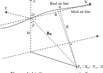
Figure 1 Air line error geometric figure
As in Figure 1, InSAR imaging motion compensation is that compensate the airplane’s real flying track point A to ideal flying track point B. Supposing
[
XA( ) ( ) ( )
tm ,YA tm ,ZA tm]
is theairplane’s real flying track point A’s coordinate at tm;
( ) ( ) ( )
[
XB tm ,YB tm ,ZB tm]
is the airplane’s ideal flying track pointCorresponding author. This is useful to know for communication with the apItem stem from: National Natural Science Foundation of China 40871205
International Archives of the Photogrammetry, Remote Sensing and Spatial Information Sciences, Volume XXXIX-B1, 2012 XXII ISPRS Congress, 25 August – 01 September 2012, Melbourne, Australia
]
B’s coordinate at tm. Meanwhile the coordinate of the airplane which flying even in straight line along the ideal flying track is , V is the airplane’s velocity, is slow time, the transmitting pulse time, T is transmitting pulse repeat cycle, m is transmitting pulse serial number.
[
Vtm,0,0If it is imaged of the ground target point Pn, which coordinate is , is the distance between radar antenna and target point when m=0. The requirement of DGPS/IMU in InSAR imaging motion compensation is that it can analyze the correction quantity ΔR’s influence by the velocity and radar antenna’s position coordinates measured by DGPS/IMU, which can be represented as[3-6]:
( )
θ ,RBcos( )
θ ] RB coordinate to represent of A’s coordinate, meanwhile using RB replace , finally putting them in the up equation, it can get:Distance correction error is in the echo field, so in the imaging it arises the phase error (unit: degree) is:
π
Put equation(2) into equation(3):
( )
( ) ( )
( )
By the InSAR altitude measurement principle, phase error to InSAR altitude measurement accuracy’s influence can be represented in follow equation [7]:
(
)
Thereinto B is the baseline length,
β
is the baseline inclination angle.Put equation (4) into equation (5) , it can get:
( )
By the system’s designing and imaging requirement, by equation (6) it can ensure the velocity and position measurement requirement of DGPS/IMU in InSAR imaging motion compensation.
(2)Requirements of DGPS/IMU in InSAR altitude measurement
The InSAR working principle geometry relationship can be seen in figure 2. In figure 2, XYZ is Gauss coordinate system and V axis is the airplane’s flying direction, which is perpendicular to the imaging side ROZ.
r1
Figure 2 InSAR imaging geometry relationship By the interference principle and triangle geometry relationship, the ground points’ altitude h can be represented in equation (7) [8-11]
Thereinto: (2)
distance between radar antenna A1、A2 and the ground points; R1、R2 is the distance between radar antenna A1、A2 and ground points.
(4)
In the aspect of horizontal coordinates working out, by the InSAR imaging principle, azimuth imaging is implemented by Doppler frequency match filtering, when imaging, it should estimate the Doppler frequency. Suppose the airplane’s flying velocity vector is Vv, the vector from point A1 to ground point P
is Pv. Finally through out the Doppler estimation it should accurately acquire Vv and Pv imaging plane’s converging angle [3][5]
, and this is SAR imaging’s intrinsic character, by this it can get:
Thereinto:
⎟
In equation (9),(10), D is ground distance in the imaging plane of ground point P, and D=R1sin(θ); VX,VY,VZ is the airplane’s flying velocity vector; Ψ is the converging angle between the airplane’s flying direction and the Y axis; Xs,Ys is radar antenna A1’s X,Y coordinates; fd is the center Doppler frequency.
International Archives of the Photogrammetry, Remote Sensing and Spatial Information Sciences, Volume XXXIX-B1, 2012 XXII ISPRS Congress, 25 August – 01 September 2012, Melbourne, Australia
Differentiated equation (7), (9) , it can get:
Baseline inclination angle unit:s
Accur
By the requirements of the system’s performance and designing, according to equation (11), (12) it can ensure the measurement requirements of DGPS/IMU’s velocity and position in DEM generation. From equation (11), (12), it can be known that the DGPS/IMU’s measurement error is just DEM’s influence error.
3. SIMULATION ANALYSIS
Supposing the airplane’s flight altitude H is 7000m; the radar working band X(which wavelength is 0.032m); the radar center side-looking angle θ is 50°; the baseline declination angle
β
is 45°; the baseline length is 1.5m; the converging angle Ψ between the airplane flight direction and Y axis is 20°; the airplane’s flight velocity is 140m/s. Usually the airplane must fly horizontally when the radar is working, so VZ will be 0; the image resolution is 0.5m, so by sampling theorem the pulse repeating frequency(PRF) will be 280Hz; the GPS orientation three-axis’s accuracy maintain consistently. As a result of that the maximum impact position of velocity compensation’s on phase accuracy is at2
Figure 4 Baseline inclination angle’s error’s influence to altitude accuracy
0 5 10 15 20 25 30
Baseline inclination angle unit:s
Accu
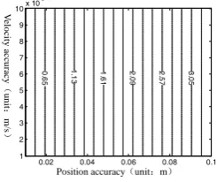
Figure 5 Baseline inclination angle’s error’s influence to horizon accuracy According to equation (6), figure 3 is an isoline map which
describes DGPS/IMU’s position and measure accuracy arises altitude accuracy affluence by InSAR imaging motion compensation that results phase, and the unit is meter.
0.000 0.002 0.004 0.006 0.008 0.010 0.00
Velocity error unit:m/s According to equation (6), figure 4 describes the situation about
DGPS/IMU’s measure baseline inclination angle error affluences altitude accuracy. Meanwhile, figure 5 describes the situation about DGPS/IMU’s measure baseline inclination angle error that affluences horizon accuracy by equation (12), figure 5 describes the situation about DGPS/IMU’s measure velocity error that affluences horizon accuracy by equation (12).
0
elocity a
cc
Position accuracy unit:m
Figure 6 Velocity error’s influence to horizon accuracy
4. CONCLUSION
We can get follow conclusions from the passage’s analysis: (1) At present, the DGPS/IMU’s velocity measure accuracy is rather high, such as POS/AV 510’s later-processing accuracy is 0.005m/s. From figure 3, we can know that the velocity measure error has no influence to motion compensation. Figure 3 DGPS/ IMU accuracy’s influence to altitude accuracy
International Archives of the Photogrammetry, Remote Sensing and Spatial Information Sciences, Volume XXXIX-B1, 2012 XXII ISPRS Congress, 25 August – 01 September 2012, Melbourne, Australia
(2)From figure 3, if motion compensation wants to satisfy the requirement of 1:1 ten thousand topographic map which altitude’s accuracy is (±2meter), the DGPS/IMU’s position accuracy should better than ±0.06m.
(3)From figure 4,5,6 we can know that, to an airborne InSAR system, POS/AV(later- processing position accuracy is about ±0.05~±0.3m, the velocity there quantum are ±0.005m/s, the angle velocity’s measure accuracy is ±0.005° ) completely satisfies the requirement that with no control points’ 1:10000 topographic map DEM generation accuracy (mountain region’s horizon accuracy is ±5 m).
5. REFERENCES
[1]Franz Leberl,Radargrammetry for Image Interpretation[J], ITC Technical Report , 1978
[2]H.A.Zebker,C.L.Werner,P.A.Rosen,and S.Hensley. Accuracy of topographic maps derived from ERS-1 interometric radar[J], 1994. IEEE Trans. Geosci. Remote Sens.,32(4):823-836.
[3]Bao zhen, Xing mengdao, Wang tong. Radar imaging technique[M].Beijing: Electric industry press,2005.
保 ,邢孟道,王彤. 雷达成像技术[M]. 北京:电子工业
出版社,2005.
[4]Yuan xiaokang. Introduce to the Spaceborne Synthetic Aperture Radar[M].Beijing: Defense industry press, 2003
袁孝康. 星载合成孔径雷达导论[M]. 北京: 防工业出版
社, 2003.
[5]CUMMING LAN G,WONG FRANK H. Spaceborne Synthetic Aperture Radar Algorithm and Implemention[M].Hong wen and etc, translation. Beijing: Electric industry press, 2007: 132-133.
CUMMING LAN G,WONG FRANK H合成孔径雷达算 法与实现[M]. 洪文,等译. 北京:电子工业出版社, 2007: 132-133.
[6]Lou liangsheng, Tang xiaotao, Liu zhiming. DGPS/IMU data’s application in airborne InSAR imaging motion compensation [J]. Surveying and mapping Science and technology Journal,2010,27(6):420-423.
楼良盛,汤晓涛,刘志 . DGPS/IMU数据在机载InSAR 成 像 运 动 补 偿 中 的 应 用[J] . 测 绘 科 学 技 术 学 报 ,2010, 27(6):420-423.
[7]Lou liangsheng, Li siwei, Liu zhiming. Airborne InSAR system’s DEM generation technique based on DGPS/IMU[J]. Surveying and mapping Science and technology Journal, 2009, 26 (5):344-346.
楼 良 盛 , 刘 思 伟 , 刘 志 . 基 于 DGPS/IMU 的 机 载 InSAR系统DEM生成技术[J] . 测绘科学技术学报,2009, 26(5):344-346.
[8]Z. Rodriguez, J.M. Martin. Theory and Design of Interometric Synthetic Aperture Radars [J] . IEE, Proceedsings-F, Vol, 193, No. 2, April 1992: 174-159 [9]Cai guolin, Liu guoxiang, Li yongshu. A InSAR interference
map filtering algorithm based on wavelet analysis[J]. Surveying and mapping Journal, 2008,37 3 : 293-300
蔡 林,刘 祥,李永树. 一种基于小波分析的 InSAR
干涉 滤波算法[J]. 测绘学报,2008,37 3 : 293-300 [10]Yu jintao, Chen ying. A new InSAR interference strip map
filtering method[J]. Surveying and mapping Journal, 2004,33(2):121-126
于晶涛,陈鹰. 一种新的 InSAR 干涉条纹 滤波方法[J].
测绘学报,2004,33 2 : 121-126
[11]H.A.Zebker,C.L.Werner,P.A.Rosen,and S.Hensley. Accuracy of topographic maps derived from ERS-1 interometric radar[J], 1994. IEEE Trans. Geosci. Remote Sens.,32(4):823-836
Revised January 2011
International Archives of the Photogrammetry, Remote Sensing and Spatial Information Sciences, Volume XXXIX-B1, 2012 XXII ISPRS Congress, 25 August – 01 September 2012, Melbourne, Australia