OBJECT-SPACE MULTI-IMAGE MATCHING OF MOBILE-MAPPING-SYSTEM
IMAGE SEQUENCES
Yung-Chuan Chen a,*, Yi-Hsing Tseng b, Chia-Yu Hsieh b, Ping-Chuan Wang b, Po-Ching Tsai b
aDept. of Construction Science and Engineering, De-Lin Institute of Technology, #1 Ln. 380, Qingyun Rd., Tucheng
Dist., New Taipei City, Taiwan - [email protected]
b Dept. of Geomatics, National Cheng Kung University, #1 University Road, Tainan, Taiwan - [email protected],
(p66971018, peterson9623, fred1988715)@gmail.com
Commission V, ICWG V/I
KEY WORDS: Photogrammetry, Terrestrial, Mobile, Image, Sequences, Matching, Mapping.
ABSTRACT:
This paper proposes an object-space multi-image matching procedure of terrestrial MMS (Mobile Mapping System) image sequences to determine the coordinates of an object point automatically and reliably. This image matching procedure can be applied to find conjugate points of MMS image sequences efficiently. Conventional area-based image matching methods are not reliable to deliver accurate matching results for this application due to image scale variations, viewing angle variations, and object occlusions. In order to deal with these three matching problems, an object space multi-image matching is proposed. A modified NCC (Normalized Cross Correlation) coefficient is proposed to measure the similarity of image patches. A modified multi-window matching procedure will also be introduced to solve the problem of object occlusion. A coarse-to-fine procedure with a combination of object-space multi-image matching and multi-window matching is adopted. The proposed procedure has been implemented for the purpose of matching terrestrial MMS image sequences. The ratio of correct matches of this experiment was about 80%. By providing an approximate conjugate point in an overlapping image manually, most of the incorrect matches could be fixed properly and the ratio of correct matches was improved up to 98%.
* Corresponding author.
1. INTRODUCTION
A terrestrial Mobile Mapping System (MMS) is capable of capturing image sequences along the vehicle trajectory for the collection of geo-spatial information. Through the data processing of the integrated Positioning and Orientation System (POS), the exterior orientation of each image can be retrieved. Coordinates of an interested point, therefore, can be determined by space intersection of overlapping images. Identification of conjugate image points in image sequences is required for this application. Manual measurement is a reliable way to obtain conjugate points, but it is certainly inefficient.
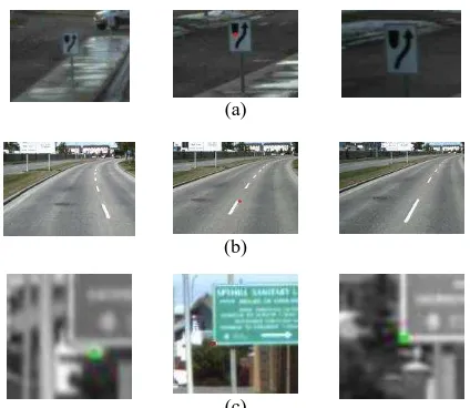
Conjugate points can be determined automatically and efficiently by using either image-space or object-space image matching methods. Traditional area-based image matching methods are commonly-used image-space matching methods, but they are not reliable to find conjugate points due to image scale, viewing angle variations, and object occlusions. Fig. 1 illustrates these difficulties of MMS image matching. The red points of middle images in Fig. 1 are target points, and it is expected that conjugate points of neighboring images can be found by image matching. Fig. 1(a) shows road signs of different scales due to the varying positions of exposure. Fig. 1(b) shows road centerlines of different view angles which will cause matching failure of the terrestrial multi-camera MMS images. The middle image of Fig. 1(b) shows a target point on a road centerline, but it is difficult to find its conjugate points of neighboring images by area-based image matching. Fig. 1(c) illustrates object occlusions. The middle image of Fig. 1(c) shows a target point on a road sign, and its conjugate point can
be found correctly in the right image (green point). But in the left image of Fig. 1(c), the image-space matching result (green point) is incorrect due to the background occlusion.
(a)
(b)
(c)
Figure 1. Difficulties of MMS image matching: (a) Image scale variations, (b) Image viewing angle variations, (c) Object
occlusions.
In this paper, the object-space multi-image matching procedure is proposed to deal with these problems of image scale variations, viewing angle variations, and object occlusions. International Archives of the Photogrammetry, Remote Sensing and Spatial Information Sciences, Volume XXXIX-B5, 2012
2. OBJECT-SPACE MULTI-IMAGE MATCHING
In this section, an object space multi-image matching procedure will be proposed to deal with the problems of image scale variations and viewing angle variations. Different from matching original image patches applied by traditional area-based image matching algorithms, this algorithm suggests a pseudo patch in object space and matches the images back-projected from the original images onto this patch. A series of pseudo patches may be assumed along the 3D vector from the perspective center of an image to a selected target point, and the best matching can be found among the assumed patches.
2.1 Back-projection
In theory, if the overlapping images are projected back to the object-space without occlusion, the projected patches will form identical projected images which can reduce the scale variations and the viewing angle variations. The principle of back-projection from MMS image sequences is depicted in Fig. 2. Some major procedures of back-projection are as follows.
(1) The interior and exterior orientation parameters of the MMS image sequences are retrieved from POS.
(2) The true object surface is unknown, so that a pseudo patch is used. The orientations of these pseudo patches should be similarly orientated to be parallel to the real surfaces, so that the problems of scale variations and viewing angle variations can be solved. For example, if the target point is on a road sign, the pseudo patches should be vertical planes. The mesh in Fig. 2 is one of these vertical pseudo planes.
(3) The (X,Y,Z) coordinates of each grid in the mesh are mapped onto images by means of the collinearity equation, and the gray value of the grid is determined by the gray levels of the pixel coordinates.
(4) The green mesh in Fig. 2 is a back-projected image from image 1. For other patches, the same processes are preformed.
(5) When all of the original images are back-projected onto the mesh, the image matching will be performed on these back-projected images.
Figure 2. The implementation of back-projection from MMS image sequences.
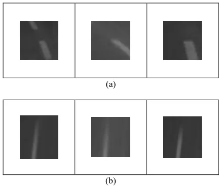
Focused on the determination of points on building walls, road signs and road surfaces, this paper preliminarily proposes two types of pseudo patches, which are vertical pseudo planes and horizontal pseudo planes. For most of the road sign images, the results of back projection to a vertical pseudo plane can reduce the scale variations. Fig. 3(a) shows an example of 3 original images of a road sign, and Fig. 3(b) shows the results of back projection from a vertical pseudo plane. The results indicate that the scale variations are reduced by back-projection.
(a)
(b)
Figure 3. An example of road sign image back projection: (a) the original images and (b) back-projected images of vertical pseudo patch, in which the scale differences between images are
reduced.
For most of the road surface images, the results of back projection to a horizontal pseudo plane can reduce the viewing angle variations. Fig. 4(a) shows an example of 3 original images of a road surface, and Fig. 4(b) shows the results of back projection from a horizontal pseudo plane. The results indicate that the viewing angle variations are reduced by back-projection.
(a)
(b)
Figure 4. An example of road surface image back projection: (a) the original images and (b) back-projected images of horizontal pseudo patch, in which the viewing angle differences between
images are reduced.
To perform the matching in object space, a series of pseudo patches need to be assumed in a pre-set searching range. For each possible location of pseudo patch, all overlapping original images are back-projected onto the pseudo patch, and then image matching is performed with the back-projected images.
2.2 Object Space Matching
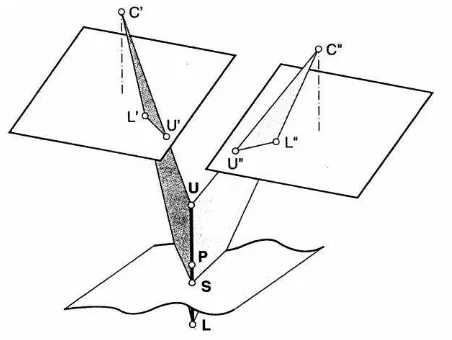
For airborne images, an object-space matching method is commonly used to search the conjugate image patches along a vertical line, which is called Vertical Line Locus (VLL) (Gyer, 1981; Bethel, 1986). The principle of VLL is depicted in Fig. 5, in which C’ and C” are perspective centers. For a point in object space whose X and Y coordinates are known, a vertical line is made to pass through the point. Let S be the true (but unknown) elevation of the point and let P be the approximate elevation. The pre-set searching range determines the lower (L) and upper (U) bounds of P. The height is divided vertically by constant intervals between L and U along the vertical line. A rectangular patch of each discrete height is projected back onto both images. The matching begins at the lower bound. The
template and the matching windows are centered at L’ and L”.
A similarity measurement is performed for evaluation. The matching procedure repeats for each discrete height within L and U. The correlation coefficient of S must be the maximum of similarity measurements. The VLL method is useful for the automatic generation of DEMs (Schenk, 1999; Krupnik and Schenk, 1994).
Figure 5. The principle of vertical line locus (Schenk, 1999). Searching along VLL is not suitable for terrestrial MMS image matching, because terrestrial MMS images are captured horizontally. This paper proposes a modified searching method based on VLL for terrestrial MMS image matching in object space. The major differences between VLL and modified object image matching are as follows (Chen, 2011).
(1) Most of the VLL systems use only two images for matching. Theoretically, using more than two images would improve accuracy and reliability. Object space matching is very useful for matching more than two images. So that in this paper, the matching of MMS image sequences is performed with multiple overlapping images.
(2) The rectangular patch of VLL is taken from the DEM or DSM. The patch for matching of terrestrial MMS image sequences is assumed to be a plane.
(3) The pseudo patch of VLL is shifted vertically. The search direction of terrestrial MMS image sequences is not vertical but is from perspective center to the interested point.
Fig.6 shows the principle of object-space multi-image matching of MMS image sequences. Let the blue point C represent the perspective center and let the red point A in image 1 be a selected target point. The searching direction of MMS image sequences is from perspective center (point C) to the selected target point A. P1 to Pn denote a series of pseudo patches along the searching direction. The initial searching range along the searching direction from the primary image is set to 200m. The pseudo patch is shifted within constant intervals of 5m along the searching direction. A modified NCC (Normalized Cross Correlation) coefficient of each pseudo patch can be calculated to evaluate the matching similarity. The maximum value indicates that the corresponding patch is the object-space position of the target point.
A coarse-to-fine procedure of object-space multi-image matching is adopted. The previous best matching position is used as the new approximate position which is the center of searching range. The searching range is further set to 10m and the pseudo patch is shifted within constant intervals of 1m along the searching direction. At the next iteration, the same processes are preformed over again. If accuracy is considered more important than speed, the searching range can be further set to 40cm and the shift interval is set to 1cm.
Figure 6. The principle of object-space multi-image matching of MMS image sequences.
2.3 Similarity Measurement in Object-space Matching
Several formulas of matching index were tried in this research, including average NCC (Normalized Cross-Correlation), YARD (Yet Another Reconstruction Dataprogram) (Wiman, 1998), and a modified YARD. YARD is a system for the automatic generation of DSMs through matching in object space. In
Wiman’s (1998) study, there is no primary image while we do have in our research. Thus the YARD is modified for our application. The modified YARD outperformed the other two. It is therefore adopted in our program. Eq.(1) shows the formula of the modified YARD.
g
k is the projected imagesl window of modified YARD is the average of projected images from multiple overlapping images.
Once the interested point is chosen, a series of pseudo patches are created. Each patch can generate several projected images and these projected images are used for matching.
Each pseudo patch will determine a correlation coefficient which evaluates the matching similarity. The maximum value indicates that the corresponding pseudo patch is the best fitting to the real object surface.
2.4 Modified Multi-window Matching
In order to solve the problem of object occlusion in Fig. 1(c), a multi-window matching test is proposed. In addition to the conventional center window, 8 matching windows shown in Fig. 7 are also used to find the best matching. Fig. 7 shows an example of the best matches of the 9 windows. Among them, window 1, 4 and 7 have the higher matching indices and their results will be used.
With 9 sub-images, each pseudo patch will retrieve 9 correlation coefficients. Fig. 8 shows the difference between window 1 and wind 3. Because of the influence of background, the matching index of window 1 will be higher than window 3 in this case.
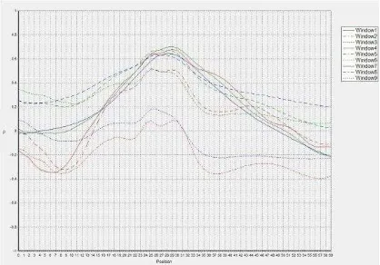
Different correlation coefficients of the 9 windows are shown in Fig. 9. Worse results of different windows are filtered and the best matching position are determined by the highest correlation coefficient.
Figure 7. The 9 windows used for the proposed multi-window matching test.
(a) Window 1
(b) Window 3
Figure 8. The influence of background with window 1 is less than window 3.
Figure 9. Different correlation coefficients of the 9 windows.
The size of matching window in our study is 5151 pixels. Two different windows sizes are compared, and 5151 pixels’ result is better than 101101 pixels’. More incorrect conjugate images involved when the size of matching window is
101 101 pixels.
2.5 Determination of Object Point Coordinate
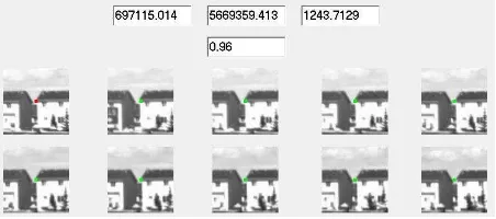
The coordinates of object point are determined by a combination of object space multi-image matching and modified multi-window matching. Fig. 10 shows a red point in the left-uper image which is the target point. The conjugate points should be found on the oher images. Each modified YARD coefficient of pseudo patches can be calculated. The position of the target point in object space is determined by the best matching index. Fig. 10 shows the result of matching which indicates the coordinates, correlation coefficient and the conjugate points with green points on MMS image sequences.
Figure 10. Result of object-space matching (The coordinates of the determinate point and the correlation coefficient).
The proposed method performs searching and matching conjugate images automatically. When an operator selects a target point in a viewing image on screen, it takes care of image matching and delivers the object coordinates. Although it works reliable in most cases, incorrect matching results are inevitable. Under these circumstances, the operator is asked to provide an approximate conjugate image point in any overlapping image. This new information will greatly help for the algorithm to reduce the possible searching space, and most incorrect matching results can be fixed.
3. EXPERIMENTAL RESULTS
The program of multi-image matching in object-space was developed with C++ language. When an operator selects a target point in a viewing image on screen, the software performs matching of conjugate images automatically and the ground coordinates of the target point are shown in the system.
3.1 Test Data Description
The proposed method has been applied to different types of point features. A set of VISAT test data provided by Department of Geomatics Engineering, University of Calgary, was used for the experiments. A variety of point features were selected for test, which were categorized into 5 types including clear features, clear features with simple background, clear features with complicated background, vague features, and road features (Fig. 11). For each feature type, 10 point features were selected for test and the total number of point features was 50. Fig.12 to Fig.16 show these 50 point features.
(a).Type 1 (b).Type 2 (c).Type 3 (d).Type 4 (e).Type 5
Figure 11. Examples of 5 categories of selected point features for test: (a) clear feature, (b) clear feature with simple background, (c) clear feature with complicated background, (d)
vague feature, (e) road feature.
3.2 Results
The test results are presented from Fig.12 to Fig.16 with respect to the test data of 5 types. In those figures, showing the matching image patch with a red dot in the center means a correct matching result. The image patch bounded with a red box means an incorrect matching but it can be correctly rematched by manually giving an approximate conjugate image point. The image patch bounded with a black box means an incorrect matching and it cannot be fixed by giving an approximation.
Figure 12. Matching results of type 1 dataset.
Figure 13. Matching results of type 2 dataset.
Figure 14. Matching results of type 3 dataset. International Archives of the Photogrammetry, Remote Sensing and Spatial Information Sciences, Volume XXXIX-B5, 2012
Figure 15. Matching results of type 4 dataset.
Figure 16. Matching results of type 5 dataset.
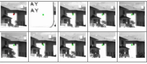
A correct matching result is shown in Fig. 10. An incorrect matching result is shown in Fig. 17. The red point is a selected target point and the other green points are conjugate points found from overlapping images automatically. This incorrect case is shown in fig. 12 with black box. The user can see the matching result on the computer’s screen to make sure whether an incorrect matching has happened.
Figure 17. Incorrect matching result is shown on computer’s screen.
Among the 50 test points, 38 points were matched successfully while 12 points failed. The correct matching ratio of this experiment was about 76%. With the 12 failed cases, the conjugate points were re-selected by manual measurements, and the point coordinates were automatically determined by multi-image matching. After the procedure, 11 feature points were matched correctly and 1 point still failed. The Matching ratio of this experiment was improved up to 98%.
4. CONCLUSIONS
This paper presents the feasibility of object-space image matching to determine the spatial positions of interested points using terrestrial MMS image sequences. The contribution of the proposed procedure will be summarized as follows: (1) Matching in object space provides a good solution to the matching problems of scale and view-angle differences. (2) Occlusion problem can be solved with the procedure of
multi-window test. (3)The modified YARD matching index can be used for similarity measurement.
Experimental results have illustrated that the developed object-space matching procedure worked reliably in most cases, but incorrect matching results were inevitable sometimes. The failures are normally caused by the complex background. Under these circumstances, the operator was asked to provide an approximate conjugate point in any overlapping image, and therefore the coordinates of the point were automatically determined by the same multi-image matching procedure. The result of experiment shows object-space multi-image matching of MMS image sequence can determine the ground position automatically and reliably.
The method proposed in this paper can match the conjugate points correctly. But for each object point, it takes a bit of time to calculate the point iteratively. Our future work will focus on improving calculation efficiency of the proposed procedure.
REFERENCES
Bethel, J., 1986. The DSR11 image correlator. In Proc. ACSM/ASPRS Ann. Convention, 4, pp.44-49.
Chen, Y.C., Tseng, Y.H., Wang, C.K., and Hsieh, C.Y., 2011. Multi-image Matching of MMS Image Sequences. In Proc. 7th International Symposium on Mobile Mapping Technology, Session I, Poland.
Gyer, M. 1981. Automated stereo photogrammetric terrain elevation extraction. Tech. Report, Gyer and Saliba, Inc. Krupnim, A. and T. Schenk, 1994. Predicting the reliability of matched points. In Proc. ACSM/ASPRS Ann. Convention, 1, pp.337-343.
Schenk, T., 1999. Digital Photogrammetry. TerraScience, Laurelville, pp. 246-247.
Wiman, H., 1998. Automatic generation of digital surface models through matching in object space. Photogrammetric Record, 16(91), pp. 83-91.
ACKNOWLEDGMENT
This research work was sponsored under the project grants: NSC 98-2211-E-224-MY2 and NSC 98-2211-E-219-MY2. The authors appreciate for the support of the National Science Council, Taiwan.