EGNOS-BASED MULTI-SENSOR ACCURATE AND RELIABLE NAVIGATION IN
SEARCH-AND-RESCUE MISSIONS WITH UAVS
P.M olinaa, I.Colominaa, T.V itoriab, P.F.Silvac, Y.Steblerd, J.Skaloudd, W.Kornuse, R.P radesf
(a)Institute of Geomatics, Universitat Polit`ecnica de Catalunya & Generalitat de Catalunya, Castelldefels, Spain -www.ideg.cat (b)Asociaci´on de la Industria Navarra, Pamplona, Spain -www.ain.es
(c)DEIMOS Engenharia, Lisbon, Portugal -www.deimos.com.pt
(d)Ecole Polyt´echnique F´ed´eral de Lausanne, Lausanne, Switzerland -www.epfl.ch´ (e)Institut Cartog`afic de Catalunya, Lausanne, Switzerland -www.icc.cat (f)Direcci´o General de Protecci´o Civil, Barcelona, Spain -www.gencat.cat
KEY WORDS:UAV, Search-and-Rescue, EGNOS, redundant IMU, Integrity Monitoring
ABSTRACT:
This paper will introduce and describe the goals, concept and overall approach of the European 7th Framework Programme’s project named CLOSE-SEARCH, which stands for ’Accurate and safe EGNOS-SoL Navigation for UAV-based low-cost SAR operations’.
The goal of CLOSE-SEARCH is to integrate in a helicopter-type unmanned aerial vehicle, a thermal imaging sensor and a multi-sensor navigation system (based on the use of a Barometric Altimeter (BA), a Magnetometer (MAGN), a Redundant Inertial Navigation System (RINS) and an EGNOS-enabled GNSS receiver) with an Autonomous Integrity Monitoring (AIM) capability, to support the search component of Search-And-Rescue operations in remote, difficult-to-access areas and/or in time critical situations. The proposed integration will result in a hardware and software prototype that will demonstrate an end-to-end functionality, that is to fly in patterns over a region of interest (possibly inaccessible) during day or night and also under adverse weather conditions and locate there disaster survivors or lost people through the detection of the body heat.
This paper will identify the technical challenges of the proposed approach, from navigating with a BA/MAGN/RINS/GNSS-EGNOS-based integrated system to the interpretation of thermal images for person identification. Moreover, the AIM approach will be described together with the proposed integrity requirements. Finally, this paper will show some results obtained in the project during the first test campaign performed on November 2010. On that day, a prototype was flown in three different missions to assess its high-level perfor-mance and to observe some fundamental mission parameters as the optimal flying height and flying speed to enable body recognition. The second test campaign is scheduled for the end of 2011.
1 INTRODUCTION
1.1 Unmanned Aircrafts in Search and Rescue missions
The use of Unmanned Aerial Vehicles (UAVs) for Search-And-Rescue (SAR) operations is not new and does often benefit from the UAV developments in other fields and not precisely for SAR operations. For example, Unmanned Aircrafts (UAs) used in the Iraq and Afghanistan wars were deployed to find people trapped in New Orleans’ buildings devastated by Hurricane Katrina’s flood waters. These UAs were equipped with thermal imaging systems to detect the body heat of storm survivors. Thinking on the gen-eral SAR context, when a small plane crashes in a remote area, or a fishing boat is lost at sea, or a hurricane devastates a region, or simply a person gets lost while he/she was hiking, SAR teams must scramble every available resource to scan vast areas for vic-tims’ evidence or wreckage. For this purpose, UAVs equipped with thermal or other sensors can be programmed to fly prede-fined search patterns at low altitudes —30 m to 150 m—, trans-mitting real-time imagery back to a ground station via a data link. Generally speaking, Wilderness Search and Rescue (WiSAR) en-tails searching over large regions in often rugged remote areas. Because of the potentially limited mobility of ground searchers, WiSAR is an ideal application where small or tactical UAVs have been used to provide aerial imagery of the search region. Al-though less spread in Europe than in North America, it can be stated that the use of UAVs —more in general, Unmanned Aerial Systems (UAS) including the Control Station (CS) and Data Link (DL)— for WiSAR is rapidly evolving (Goodrich et al., 2007).
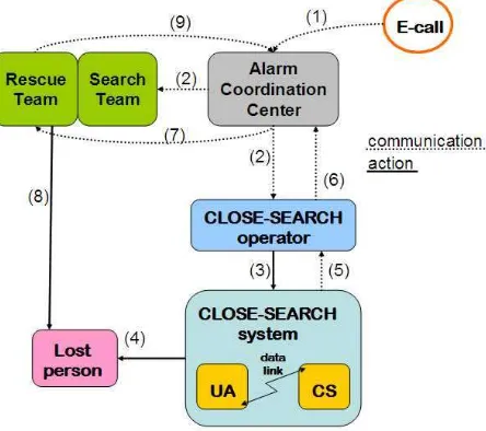
Figure 1: The CLOSE-SEARCH system within a Search-And-Rescue action chain involving a lost person
As CLOSE-SEARCH targets at search missions —notrescue
steps of the different actors in a SAR mission: (1) an emergency call is generated, (2)(3) SAR teams are activated including the CLOSE-SEARCH system, (4) the person is found, (5)(6) the po-sition of the person is forwarded back to the alarm coordination center, (7) the rescue team is activated, (8) the person is rescued, (9) a final message of mission ending is sent to the coordina-tion center. In view of the latter, one realizes that the common
alarm-operation-finding-communicationsituation is suitable for the proposed system. The output of the search system is the so-calledrescue area, a 10m x 10m region on ground in where the lost person dwells. This information is provided due to the system capacity of geo-referencing targets recognized by means of its remote-sensing component, together with and accurate and safe navigation —the description of components put in place to achieve such an objective is the aim of this paper, focusing on the
ultra-safenavigation concept.
1.2 Key application enablers and the CLOSE-SEARCH state-of-the-art contributions
As discussed, the use of UAS in SAR applications may still seem very restricted to major, seldom catastrophes, in which big efforts are deployed and the risk and consequences of loosing a platform (even causing an impact on ground) is minimized, analogously to the military applications. However, in order to spread this appli-cation closer to the public, mass-market level, where local civil protection authorities, small companies, sport clubs, etc. may benefit from it, the operation —i.e., navigation— of the UAVs shall be safe. For this to happen, three main conditions shall be met:
1. the predefined search path shall be followed within given ac-curacy and integrity levels,
2. considering the relative low flying altitude, accurate and up-to-date geospatial databases, mainly for Digital Surface Model (DSM), shall be available and integrated with the UAS, and
3. a collision avoidance system shall be in place; the so-called Sense-and-Avoid (SAA) systems.
CLOSE-SEARCH advances on the state-of-the-art for the above points 1 and 2. With respect to item 1, the aim is to achieve ultra-safe navigation as this concept is of the utmost importance when dealing with autonomous platforms, in which enhanced system robustness against undesired failures is needed. In addi-tion, nowadays the employment of UAVs is closely observed by the public as well as the state-authorities and therefore an acci-dent might be socially harmful. Although we are aware that safe navigation is just a part if the problem —safety must be ensured at several levels as for redundant communication links, duplicated mechanical components, etc.— our primary focus is the naviga-tional aspect. Thus, the use of GPS in combination with the Eu-ropean Geostationary Navigation Overlay Service (EGNOS) is considered and the relevance demonstration of the future Galileo and modernized GPS/Safety-of-Life (SoL) services is addressed.
In addition, it is objective to proof EGNOS-enabled INS and GNSS coupling schemes valid for unmanned platforms by com-bining the former concept —i.e., EGNOS-enabled INS/GNSS integrated navigation— with the use of low-cost redundant In-ertial Measurement Unit (IMU) configurations, baro-altimeters and magnetometers. Finally, the integration takes advantage of the AIM implementation, which extends the traditional Receiver Autono-mous Integrity Monitoring (RAIM) capabilities to all the navigation sensors integrated within the filter. We believe that this highly redundant configuration provides the level of precision, accuracy, and reliability needed for the navigation of a UAS/UA.
Further to this, and with respect to the item 2, CLOSE-SEARCH aims at demonstrating how 3D geospatial information —not only Digital Elevation Models (DEMs) but also and mainly DSMs— can and must be used in combination with navigation systems. The proposed concept uses 3D landscape models to improve the search operations (identifying occlusions and other limitations of aerial imagery) and avoid collision with the terrain or other ob-jects. CLOSE-SEARCH may generate useful feedback to geospa-tial data producers on the required level of detail (electrical power lines, communication towers, etc.) of their data bases.
Last but not least, we note that condition 3 shall not be interpreted as a barrier to the practical application of the proposed concept. Certainly, as mentioned earlier, the still unregulated integration of UAS/UAs into the civil regulated airspace is a major commer-cial market barrier to many applications of the UAS technology. However, the CLOSE-SEARCH application will not suffer from this as, in the circumstances of WiSAR, the use of the technol-ogy is rather sought than restricted and the proposed flying alti-tude is low. Well-coordinated SAR operations would compensate the need of carrying on-board any SAA system to avoid unpre-dictable and undesired objects in scene.
Therefore, the ultra-safe concept can be described as follows: firstly, it embodies the necessary –though not sufficient, as al-ready mentioned— condition of integrating a manifold of navi-gation sensors in a way that the precision, accuracy and reliabil-ity can be estimated. Secondly, the estimates of precision, accu-racy and reliability shall meet some [rather demanding] criteria. Thus, the proposed prototype requires the integration of EGNOS and [future] Galileo/GPS SoL services, dense and updated 3D geospatial databases, RINS/GNSS close-coupling algorithms, as well as UAS communications and remote-sensing technologies to achieve this goal. It also requires a mechanism to measure and manage the achieved reliability by this multi-sensor approach which is the so-called AIM. The reader shall find a description on the different components of the CLOSE-SEARCH system adress-ing the previously mentioned aspects.
2 THE CLOSE-SEARCH SYSTEM
2.1 Architectural overview of the system
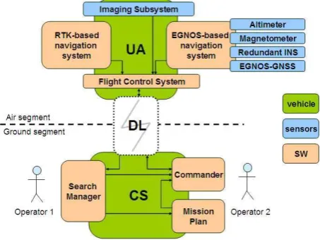
Figure 2 shows the CLOSE-SEARCH system architecture. This architecture is twofold: the air and the ground segments.
Figure 2: The CLOSE-SEARCH system architecture
Real-Time Kinematic (RTK)-based navigation system, which is the actual navigation system (back-up in CLOSE-SEARCH, left). These two subsystems provide a navigation solution to the Flight Control System (FCS), which is in charge to perform the plat-form control and interact with the communication unit on-board. Another important piece on board is the imaging subsystem, com-posed by the thermal camera, video encoders and a video recorder to eventually store images on-board. An optical camera is also envisioned to provide completeness to the remote sensing sub-system.
On the ground segment, three main pieces coexist: the Comman-der is the software component to perform the command and con-trol of the UAV (monitoring the telemetry, managing the route, etc.); the Mission Plan is based on a Geographic Information Sys-tem (GIS) platform and used to design the mission in terms of flying path, scanning patterns, image overlaps, etc.; and finally, the Search Manager is a software tool to interact with the imag-ing subsystem’s outcome, as it is very important that the user can visualize and [eventually] pin-point any object in the image. By doing this, the target is geo-referenced and the acutal position of the UA is reinserted into the Misison Plan as ahot-spoti.e. po-tential revisit area. The last two components have been entirely developed in the frame of CLOSE-SEARCH.
2.2 The imaging subsystem in CLOSE-SEARCH: optical and thermal vision
One of the fundamental objectives —not to say the most— in CLOSE-SEARCH is to find people by means of remote vision or sensing. In regard of the SAR missions requirements, two dif-ferent sensors have been chosen for the imaging subsystem. On one side, a thermal camera Raytheon 2000B is used as the main tool for remotely sensing persons. The underlying assumption is that a person is thermally contrasted against his/her background, especially in wild scenarios in which no man-made structures are present. The imaging capability independent from illumination conditions paves the way for night operations, to which the un-manned condition of the platform is also suitable. On the other side, as a complement to the thermal camera, an optical video-camera Sony 420 TVL is also considered to mitigate the potential false alarms due to miss interpretation of the thermal images and to provide sensing capability of the non-thermal targets.
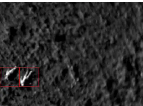
Indeed, the success of the proposed imaging subsystem is related to many factors, such as metereological conditions, image in-terpretation capability and some others. But mainly, it depends on the Ground Sampling Distance (GSD) —the finer pixels, the more chances for the operator to recognize a person. Thus, the sensor resolution and the flying height are fundamental variables to be solved towards success. In the frame of its test campaigns, the CLOSE-SEARCH system has been flown within 30 and 50 meters height over several targets to successfully validate a suit-able GSD range for person recognition, which has been estimated to lie between 5cm x 5cm and 9cm x 9cm. In addition, an As-sisted Feature Detection (AFD) mechanism has been implemented to help the user detecting potential targets on a thermal image. Figure 3 shows an example of an AFD-analyzed image taken on a real flight at 30 meters height above ground (that is, GSD of 5cm x 5cm).
As the thermal camera resolution is of 320 x 240 pixels, and that is quite low, one may think on taking advantage of the large im-age forward-overlap (acquisition frequency ranging from 4 Hz to 25 Hz) to enhance its performance. This can be achieved by the so-calledsuper resolutionwhich yields sensibly high improve-ments and can thus improve the system performance (Almeida and Tommaselli, 2003).
Figure 3: Two persons lying on the floor, sensed with a GSD of 5cm x 5cm, and the AFD mechanism providing its detection
2.3 LOS and BLOS communication: seamless operation re-gardless of topography
When dealing with UAS, continuous and reliable communication between the airborne vehicle (UAS/UA) and the ground control station (UAS/CS) is a primal feature for safe operations. There is a need of monitoring the UAS/UA permanently to ensure its correct operation and also of sending actions to it in case of mis-sion modification or abort —the so-called Command-and-Control (C2). Now, usual C2 implementations are based on radio fre-quency technologies like WiFi, which provide suitable bandwidths for C2 and payload data (telemetry, images, etc.). Radio fre-quency technology belongs to the so-called Line-Of-Sight (LOS) technologies, and that means that eventual physical obstacles be-tween the emitter and the receiver may degrade the Signal-to-Noise Ratio (SNR) and cause communication quality downgrade or even loss.
As SAR operations are likely to happen in difficult-to-access ar-eas with irregular topography, no eventual LOS set-up between the UAS/CS and UAS/UA can be assumed. Therefore, Beyond-Line-Of-Sight (BLOS) technologies (cell-based, satellite-based, etc.) play a fundamental role for mission completeness. In the frame of CLOSE-SEARCH, Worldwide Interoperability for Mi-crowave Access (WiMAX) technology has been assessed in the latest phase of the project to validate the concept of seamless LOS-&-BLOS communication between UAS/UA and UAS/CS, and will be demonstrated on the last test campaign.
2.4 GIS-based mission plan and target management
The planning and control of the mission takes place at the UAS/CS. On a first step, a GIS-based software platform is used as the mis-sion plan tool to define the actual route and actions to be executed by the UAS/UA, expressed in single waypoints. These waypoints contain orientation information (position, velocity and attitude) and action information (hovering time, flight phase, etc.) The user is then able to design the final route and provide it to the UAS/UA by means of the Controller software. With the use of LiDAR-based DSMs, achieving 0.25-2 points/m2
), not just very accurate vertical coordinates are computed for waypoints but also man-made obstacles such as buildings, powerline tow-ers and wires, etc. can be avoided. Note, though, that obstacle completeness cannot be guaranteed with current common LiDAR point densities and also due to data up-to-dateness.
the ability of selecting frames of interest (that is, featuring a tar-get) and re-feed them into the mission plan as awaypoint-to-fly. Thus, new waypoints are generated and marked as candidates to be flown again if needed. Finally, each target on the images are geo-referenced in real-time aiming to fulfill the ground accuracy geo-referecing user requirement, which is set down to 10m x 10m horizontally.
2.5 The EGNOS-based multi-sensor navigation concept
When tackling the navigational performance aspect, the key ques-tions to be answered are, firstly, how to achieve [the desired] ac-curacy and precision and, secondly, how reliable is the solution obtained. By reviewing the GNSS navigation techniques, one realizes that GPS [and GNSS] accuracy is achieved with differ-ential techniques; i.e., on the basis of measurements collected at well surveyed ground stations. The method can be more or less sophisticated, ranging from just one user established single sta-tion and simple error modelling (differential GNSS) to a multi-user regional/global network of stations and advanced error mod-elling including orbit and clock errors. EGNOS belongs to the last class. On the other side, similarly, a network of well surveyed ground stations constitutes the basis of integrity (which is the navigational reliability), as the incoming GNSS signals are con-tinuously processed and their derived measurements compared against computed reference values.
Indeed, it would be just too risky to fly predefined search pat-terns at low altitude (down to 10 meters above ground) with no differential techniques. Nonetheless, WiSAR imposes its own constraints on positioning techniques. As an example, the widely used Real-Time Kinematic (RTK) solutions are highly accurate (down to the decimeter level). On the other side, they require some time and constraints on the establishment of the surveyed reference point and supposes an eventually not-affordable com-munication link. Thus, it is not considered in the scope of the project. Clearly, a regional/global continuous differential GNSS service is the ideal solution for the proposed application, in which the teams must respond to emergency situations with a go-and-fly action, anywhere and anytime. From an integrity monitor-ing standpoint, most local differential GNSS and RTK solutions do not provide integrity figures and, therefore, are not amenable for CLOSE-SEARCH —integrity indeed deals with the avoid-ance of accidents caused by navigation signal faults, and this is of major importance as UAVs are on the eye of the storm. Section 3 is devoted to describe integrity and its particular man-agement for CLOSE-SEARCH. For the interested reader in pre-cise information about what are the EGNOS benefits and how to implement EGNOS (generally speaking, Satellite-Based Aug-mentation Systems or SBAS) on a GPS-based solution, refer-ences (CNES, 2009), (EU, 2011) and (RTCA, 1999) are pro-vided.
With respect to the integration, the navigation solution of CLOSE-SEARCH is computed in a least-squares approach, solved by Kalman filter or Normal equation, where the IMUs play the role of primary navigation sensors whose drifts are removed by EGNOS-GNSS update measurements in a close-coupling INS/EGNOS-GNSS inte-gration scheme. In other words, the mechanization differential equations are numerically integrated and the result merged by least-squares with the EGNOS-healthy (integrity functionality) and EGNOS-corrected (accuracy functionality) pseudoranges. In addition, typically redundant pseudorange measurements are used in the least-squares and monitored to perform Fault Detection and Exclusion (FDE) in standard approaches as RAIM techniques. Now, every sensor measurement (not just GNSS pseudoranges) can benefit from the least-squares potential and thus an extended
RAIM approach can be proposed due to the high redundant navi-gation sensor configuration; we call this approach the AIM func-tion. Indeed, the use of several IMUs provides a better perfor-mance not just in accuracy and precision terms but also at the fault-detection level (Waegli et al., 2009), becoming the RINS a fundamental enabler of the AIM approach. Finally, the standard system availability check, i.e. computation of confidence bounds for position and comparison against provided thresholds, is per-formed and will be extended to the full time-position-velocity-attitude domain at the latest phase of the project.
3 ON THE INTEGRITY DEVELOPMENT IN CLOSE-SEARCH
3.1 A new integrity frame for UAVs
Addressing safety on [GNSS-based] navigation leads one to deal with legal requirements describing how to proceed in navigation solution determination and what is thesafetyframe for it. Tradi-tionally, the civil aviation community has raised awareness on the need of linking the flight safety specifications, described by the International Civil Aviation Organization (ICAO), and the perfor-mance of the navigation systems (GNSS-based, mainly). The re-sults on this work was materialized on the Minimum Operational Performance Standards (MOPS) (RTCA, 1999) and, indeed, the GNSS integrity concept is the key safety enabler. Nonetheless,
safetyis an ambiguous term —that is, its meaning depends on who it interprets it, and surely the civil aviation community must understand safety in a way that hard constraints are imposed on navigation (as human lives are involved and an accident typically causes serious or even ultimate injuries). But public or cargo transportation services, like trains, buses, cars, ships, etc. are willing to benefit from integrity i.e. safety but may even not consider its application due to the too-stringent, traditional re-quirements for it based on worst-case risk definitions (Pullen et al., 2011). The goal of this section is to explain integrity and to demonstrate how it finally is suitable for navigation of non-standard platforms such, in this case, UAVs.
In order to provide a main definition, it is worth to note that in-tegrity can be understood both in terms of confidence and risk —if one is 99% confident that a system is performing correctly, there is also a 1% risk that it is performing incorrectly. A confidence-based definition of integrity is given in the ICAO GNSS Stan-dards And Recommended Practices (SARPS):”Integrity is a mea-sure of the trust which can be placed in the correctness of the in-formation supplied by the total system. Integrity includes the abil-ity of a system to provide timely and valid warnings to users.”An alternative risk-based definition is:”Integrity risk is the probabil-ity of providing a signal that is out of tolerance without warning the user in a given period of time.”Note that, as described im-plicitly in this definition, atolerancemust be taken into account when specifying the risk.
has taken the lead on providing requirements for the GNSS aug-mentation signals, and this is why the specifications of augmen-tation systems (such as EGNOS, as of interest in this paper) are often expressed in terms of cruising, taking-off and landing ap-proaches to airports. As said before, for those communities will-ing to work with different non-conventional platforms and there-fore not linked to the operational standards for civil aviation, the interpretation of the SBAS performances is not straight-forward and, actually, can be misunderstood and declared as of little usel —there is obviously a need to provide a new frame for those will-ing to use the SBAS integrity service for their platforms.
The European augmentation system, EGNOS, has been recently SoL-certified —more precisely, Approach operations with Verti-cal Guidance (APV-I) specifications are met. The actual integrity requirements for APV-I are shown in table 1
Approach HAL, VAL TTA IR
(m) (s) (- / approach)
APV-I 40, 50 10 2·10−7
Table 1: ICAO SARPs high level integrity requirements for APV-I
Back to our application, the unsuitability of such requirement manifests vigorously. Firstly, the stated ALs (40 meters on the horizontal components and 50 meters on the vertical) are not a realistic situation when dealing with a platform of an approx-imate size of 2m x 1m x 1m flying just tens of meters above ground. Secondly, the specified TTA is large enough for a wrong measurement to cause a non-negligible incident. And finally, the IR specification may seem adequate for civil aviation, but results too stringent for unmanned vehicles flying over non-populated, cordoned-off areas, which is the case in our application.
Therefore, towards the adjustment of the safety thresholds for our particular platform and application, the following is proposed:
Approach HAL, VAL TTA IR
(m) (s) (- / approach)
W2W 4, 7.5 <<10 2·10−6
GA/S 2.5, 4 <<10 2·10−6
Table 2: High level integrity requirements defined in CLOSE-SEARCH for W2W and GA/S
where:
• Waypoint-to-Waypoint (W2W) is defined as the approach covering the navigation and control actions to fly from a given waypoint to its next on the flight plan.
• Ground Approximation/Separation (GA/S) is defined as the approach covering the navigation and control actions to go from a given waypoint to the landing end-waypoint, which is the closest flying point to the ground before activating the distance-based sensor landing approach.
On one hand, HAL and VAL for the W2W phase are chosen to meet operational performance aspects, as image footprint side-overlaps (side-overlap shall be kept between 25% and 50% ac-counting for navigational errors). On the opposite, HAL and VAL for the GA/S phase respond to safety matters, as it is the most crit-ical phase. With respect to the TTA values, we identify that the
10 seconds specification for APV-I does not fit realistically our requirements —yet, we cannot quantify this figure by the time of writting this paper. The reason for long TTA is de to the use of complex satellite-based architectures for integrity. Acutally, other Airborne-Based Augmentation System (ABAS) approaches (like RAIM or the proposed AIM) suppose an improvement as the TTA would be close to the time of computation, and would not account for communication-related delays associated to the uplink/downlink to the geostationary satellites and other factors. Finally, the IR in both approaches defined in CLOSE-SEARCH are chosen to be an order of magnitude above those specificied by the ICAO All-Weather Operational Panel (AWOP) (ICAO, 1994). This increase is justified in applications with unmanned vehicles (thus involving no human lifes on board) flying over
a priorinon-populated areas (thus involving no human lifes on ground). Although the authors believe this figure may easily be increased with no loss of safety, it would require final validation by the due authorities.
3.2 EGNOS as a key enabler of navigation safety for UAVs
Once the integrity requirements are set, the next natural question is: what is the suitable navigation approach to meet those de-mands? The answer to this question is related to the computation of the so-called Protection Levels (PLs). The PLs are statisti-cal error bounds of the actual error in terms of accuracy, which is scaled by the probability of non-integrity detection (integrity risk) for compatibility reasons (see (Roturier et al., 2001)). The PLs are computed at every epoch involving both using the fol-lowing expression:
P LH,V =KH,V ·σH,V (1)
whereKH,V are the scaling factors that scale the horizontal and vertical variancesσH,V to a level compatible with the integrity requirement. Note thatσH,V depend on the satelite-to-user ge-ometry and number of satellites in view, and the precision of each satellite pseudorange depends in turn of the clock and ephemeris corrections, named User Differential Range Error (UDRE), the ionospheric corrections, named User Ionospheric Range Error (UIRE), tropospheric delays and other local errors.
As stated in the SARPs, the adequacy of SBAS integrity is posi-tive as long as the PLs are below the ALs —the total percentage of time that this is happens is defined asavailability. Thus, in view of the specifications in table 2, the following shall hold (for GA/S phase):
2.5 =ALH> P LH=KH·σH (2) 4 =ALV > P LV =KV ·σV (3) Now, we shall use the IR proposed in our application to derive the scaling K values (Roturier et al., 2001), and this yieldsKH= 6 andKV = 4.72(note thatKH = 6andKV = 5.3for APV-I operation). As in SARPs, most of the risk is allocated in the vertical component due to the better accuracy when determining the solution in the horizontal components. In conclusion,σH < 0.42andσV < 0.85must hold to achieve APV-I availability specifications (0.99 to 0.99999, as specified by ICAO) but with UAV-coherent integrity requirements.
4 PRELIMINARY RESULTS AND FUTURE WORK
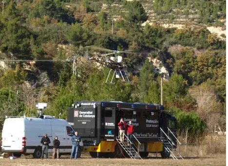
The first test campaign (November, 2010) was devoted to test the mechanical, electrical and software interfaces of the system and to demonstrate preliminary end-to-end capabilities. It is in-tended that, for the second test campaign (to be collocated in 2011), a mature CLOSE-SEARCH prototype will be presented fulfilling the user requirements and demonstrating advanced end-to-end functionalities. The first test campaign included labora-tory and pre-field tests on controlled scenarios to verify and val-idate those system components needing higher level of valida-tion within the project. The fact that previous R&D work has been brought together in the project inherently brings along dif-ferent levels of maturity for each subsystem. For example, the UAS/UA and UAS/CS provided by Asociaci´on de la Industria Navarra have been widely used in several projects and thus re-quire few test items, but other items such as the integration of the thermal camera and the EGNOS-based navigation subsystem are recently integrated components within the project. The first test campaign ended with the final field tests, carried out at the town of Copons, Catalunya (figure 4). This location was suitable for many reasons: it is an easy accessible area but far away from big urban areas, local permissions were obtained, and the area presented different land features (smooth and rough terrain, veg-etation, etc.) The second test campaign will be also carried out in the same location, but an extended area will be flown over to demonstrate realistic SAR mission potential.
Figure 4: Unmanned Aircraft and Control Station on November, 25th -the first CLOSE-SEARCH test campaign
The results were satisfactory from the overall integration point of view, and particularly for the remote sensing component. With respect to the latter, several targets were deployed on the field (ground targets, human, etc.) and the UAS/UA flew over them. The goal was to validate the proposed GSDs to enable body recog-nition using thermal images and, as described in section 2.2, this goal was achieved. Nonetheless, on the navigation/control tasks, no performance results were obtained as the equipments were used on the acquisition mode and thus no UAV control tasks were performed using the EGNOS-based navigation solution.
After the first test campaign, the project performed several simu-lations aiming to reproduce the trajectories obtained on the field test but in several GNSS constellation scenarios, that is, varying the number of GPS satellites, using or not EGNOS corrections, simulating Galileo signals, etc. This analysis is of the utmost im-portance when assessing the potential of the augmented GPS con-stellation (GPS/EGNOS), the multi-concon-stellation scenarios (GPS and Galileo) or both provided at the same time (GPS/EGNOS and
Galileo-SoL). Although the results so far are preliminary, the ob-served trend confirms that the CLOSE-SEARCH navigation sys-tem performance is much better than the GNSS-only configura-tion, which is an straight-forward result. In addiconfigura-tion, the integrity frame described in table 2 is comfortably fulfilled when using EGNOS in the proposed navigation solution. On the opposite, an EGNOS-GNSS-only solution is not enough to achieve the pro-posed level of safety, and that reveals multi-sensor configurations as necessary in UAV Navigation, Guidance and Control (NGC) systems. In addition, we believe AIM may be also demonstrated as fundamental for NGC as well.
Precisely, future work is headed towards the completion of the EGNOS-based multi-sensor navigation system and, particularly, on the implementation of the AIM component. More precisely, a main goal of the project is to demonstrate EGNOS as suitable for UAV NGC, not just due to the enhanced accuracy and preci-sion, but also to the safety i.e. integrity service. Finally, the aim of the project is proof the concept UAV+remote-sensing+multi-senor navigationsuitable for SAR missions, and thus a large area will be scanned in presence of several targets aiming at discrim-inating between human and other targets. Successful tests will proof CLOSE-SEARCH as an end-to-end search system fulfill-ing the user requirements.
ACKNOWLEDGEMENTS
The research leading to these results has received funding from the European Community7thFramework Programme (FP7/ 2007-2013), grant agreement 248137 (www.close-search-project. eu).
The project coordinators sincerely thank all partners in the CLOSE-SEARCH consortium —Asociaci´on de la Industria Navarra (Pam-plona), DEIMOS Engenharia (Lisboa), ´Ecole Polytechnique F´ed´e-ral de Lausanne (Lausanne) Institut Cartogr`afic de Catalunya (Bar-celona) Direcci´o General de Protecci´o Civil (Bar(Bar-celona)— for their work on the project and also the many colleagues at the In-stitute of Geomatics who have supported this research.
ACRONYMS
The following list contains the paper acronyms:
ABAS Airborne-Based Augmentation System AFD Assisted Feature Detection
AIM Autonomous Integrity Monitoring
AL Alert Limits
APV-I Approach operation with Vertical guidance AWOP All Weather Operational Panel
BA Barometric Altimeter
BLOS Beyond Line-Of-Sight
C2 Command-and-Control
CS Control Station
DEM Digital Elevation Model
DL Data Link
DSM Digital Surface Model
EGNOS European Geostationary Navigation Overlay Service FCS Flight Control System
FDE Fault Detection and Exclusion GA/S Ground Approach and Separation GIS Geographic Information System GNSS Global Navigation Satellite System GPS Global Positioning System GSD Ground Sampling Distance
IMO International Maritime Organization IMU Inertial Measurement Unit
IR Integrity Risk
LiDAR Light Detection And Ranging
LOS Line-Of-Sight
MAGN Magnetometer
MOPS Minimum Operation Performance Standards NGC Navigation, Guidance and Control
PLs Protection Levels
RAIM Receiver Autonomous Integrity Monitoring RINS Redundant Inertial Navigation System
RTK Real-Time Kinematic
SAA Sense-And-Avoid
SAR Search-And-Rescue
SARPs Standards And Recommended Practices SBAS Satellite-Based Augmentation System
SoL Safety-of-Life
SNR Signal-to-Noise Ratio
TTA Time-To-Alarm
UA Unmanned Aircraft
UAS Unmanned Aerial System UAV Unmanned Aerial Vehicle UDRE User Differential Range Error UIRE User Ionospheric Range Error
W2W Waypoint-to-Waypoint
WAAS Wide-Area Augmentation System
WiMAX Worldwide Interoperability for Microwave Access WiSAR Wilderness Search-And-Rescue
REFERENCES
Almeida, L. and Tommaselli, A., 2003. Enhancing image resolu-tion from image sequence. Boletim de Ciłncias Geodsicas, Vol. 9, No. 2.
CNES, 2009. Centre national d’etudes spatiales - user guide for EGNOS application developers.
EU, 2011. European union - EGNOS safety-of-life service defi-nition document (sdd), issue 1.0.
Goodrich, M., Cooper, J. L., Adams, J., Humphrey, C., Zee-man, R. and Buss, B. G., 2007. Using a mini-UAV to support wilderness search and rescue: Practices for human-robot team-ing. Safety, Security and Rescue Robotics proceedings 2007 pp. 1–6.
ICAO, 1994. International civil aviation authority(icao) all weather operational panel (awop)/15 report, 15th meeting - 12 october 1994.
Pullen, S., Walter, T. and Enge, P., 2011. Integrity for non-aviation users. GPS World, July issue 2011.
Roturier, B., Chatre, E. and Ventura-Traveset, J., 2001. The SBAS integrity concept standardised byICAO. application to EGNOS. ION GNSS 2001 proceedings.
RTCA, 1999. Minimum operational performance standards forGPS and WAAS airborne equipment.