Open Geospatial Consortium Inc.
Date: 2010-04-27
Reference number of this OGC® document: OGC 08-015r2
Version:4.0.0
Category: OGC® Abstract Specification
Editor: Roger Lott
The OGC
®Abstract Specification
Topic 2: Spatial referencing by coordinates
Copyright © 2010 Open Geospatial Consortium, Inc.
To obtain additional rights of use, visit http://www.opengeospatial.org/legal/.
Warning
This document is an OGC Standard approved by the OGC Members. The document is available for use on a Royalty Free basis.
Recipients of this document are invited to submit, with their comments, notification of any relevant patent rights of which they are aware and to provide supporting
documentation.
Document type: OGC® Publicly Available Standard Document subtype: OGC® Abstract Specification Document stage: Final
Contents
i. Preface ... iv
ii. Revision history ... iv
Foreword ... v
Introduction ... vi
1 Scope ... 1
2 Conformance requirements ... 1
3 Normative references ... 2
4 Terms and definitions ... 2
5 Conventions ... 9
5.1 Symbols ... 9
5.2 Abbreviated terms ... 9
5.3 UML notation ... 10
5.4 Attribute status ... 11
6 Spatial referencing by coordinates — Overview ... 12
6.1 Relationship between coordinates and coordinate reference system ... 12
6.2 UML model for spatial referencing by coordinates — Overview ... 15
7 Identified Object package ... 15
7.1 General ... 15
7.2 UML schema for the Identified Object package ... 17
8 Coordinate Reference System package ... 19
8.1 Reference system ... 19
8.2 Coordinate reference system ... 19
8.2.1 General ... 19
8.2.2 Principal subtypes of coordinate reference system ... 20
8.2.3 Additional subtypes of coordinate reference system ... 20
8.2.4 Compound coordinate reference system ... 20
8.3 UML schema for the Coordinate Reference System package ... 21
9 Coordinate System package ... 27
9.1 Introduction ... 27
9.2 Coordinate system ... 27
9.3 Coordinate system axis ... 28
9.4 UML schema for the Coordinate System package ... 29
10.2 Geodetic datum ... 39
10.2.1 Prime meridian ... 39
10.2.2 Ellipsoid ... 39
10.3 UML schema for the Datum package ... 39
11 Coordinate Operation package ... 47
11.1 General characteristics of coordinate operations ... 47
11.2 UML schema for the Coordinate Operation package ... 47
Annex A (normative) Abstract test suite ... 58
Annex B (informative) Context for modelling of spatial referencing by coordinates ... 61
Annex C (informative) Spatial referencing by coordinates – Geodetic concepts ... 73
Annex D (informative) Examples ... 78
Annex E (informative) Recommended best practice for interfacing to ISO 19111 ... 91
i.
Preface
This document is consistent with the second edition (2007) of ISO 19111, Geographic Information - Spatial referencing by coordinates. ISO 19111:2007 was prepared by Technical Committee ISO/TC 211, Geographic information/Geomatics, in close collaboration with the Open Geospatial Consortium (OGC). It replaces the first edition, ISO 19111:2003. The revision was based upon and replaces OGC document 03-074r4.
ii.
Revision history
Date Release Author Paragraph modified Description
7 Sept 2001 01-063 RN New document First draft for internal OGC feedback 12 Nov 2001 01-063r1
v 1.0.1
RN Various editorial comments and a
modification of the UML model
Initial feedback from CT Working Group implemented
8 Jan 2002 01-063r2 v 1.0.2
RN Various editorial comments and
modifications of the UML model
Final feedback implemented from the CT Working Group
15 Oct 2003 03-073r3 v 2.0.0
RN/AW JH/DC
Revision of UML model and accompanying text
The degree of detail of the UML model has been increased to facilitate
conversion to XML Schema. The previous model was supplemented by textual constraints. These constraints have now been expressed in the UML model. The changes to version 1.0.2 were separately described in OGC document 03-009r6. This version 2.0.0 is therefore a consolidation of that
document and version 1.0.2 of this document. Main OGC document number updated to 03-073.
2 Mar 2004 03-073r4 v.2.0.1
RN/AW DC
Editorial changes Minor editorial changes made, creating version 2.0.1 for information only of ISO TC211
8 Feb 2008 08-015 v3.0.0
RL Revision of UML model and accompanying text
Foreword
Attention is drawn to the possibility that some of the elements of this document may be the subject of patent rights. Open Geospatial Consortium Inc. shall not be held
responsible for identifying any or all such patent rights. However, to date, no such rights have been claimed or identified.
Recipients of this document are requested to submit, with their comments, notification of any relevant patent claims or other intellectual property rights of which they may be aware that might be infringed by any implementation of the specification set forth in this document, and to provide supporting documentation.
Introduction
Geographic information contains spatial references which relate the features represented in the data to positions in the real world. Spatial references fall into two categories:
those using coordinates;
those based on geographic identifiers.
Spatial referencing by geographic identifiers is defined in ISO 19112 [4]. This Abstract Specification describes the data elements, relationships and associated metadata required for spatial referencing by coordinates. It describes the elements that are necessary to fully define various types of coordinate systems and coordinate reference systems applicable to geographic information. The subset of elements required is partially dependent upon the type of coordinates. This Abstract Specification also includes optional fields to allow for the inclusion of non-essential coordinate reference system information. The elements are intended to be both machine and human readable.
The traditional separation of horizontal and vertical position has resulted in coordinate reference systems that are horizontal (2D) and vertical (1D) in nature, as opposed to truly three-dimensional. It is established practice to define a three-dimensional position by combining the horizontal coordinates of a point with a height or depth from a different coordinate reference system. In this Abstract Specification, this concept is defined as a compound coordinate reference system.
The concept of coordinates can be expanded from a strictly spatial context to include time. ISO 19108 describes temporal schema. Time can be added as a temporal coordinate reference system within a compound coordinate reference system. It is even possible to add two time-coordinates, provided the two coordinates describe different independent quantities.
EXAMPLE An example is the time/space position of a subsurface point of which the vertical coordinate is expressed as the two-way travel time of a sound signal in milliseconds, as is common in seismic imaging. A second time-coordinate indicates the time of observation, usually expressed in whole years.
In addition to describing a coordinate reference system, this Abstract Specification provides for the description of a coordinate transformation or a coordinate conversion between two different coordinate reference systems. With such information, spatial data referred to different coordinate reference systems can be related to one specified
OGC Abstract Specification — Topic 2: Spatial referencing by
coordinates
1 Scope
This Abstract Specification defines the conceptual schema for the description of spatial referencing by coordinates, optionally extended to spatio-temporal referencing. It describes the minimum data required to define one-, two- and three-dimensional spatial coordinate reference systems with an extension to merged spatial-temporal reference systems. It allows additional descriptive information to be provided. It also describes the information required to change coordinates from one coordinate reference system to another.
In this Abstract Specification, a coordinate reference system does not change with time. For coordinate reference systems defined on moving platforms such as cars, ships, aircraft and spacecraft, the transformation to an Earth-fixed coordinate reference system can include a time element.
This Abstract Specification is applicable to producers and users of geographic
information. Although it is applicable to digital geographic data, its principles can be extended to many other forms of geographic data such as maps, charts and text documents.
The schema described can be applied to the combination of horizontal position with a third non-spatial parameter which varies monotonically with height or depth. This
extension to non-spatial data is beyond the scope of this Abstract Specification but can be implemented through profiles.
2 Conformance requirements
This Abstract Specification defines two classes of conformance, Class A for conformance of coordinate reference systems and Class B for coordinate operations between two coordinate reference systems. Any coordinate reference system claiming conformance to this Abstract Specification shall satisfy the requirements given in A.1. Any coordinate operation claiming conformance to this Abstract Specification shall satisfy the
3 Normative references
The following referenced documents are indispensable for the application of this document. For dated references, only the cited edition applies. For undated references, the latest edition of the referenced document (including any amendments) applies.
ISO/TS 19103, Geographic information — Conceptual schema language
ISO 19108, Geographic information — Temporal schema
ISO 19115, Geographic information — Metadata
Normative reference to ISO 19115 is restricted as follows. In this Abstract Specification, normative reference to ISO 19115 excludes the MD_CRS class and its component classes. ISO 19115 class MD_CRS and its component classes specify descriptions of coordinate reference systems elements. These elements are modelled in this Abstract Specification.
NOTE The MD_CRS class and its component classes were deleted from ISO 19115:2003 through Technical Corrigendum 1:2006.
4 Terms and definitions
For the purposes of this document, the following terms and definitions apply.
4.1
affine coordinate system
coordinate system in Euclidean space with straight axes that are not necessarily mutually
perpendicular
4.2
Cartesian coordinate system
coordinate system which gives the position of points relative to n mutually
perpendicular axes
NOTE n is 2 or 3 for the purposes of this Abstract Specification.
4.3
compound coordinate reference system
coordinate reference system using at least two independent coordinate reference
systems
NOTE Coordinate reference systems are independent of each other if coordinate values in one cannot be
4.4
concatenated operation
coordinate operation consisting of sequential application of multiple coordinate
operations
4.5
coordinate
one of a sequence of n numbers designating the position of a point in n-dimensional space
NOTE In a coordinate reference system, the coordinate numbers are qualified by units.
4.6
coordinate conversion
coordinate operation in which both coordinate reference systems are based on the
same datum
EXAMPLE Conversion from an ellipsoidal coordinate reference system based on the WGS 84 datum to a
Cartesian coordinate reference system also based on the WGS 84 datum, or change of units such as from radians to degrees or feet to meters.
NOTE A coordinate conversion uses parameters which have specified values that are not determined empirically.
4.7
coordinate operation
change of coordinates, based on a one-to-one relationship, from one coordinate
reference system to another
NOTE Supertype of coordinate transformation and coordinate conversion.
4.8
coordinate reference system
coordinate system that is related to an object by a datum
NOTE For geodetic and vertical datums, the object will be the Earth.
4.9
coordinate set
collection of coordinate tuples related to the same coordinate reference system
4.10
coordinate system
set of mathematical rules for specifying how coordinates are to be assigned to points
4.11
coordinate transformation
coordinate operation in which the two coordinate reference systems are based on
different datums
NOTE A coordinate transformation uses parameters which are derived empirically by a set of points with known
4.12
coordinate tuple
tuple composed of a sequence of coordinates
NOTE The number of coordinates in the coordinate tuple equals the dimension of the coordinate system; the
order of coordinates in the coordinate tuple is identical to the order of the axes of the coordinate system.
4.13
cylindrical coordinate system
three-dimensional coordinate system with two distance and one angular coordinates
4.14 datum
parameter or set of parameters that define the position of the origin, the scale, and the orientation of a coordinate system
4.15 depth
distance of a point from a chosen reference surface measured downward along a line perpendicular to that surface
NOTE A depth above the reference surface will have a negative value.
4.16 easting E
distance in a coordinate system, eastwards (positive) or westwards (negative) from a north-south reference line
4.17 ellipsoid
surface formed by the rotation of an ellipse about a main axis
NOTE In this Abstract Specification, ellipsoids are always oblate, meaning that the axis of rotation is always the
minor axis.
4.18
ellipsoidal coordinate system
geodetic coordinate system
coordinate system in which position is specified by geodetic latitude, geodetic
longitude and (in the three-dimensional case) ellipsoidal height
4.19
ellipsoidal height
geodetic height
h
distance of a point from the ellipsoid measured along the perpendicular from the
4.20
engineering coordinate reference system
coordinate reference system based on an engineering datum
EXAMPLES Local engineering and architectural grids; coordinate reference system local to a ship or an orbiting spacecraft.
4.21
engineering datum
local datum
datum describing the relationship of a coordinate system to a local reference
NOTE Engineering datum excludes both geodetic and vertical datums.
EXAMPLE A system for identifying relative positions within a few kilometres of the reference point.
4.22 flattening f
ratio of the difference between the semi-major (a) and semi-minor axis (b) of an
ellipsoid to the semi-major axis; f =(a – b)/a
NOTE Sometimes inverse flattening 1/f =a/(a b) is given instead; 1/f is also known as reciprocal flattening.
4.23
geodetic coordinate reference system
coordinate reference system based on a geodetic datum
4.24
geodetic datum
datum describing the relationship of a two- or three-dimensional coordinate system to
the Earth
4.25
geodetic latitude
ellipsoidal latitude
angle from the equatorial plane to the perpendicular to the ellipsoid through a given point, northwards treated as positive
4.26
geodetic longitude
ellipsoidal longitude
4.27 geoid
equipotential surface of the Earth’s gravity field which is everywhere perpendicular to the direction of gravity and which best fits mean sea level either locally or globally
4.28
gravity-related height H
height dependent on the Earth’s gravity field
NOTE This refers to in particular orthometric height or normal height, which are both approximations of the
distance of a point above the mean sea level.
4.29 height h, H
distance of a point from a chosen reference surface measured upward along a line perpendicular to that surface
NOTE A height below the reference surface will have a negative value.
4.30
image coordinate reference system
coordinate reference system based on an image datum
4.31
image datum
engineering datum which defines the relationship of a coordinate system to an image
4.32
linear coordinate system
one-dimensional coordinate system in which a linear feature forms the axis
EXAMPLES Distances along a pipeline; depths down a deviated oil well bore.
4.33
map projection
coordinate conversion from an ellipsoidalcoordinate system to a plane
4.34
mean sea level
average level of the surface of the sea over all stages of tide and seasonal variations
NOTE Mean sea level in a local context normally means mean sea level for the region calculated from
4.35 meridian
intersection of an ellipsoid by a plane containing the shortest axis of the ellipsoid
NOTE This term is often used for the pole-to-pole arc rather than the complete closed figure.
4.36 northing N
distance in a coordinate system, northwards (positive) or southwards (negative) from an east-west reference line
4.37
polar coordinate system
two-dimensional coordinate system in which position is specified by distance and direction from the origin
NOTE For the three-dimensional case, see spherical coordinate system(4.44).
4.38
prime meridian
zero meridian
meridian from which the longitudes of other meridians are quantified
4.39
projected coordinate reference system
coordinate reference system derived from a two-dimensional geodeticcoordinate
reference system by applying a map projection
4.40
semi-major axis a
semi-diameter of the longest axis of an ellipsoid
NOTE This equates to the semi-diameter of the ellipsoid measured in its equatorial plane.
4.41
semi-minor axis b
semi-diameter of the shortest axis of an ellipsoid
NOTE The shortest axis coincides with the rotation axis of the ellipsoid and therefore contains both poles.
4.42 sequence
finite, ordered collection of related items (objects or values) that may be repeated
4.43
spatial reference
description of position in the real world
NOTE This may take the form of a label, code or coordinate tuple.
4.44
spherical coordinate system
three-dimensional coordinate system with one distance measured from the origin and two angular coordinates, commonly associated with a geodeticcoordinate reference
system
NOTE Not to be confused with an ellipsoidal coordinate system based on an ellipsoid ‘degenerated’ into a
sphere.
4.45 tuple
ordered list of values
[ISO 19136]
4.46 unit
defined quantity in which dimensioned parameters are expressed
NOTE In this Abstract Specification, the subtypes of units are length units, angular units, time units, scale units
and pixel spacing units.
4.47
vertical coordinate reference system
one-dimensional coordinate reference system based on a vertical datum
4.48
vertical coordinate system
one-dimensional coordinate system used for gravity-related height or depth
measurements
4.49
vertical datum
datum describing the relation of gravity-related heights or depths to the Earth
NOTE In most cases, the vertical datum will be related to mean sea level. Ellipsoidal heights are treated as
5 Conventions
5.1 Symbols
a semi-major axis
b semi-minor axis
E easting
f flattening
H gravity-related height
h ellipsoidal height
N northing
geodetic longitude
geodetic latitude
E, N Cartesian coordinates in a projected coordinate reference system
X, Y, Z Cartesian coordinates in a geodetic coordinate reference system
i, j, [k] Cartesian coordinates in an engineering coordinate reference system
r, polar coordinates in a 2D engineering coordinate reference system
r, , spherical coordinates in a 3D engineering or geodetic coordinate reference system
5.2 Abbreviated terms
CC change coordinates (package abbreviation in UML model)
CD coordinate datum (package abbreviation in UML model)
CCRS compound coordinate reference system
CRS coordinate reference system
CS coordinate system (also, package abbreviation in UML model)
IO identified object (package abbreviation in UML model)
pixel a contraction of “picture element”, the smallest element of a digital image to which attributes are assigned
RS reference system (package abbreviation in UML model)
SC spatial referencing by coordinates (package abbreviation in UML model)
SI le Système International d’unités
UML Unified Modeling Language
URI Uniform Resource Identifier
1D one-dimensional
2D two-dimensional
3D three-dimensional
5.3 UML notation
In this Abstract Specification, the conceptual schema for describing coordinate reference systems and coordinate operations is modelled with the Unified Modelling Language (UML). The basic data types and UML diagram notations are defined in ISO/TS 19103 and ISO/IEC 19501 [9].
In this Abstract Specification, the following stereotypes of UML classes are used:
a) <<DataType>> a descriptor of a set of values that lack identity (independent existence and the possibility of side effects); a DataType is a class with no operations whose primary purpose is to hold the
information;
b) <<Type>> a class used for specification of a domain of objects together with operations applicable to the objects;
c) <<CodeList>> a flexible enumeration that uses string values for expressing a list of potential values;
d) <<Union>> contains a list of attributes where only one of those attributes can be present at any time.
The following data types defined in ISO/TS 19103 are used:
Angle amount of rotation required to bring one line or plane into coincidence with another;
CharacterString a sequence of characters;
Date a character string which comprises year, month and day in the
format as specified by ISO 8601;
GenericName a generic name structure in the context of namespaces, defined in ISO/TS 19103;
Integer an integer number;
Length the measure of distance;
Measure result from performing the act or process of ascertaining the extent, dimensions or quantity of some entity;
Number abstract class that can be subtyped to a specific number type (real, integer, decimal, double, float);
Scale the ratio of one quantity to another;
Unit of Measure any of the systems devised to measure some physical quantity.
In addition, a Sequence type of collection is used, which contains an ordered list of values with the specified data type. The format used is “Sequence<DataType>”.
In the UML diagrams in this Abstract Specification, grey boxes indicate classes from other packages.
5.4 Attribute status
In this Abstract Specification, attributes are given an obligation status:
Obligation Definition Meaning
M mandatory This attribute shall be supplied.
C conditional This attribute shall be supplied if the condition (given in the attribute description) is true. It may be supplied if the condition is false.
O optional This attribute may be supplied.
6 Spatial referencing by coordinates — Overview
6.1 Relationship between coordinates and coordinate reference system
In this Abstract Specification, a coordinate is one of n scalar values that define the position of a single point. In other contexts, the term ordinate is used for a single value and coordinate for multiple ordinates. Such usage is not part of this Abstract
Specification.
A coordinate tuple is an ordered list of n coordinates that define the position of a single
point. In this Abstract Specification, the coordinate tuple shall be composed of one, two or three spatial coordinates. The coordinates shall be mutually independent and their number shall be equal to the dimension of the coordinate space.
EXAMPLE A coordinate tuple cannot contain two heights.
Coordinates are ambiguous until the system to which those coordinates are related has been fully defined. Without the full specification of the system, coordinates are
ambiguous at best and meaningless at worst. A coordinate reference system (CRS) defines the coordinate space such that the coordinate values are unambiguous. In this Abstract Specification, the order of the coordinates within the coordinate tuple and their unit(s) of measure shall be parts of the coordinate reference system definition.
Figure 1 — Conceptual relationship of coordinates to coordinate reference system
The semantic meaning of coordinate tuple and coordinate set is reflected in the modelling of classes DirectPosition and GM_Object respectively; this modelling is in ISO 19107 [3]. In this Abstract Specification, a coordinate reference system shall be comprised of one coordinate system and one datum (see Figure 2).
Figure 2 — Conceptual model of a coordinate reference system
NOTE A coordinate operation may be single or concatenated. Refer to Clause 11.
Figure 3 — Conceptual model for spatial referencing by coordinates
6.2 UML model for spatial referencing by coordinates — Overview
The specification for spatial referencing by coordinates is defined in this Abstract Specification in the form of a UML model with supplementary text. The UML model contains five primary UML packages, as shown in Figure 4. Each box represents a package, and contains the package name. Each arrowed line shows the dependency (at the head of the arrow) of one package upon another package.
Coordinate Operations
Coordinate Reference Systems
Coordinate Systems
Datums
Identified Objects
Figure 4 — UML model packages and dependencies
The five UML packages for spatial referencing by coordinates are more completely specified in the Clauses 7 through 11. Further context for the requirements of Clauses 7 through 11 is given in Annex B and some geodetic concepts underpinning spatial
referencing by coordinates are given in Annex C. Examples illustrating how this Abstract Specification can be applied when defining a coordinate reference system or a coordinate operation are given in Annex D. Recommendations for referencing to classes defined in this Abstract Specification are given in Annex E.
7 Identified Object package
7.1 General
One of the attributes is the object primary name. This may have alternative names or aliases.
EXAMPLE 1 A datum name might be “North American Datum of 1983” and its abbreviation “NAD83”.
Object primary names have a data type RS_Identifier which is defined in ISO 19115 whilst aliases have a data type GenericName which is defined in ISO/TS 19103.
Another attribute is identifier. This is a unique code used to reference an object in a given place.
EXAMPLE 2 A register of geodetic codes and parameters might give the NAD83 datum a unique code of “6269”.
Identifiers have a data type of RS_Identifier.
In addition to the use of an identifier as a reference to a definition in a register of geodetic codes and parameters, it may also be included in an object definition to allow reference to the object.
Object identification shall be through
a) a full object description as defined in this Abstract Specification, or
b) reference to a full object description in a register of geodetic parameters (the reference is made to the register's object identifier), or
c) both full description and reference to a description in a register. If there is a conflict between the two, the register description shall prevail.
a) and b) are alternative means of providing a full object description. b) is recommended for simplicity, but if the object description is not available from a register, it shall be given explicitly and in full. In both methods, the order of coordinates in each coordinate tuple shall be as given in the coordinate system description.
When using method b), reference to a geodetic register, applications that are required only to confirm the identification of an object can do so through the register citation and the object unique identifier from that register. They do not need to retrieve the elements that constitute the full object description from the register unless there is a need to quote these or to perform a coordinate operation on the coordinate set.
NOTE Implementers are warned that in any register, errors in the data may be corrected in accordance with rules
7.2 UML schema for the Identified Object package
Figure 5 shows the UML class diagram of the IO_IdentifiedObject package. The definition of the object classes are provided in Tables 1 and 2.
NOTE Through its subclassing from RS_ReferenceSystem which is defined in ISO 19115, SC_CRS inherits the
attribute name. Because of this inheritance, the SC_CRS class does not use IO_IdentifiedObject for its primary name.
But like other classes described in this Abstract Specification, it may use the alias attribute from IO_IdentifiedObjectBase for aliases. + alias[0..*] : Generic Name + remark s[0..1] : CharacterString
<<Type>>
Table 1 — Defining elements of IO_IdentifiedObjectBase class
Description: Supplementary identification and remarks information for a CRS or CRS-related object.
Stereotype: Type
Class attribute: Abstract
Inheritance from: (none) Association roles: (none)
Used by: SC_CRS
Attribute name UML
identifier
Data type Obligation Maximum
Occurrence
Attribute description
Object alias alias GenericName O N An alternative name by which this
object is identified.
Object identifier identifier RS_Identifier O N An identifier which references
elsewhere the object's defining information; alternatively an identifier by which this object can be referenced.
Object remarks remarks CharacterString O 1 Comments on or information about
this object, including data source information.
Table 2 — Defining elements of IO_IdentifiedObject class
Description: Identifications of a CRS-related object.
Stereotype: Type
Class attribute: Abstract
Inheritance from: IO_IdentifiedObjectBase Association roles: (none)
Used by: CS_CoordinateSystem
CS_CoordinateSystemAxis
Public attributes: 3 attributes (identifier, alias and remarks) inherited from IO_IdentifiedObjectBase, plus:
Attribute name UML
identifier
Data type Obligation Maximum
Occurrence
Attribute description
Object name name RS_Identifier M 1 The primary name by which this object
8 Coordinate Reference System package
8.1 Reference system
A reference system contains the metadata required to interpret spatial location
information unambiguously. Two methods to describe spatial location are distinguished.
a) Spatial referencing by geographic identifier. Geographic identifiers are location descriptors such as addresses and grid indexes. Such systems fall outside the scope of this Abstract Specification and the associated model. The requirements for spatial referencing by geographic identifier are described in ISO 19112 [4].
b) Spatial referencing by coordinates. The scope of this Abstract Specification and the associated UML model is confined to the description of position through coordinates.
The RS_ReferenceSystem package and datatypes are described in ISO 19115. Table 3 shows the attributes inherited by the CRS class.
Table 3 — Attributes of RS_ReferenceSystem class inherited from ISO 19115
Attribute name UML identifier Data type Obligation Maximum
Occurrence
Attribute description
Reference system name
name RS_Identifier M 1 Value uniquely identifying an object
within a namespace. Reference system
validity
domainOfValidity EX_Extent O N Information about horizontal, vertical
and temporal extent.
8.2 Coordinate reference system
8.2.1 General
In this Abstract Specification, a coordinate reference system shall be defined by one coordinate system and one datum. A datum specifies the relationship of a coordinate system to an object, thus ensuring that the abstract mathematical concept “coordinate system” can be applied to the practical problem of describing positions of features on or near the object's surface by means of coordinates. The object will generally, but not necessarily, be the Earth; for certain coordinate reference systems, the object may be a moving platform.
8.2.2 Principal subtypes of coordinate reference system
The classification criterion for subtyping of coordinate reference systems shall be by reference to the type of datum associated with the coordinate reference system. The following principal subtypes of coordinate reference system shall be distinguished:
a) Geodetic – a coordinate reference system that is associated with a geodetic datum;
b) Vertical – a coordinate reference system that is associated with a vertical datum;
c) Engineering – a coordinate reference system that is associated with an engineering
datum;
d) Image – an Engineering CRS applied to images. The definition of the associated
Image Datum contains two attributes not relevant to other engineering datums.
These principal subtypes of coordinate reference system are described further in B.1.2.
8.2.3 Additional subtypes of coordinate reference system
In addition to the principal subtypes of coordinate reference system, to permit modelling of certain relationships and constraints that exist, three more subtypes shall be
distinguished. These additional sub-types are:
a) Derived – a coordinate reference system which is defined by applying a coordinate
conversion to another coordinate reference system (A derived CRS inherits its datum from its base CRS);
b) Projected – a coordinate reference system which is derived from a base geodetic
CRS by applying the coordinate conversion known as a map projection to latitude and longitude ellipsoidal coordinate values;
c) Compound – a non-repeating sequence of two or more coordinate reference systems
none of which can itself be compound.
These subtypes of coordinate reference system are described further in B.1.2. Compound coordinate reference systems are also further detailed below.
8.2.4 Compound coordinate reference system
8.2.4.1 Spatial compound coordinate reference system
For spatial coordinates, a number of constraints exist for the construction of Compound CRSs. Coordinate reference systems that are combined shall not contain any duplicate or redundant axes. Valid combinations shall be the following.
b) Geodetic 2D + Engineering 1D (near vertical).
c) Projected + Vertical.
d) Projected + Engineering 1D (near vertical).
e) Engineering (horizontal 2D) + Vertical.
f) Engineering (1D linear) + Vertical.
8.2.4.2 Spatio-temporal compound coordinate reference system
Any single coordinate reference system, or any of the combinations of spatial compound coordinate reference systems listed in 8.2.4.1, may be associated with a temporal
coordinate reference system to form a spatio-temporal compound coordinate reference system. More than one temporal coordinate reference system may be included if these axes represent different time quantities. Temporal coordinate reference systems are described in ISO 19108.
8.2.4.3 Nesting of compound coordinate reference systems
Nesting of CCRSs shall not be permitted; the individual single systems shall be
aggregated together. Figure B.1 in Annex B shows examples of the possible composition of spatial and spatio-temporal compound coordinate reference systems.
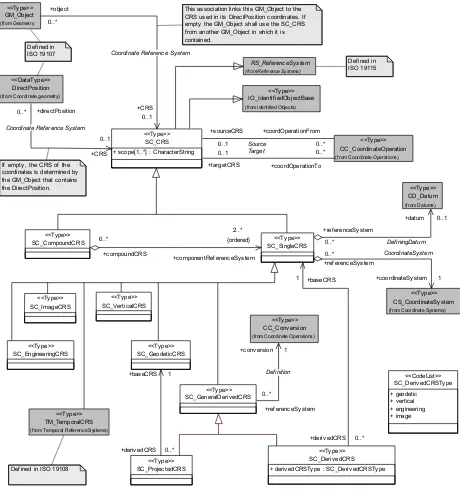
8.3 UML schema for the Coordinate Reference System package
Figure 6 shows the UML class diagram of the SC_CoordinateReferenceSystem package. The definition of the object classes of the package are provided in Tables 4 through 14.
The CRS UML class diagram shows an association named CoordinateSystem from the SC_SingleCRS class to the CS_CoordinateSystem class. This association is included to indicate that all of the subclasses of SC_SingleCRS have a direct association to
CS_CoordinateSystem or one of its subclasses, as later detailed in Figure 8 in Clause 9. In two cases, the multiplicity of the target end of these associations is 1 (mandatory). In three cases, a subclass of SC_SingleCRS has an indirect association through a union class to one of several alternative subclasses of the CS_CoordinateSystem class.
The CRS UML class diagram also shows an association named DefiningDatum from SC_SingleCRS to the CD_Datum class. This association indicates that many, but not all, of the subclasses of SC_SingleCRS have a direct association to CD_Datum or to one of its subclasses, as later shown in Figure 10 in Clause 10. For the subclasses of
SC_ProjectedCRS is modelled separately from SC_DerivedCRS to permit description of its specific association characteristics.
SC_Deriv edCRSTy pe
+ geodetic
+ deriv edCRSTy pe : SC_Deriv edCRSTy pe <<Ty pe>> coordinates is determined by the GM_Object that contains the DirectPosition.
Def ined in ISO 19107
This association links this GM_Object to the CRS used in its DirectPosition coordinates. If empty the GM_Object shall use the SC_CRS f rom another GM_Object in which it is contained.
Def ined in ISO 19115
Table 4 — Defining elements of SC_CRS class
Description: Coordinate reference system which is usually single but may be compound.
Stereotype: Type
Class attribute: Abstract
Inheritance from: RS_ReferenceSystem IO_IdentifiedObjectBase
Association roles: coordinateOperationFrom to CC_CoordinateOperation [0..*], association named Source
coordinateOperationTo to CC_CoordinateOperation [0..*], association named Target
CRS from GM_Object [0..1], association named Coordinate Reference System
(reverse: object to GM_Object [0..*] navigable only from GM_Object – see ISO 19107)
CRS from DirectPosition [0..1], association named Coordinate Reference System
(reverse: directPosition to DirectPosition [0..*] navigable only from DirectPosition – see ISO 19107)
Public attributes:
Attribute name UML identifier Data type Obligation
Maxi-mum Occur-rence
Attribute description
CRS scope scope CharacterString M N Description of usage, or limitations of usage, for
whichh this CRS is valid. If unknown, enter “not known”.
The following 5 attributes are inherited from IO_IdentifiedObjectBase and from RS_ReferenceSystem – see Tables 1 and 3. NOTE As an exception to elsewhere in this Abstract Specification, inherited attributes are included in this class table to allow the CRS name, CRS alias and CRS identifier attributes to be shown together.
Attribute name UML identifier Data type Obligation
Maxi-mum Occur-rence
Attribute description
CRS name name RS_Identifier M 1 This is the primary name for the CRS. Aliases
and other identifiers may be given through the attributes alias and identifier.
CRS alias alias GenericName O N An alias by which this CRS is known.
CRS identifier identifier RS_Identifier O N An identifier which references elsewhere the
CRS's defining information; alternatively an identifier by which this CRS can be referenced.
CRS validity domainOfValidity EX_Extent O N Area or region or time frame in which this
CRS is valid.
CRS remarks remarks CharacterString O 1 Comments on or information about this CRS,
Table 5 — Defining elements of SC_SingleCRS class
Description: Coordinate reference system consisting of one Coordinate System and one Datum (as opposed to a Compound
CRS).
NOTE In ISO 19111:2003, this class was called SC_CoordinateReferenceSystem.
Stereotype: Type
Class attribute: Abstract
Inheritance from: SC_CRS
Association roles: (aggregation) datum to CD_Datum [0..1], association named DefiningDatum
(aggregation) coordinateSystem to CS_CoordinateSystem [1], association named CoordinateSystem
baseCRS from SC_DerivedCRS [1]
(reverse: derivedCRS to SC_DerivedCRS [0..*] navigable only from SC_DerivedCRS – see Table 8)
(aggregation) componentReferenceSystem from SC_CompoundCRS [2..*] {ordered}
(reverse: compoundCRS to SC_CompoundCRS [0..*] navigable only from SC_CompoundCRS – see Table 6)
(associations inherited from SC_CRS)
Public attributes: 6 attributes (CRS name, CRS alias, CRS identifier, CRS validity, CRS scope and CRS remarks) inherited from IO_IdentifiedObjectBase, RS_ReferenceSystem and SC_CRS. See Table 4.
Table 6 — Defining elements of SC_CompoundCRS class
Description: A coordinate reference system describing the position of points through two or more independent single
coordinate reference systems.
NOTE two coordinate reference systems are independent of each other if coordinate values in one cannot be converted or transformed into coordinate values in the other.
Stereotype: Type
Class attribute: Concrete
Inheritance from: SC_CRS
Association roles: (aggregation) componentReferenceSystem to SC_SingleCRS [2..*] {ordered} (associations inherited from SC_CRS)
Public attributes: 6 attributes (CRS name, CRS alias, CRS identifier, CRS validity, CRS scope and CRS remarks) inherited from IO_IdentifiedObjectBase, RS_ReferenceSystem and SC_CRS. See Table 4.
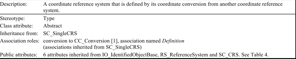
Table 7 — Defining elements of SC_GeneralDerivedCRS class
Description: A coordinate reference system that is defined by its coordinate conversion from another coordinate reference
system.
Stereotype: Type
Class attribute: Abstract
Inheritance from: SC_SingleCRS
Association roles: conversion to CC_Conversion [1], association named Definition
(associations inherited from SC_SingleCRS)
Table 8 — Defining elements of SC_DerivedCRS class
Description: A single coordinate reference system that is defined by its coordinate conversion from another single coordinate
reference system known as the base CRS. The base CRS cannot be a projected coordinate reference system.
Stereotype: Type
Class attribute: Concrete
Inheritance from: SC_GeneralDerivedCRS
Association roles: baseCRS to SC_SingleCRS [1]
(associations inherited from SC_ GeneralDerivedCRS, including …
… (aggregation) coordinateSystem to CS_CoordinateSystem [1], association named CoordinateSystem)
Public attributes: 6 attributes inherited from IO_IdentifiedObjectBase, RS_ReferenceSystem and SC_CRS (CRS name, CRS alias, CRS identifier, CRS validity, CRS scope and CRS remarks – see Table 4), plus:
Attribute name UML identifier Data type Obligation
Maxi-mum
derivedCRStype SC_DerivedCRSType M 1 Type of this derived coordinate reference
system.
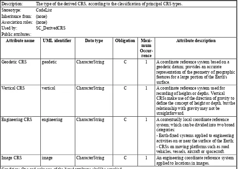
Table 9 — Defining elements of SC_DerivedCRSType class
Description: The type of the derived CRS, according to the classification of principal CRS types.
Stereotype: CodeList
Inheritance from: (none) Association roles: (none)
Used by: SC_DerivedCRS
Public attributes:
Attribute name UML identifier Data type Obligation
Maxi-mum Occur-rence
Attribute description
Geodetic CRS geodetic CharacterString C 1 A coordinate reference system based on a
geodetic datum; provides an accurate representation of the geometry of geographic features for a large portion of the Earth's surface.
Vertical CRS vertical CharacterString C 1 A coordinate reference system used for
recording of heights or depths. Vertical CRSs make use of the direction of gravity to define the concept of height or depth, but the relationship with gravity may not be straightforward.
Engineering CRS engineering CharacterString C 1 A contextually local coordinate reference
system; which can be divided into two broad categories:
- Earth-fixed systems applied to engineering activities on or near the surface of the Earth; - CRSs on moving platforms such as road vehicles, vessels, aircraft or spacecraft.
Image CRS image CharacterString C 1 An engineering coordinate reference system
Table 10 — Defining elements of SC_GeodeticCRS class
Description: A coordinate reference system associated with a geodetic datum.
Stereotype: Type
Class attribute: Concrete
Inheritance from: SC_SingleCRS
Association roles: (aggregation) datum to CD_GeodeticDatum [1], association named DefiningDatum
(aggregation) coordinateSystem to CS_GeodeticCS [1], association named CoordinateSystem
baseCRS from ProjectedCRS [1]
(reverse: derivedCRS to SC_ProjectedCRS [0..*] navigable only from SC_ProjectedCRS – see Table 11)
(associations inherited from SC_SingleCRS)
Public Attributes: 6 attributes (CRS name, CRS alias, CRS identifier, CRS validity, CRS scope and CRS remarks) inherited from IO_IdentifiedObjectBase, RS_ReferenceSystem and SC_CRS. See Table 4.
Table 11 — Defining elements of SC_ProjectedCRS class
Description: A derived coordinate reference system which has a geodetic coordinate reference system as its base CRS and is
converted using a map projection.
Stereotype: Type
Class attribute: Concrete
Inheritance from: SC_GeneralDerivedCRS
Association roles: baseCRS to SC_GeodeticCRS [1]
(aggregation) coordinateSystem to CS_CartesianCS [1], association named CoordinateSystem
(associations inherited from SC_ GeneralDerivedCRS)
Public Attributes: 6 attributes (CRS name, CRS alias, CRS identifier, CRS validity, CRS scope and CRS remarks) inherited from IO_IdentifiedObjectBase, RS_ReferenceSystem and SC_CRS. See Table 4.
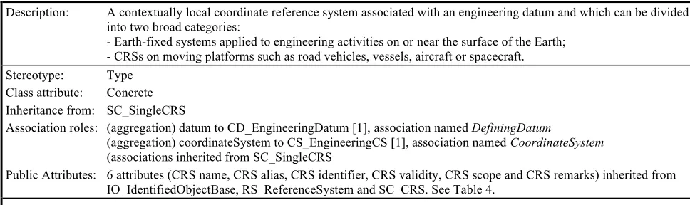
Table 12 — Defining elements of SC_EngineeringCRS class
Description: A contextually local coordinate reference system associated with an engineering datum and which can be divided
into two broad categories:
- Earth-fixed systems applied to engineering activities on or near the surface of the Earth; - CRSs on moving platforms such as road vehicles, vessels, aircraft or spacecraft.
Stereotype: Type
Class attribute: Concrete
Inheritance from: SC_SingleCRS
Association roles: (aggregation) datum to CD_EngineeringDatum [1], association named DefiningDatum
(aggregation) coordinateSystem to CS_EngineeringCS [1], association named CoordinateSystem
(associations inherited from SC_SingleCRS
Table 13 — Defining elements of SC_ImageCRS class
Description: A coordinate reference system associated with an image datum. Image coordinate reference systems are treated as
a separate sub-type because the definition of the associated Image Datum contains two attributes not relevant to other engineering datums.
Stereotype: Type
Class attribute: Concrete
Inheritance from: SC_SingleCRS
Association roles: (aggregation) datum to CD_ImageDatum [1], association named DefiningDatum
(aggregation) coordinateSystem to CS_ImageCS [1], association named CoordinateSystem
(associations inherited from SC_SingleCRS)
Public attributes: 6 attributes (CRS name, CRS alias, CRS identifier, CRS validity, CRS scope and CRS remarks) inherited from IO_IdentifiedObjectBase, RS_ReferenceSystem and SC_CRS. See Table 4.
Table 14 — Defining elements of SC_VerticalCRS class
Description: A 1D coordinate reference system used for recording heights or depths. Vertical CRSs make use of the direction
of gravity to define the concept of height or depth, but the relationship with gravity may not be straightforward. By implication, ellipsoidal heights (h) cannot be captured in a vertical coordinate reference system. Ellipsoidal heights cannot exist independently, but only as inseparable part of a 3D coordinate tuple defined in a geodetic 3D coordinate reference system.
Stereotype: Type
Class attribute: Concrete
Inheritance from: SC_SingleCRS
Association roles: (aggregation) datum to CD_VerticalDatum [1], association named DefiningDatum
(aggregation) coordinateSystem to CS_VerticalCS [1], association named CoordinateSystem
(associations inherited from SC_SingleCRS)
Public Attributes: 6 attributes (CRS name, CRS alias, CRS identifier, CRS validity, CRS scope and CRS remarks) inherited from IO_IdentifiedObjectBase, RS_ReferenceSystem and SC_CRS. See Table 4.
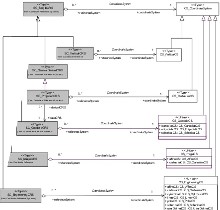
9 Coordinate System package
9.1 Introduction
In this Abstract Specification, the Coordinate System package models two main concepts: coordinate system and coordinate system axis.
9.2 Coordinate system
A coordinate system shall be composed of a non-repeating sequence of coordinate system axes. One coordinate system may be used by multiple coordinate reference systems. The dimension of the coordinate space, the names, the units of measure, the directions and sequence of the axes all shall be part of the coordinate system definition. The number of axes shall be equal to the dimension of the space of which it describes the geometry. It is therefore not permitted to supply a coordinate tuple with two heights of different
definition.
In this Abstract Specification, coordinate systems shall be divided into subtypes by the geometric properties of the coordinate space spanned and the geometric properties of the axes themselves (straight or curved; perpendicular or not). Certain subtypes of coordinate system shall be used only with specific subtypes of coordinate reference system as shown in the UML class diagram in Figure 8 and Table 15. For derived CRSs, the constraints on CS association shall be by derived CRS subtype and follow the constraints for the
equivalent subtype of principle CRS.A description of coordinate system subtypes is included in Table 15.
This Abstract Specification additionally allows for user-defined coordinate systems. Each of these shall be used with one of the coordinate reference system subtypes described in Clause 8.
Table 15 — Subtypes of coordinate system and constraints in its relationship with coordinate reference system
CS subtype Description Used with CRS
type(s)
affine two- or three-dimensional coordinate system with straight axes that are not necessarily
orthogonal.
Engineering Image
Cartesian two- or three-dimensional coordinate system which gives the position of points relative to
orthogonal straight axes. All axes shall have the same unit of measure.
Geodetic Projected Engineering Image
cylindrical three-dimensional coordinate system consisting of a polar coordinate system extended by a
straight coordinate axis perpendicular to the plane spanned by the polar coordinate system.
Engineering
ellipsoidal two- or three-dimensional coordinate system in which position is specified by geodetic
latitude, geodetic longitude and (in the three-dimensional case) ellipsoidal height.
Geodetic
linear one-dimensional coordinate system that consists of the points that lie on the single axis
described. Example: usage of the line feature representing a pipeline to describe points on or along that pipeline.
This Abstract Specification only lends itself to be used for simple (=continuous) linear systems. For a more extensive treatment of the subject, particularly as applied to the transportation industry, refer to ISO 19133 [7].
Engineering
polar two-dimensional coordinate system in which position is specified by distance from the
origin and the angle between the line from origin to point and a reference direction.
Engineering
spherical three-dimensional coordinate system with one distance, measured from the origin, and two
angular coordinates. Not to be confused with an ellipsoidal coordinate system based on an ellipsoid ‘degenerated’ into a sphere.
Geodetic Engineering
vertical one-dimensional coordinate system used to record the heights (or depths) of points
dependent on the Earth’s gravity field. An exact definition is deliberately not provided as the complexities of the subject fall outside the scope of this specification.
Vertical
Coordinate systems are described further in B.2.1.
9.3 Coordinate system axis
EXAMPLE 1 The combination {Latitude, Lat, north, degree} would lead to one instance of the object class “coordinate system axis”; the combination {Latitude, j, north, degree} to another instance, the axis abbreviation being different.
In this Abstract Specification, usage of coordinate system axis names shall be constrained by geodetic custom, depending on the coordinate reference system type. These
constraints are shown in Table 16. This constraint shall work in two directions.
EXAMPLE 2 As “geodetic latitude“ and “geodetic longitude” are used as names for coordinate axes forming a
geodetic coordinate reference system, these terms cannot also be used in another context.
Aliases for these constrained names shall be permitted.
Table 16 — Naming constraints for coordinate system axis
CS type When used in
CRS type
Permitted coordinate system axis names
Cartesian geodetic geocentric X, geocentric Y, geocentric Z
Cartesian projected northing or southing, easting or westing
ellipsoidal geodetic geodetic latitude, geodetic longitude, [ellipsoidal height
(if 3D)]
spherical geodetic spherical latitude, spherical longitude, geocentric radius
vertical vertical depth or gravity-related height
Image and engineering coordinate reference systems may make use of names specific to the local context or custom.
Coordinate system axes are described further in B.2.2.
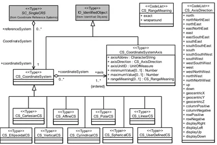
9.4 UML schema for the Coordinate System package
CS_PolarCS
(f rom I dentifi ed Obj ects)
<<Type>>
(from Coordinate Referenc e Systems)
<<Type>>
Figure 7 — CS_CoordinateSystem package
CS_VerticalCS
Table 17 — Defining elements of CS_CoordinateSystem class
Description: A coordinate system (CS) is the non-repeating sequence of coordinate system axes that spans a given coordinate
space. A CS is derived from a set of mathematical rules for specifying how coordinates in a given space are to be assigned to points. The coordinate values in a coordinate tuple shall be recorded in the order in which the coordinate system axes associations are recorded.
Stereotype: Type
Class attribute: Abstract
Inheritance from: IO_IdentifiedObject
Association roles: (aggregation) axis to CS_CoordinateSystemAxis [1..*] {ordered}
(aggregation) coordinateSystem from SC_SingleCRS [1], association named CoordinateSystem
(reverse: referenceSystem to SC_SingleCRS [0..*] navigable only from SC_SingleCRS – see Table 5)
Public attributes: 4 attributes (CS name, CS alias, CS identifier and CS remarks) inherited from IO_IdentifiedObject and IO_IdentifiedObjectBase. See Tables 1 and 2.
Table 18 — Defining elements of CS_CartesianCS class
Description: A two- or three-dimensional coordinate system with orthogonal straight axes. In the 2D case, both axes shall have
the same length unit; in the 3D case, all axes shall have the same length unit. A CartesianCS shall have two or three axis associations; the number of associations shall equal the dimension of the CS.
Stereotype: Type
Class attribute: Concrete
Inheritance from: CS_CoordinateSystem
Association roles: (aggregation) coordinateSystem from SC_ProjectedCRS [1], association named CoordinateSystem
(reverse: referenceSystem to SC_ProjectedCRS [0..*] navigable only from SC_ProjectedCRS – see Table 11)
(associations inherited from CS_CoordinateSystem)
Used by: CS_GeodeticCS
CS_EngineeringCS CS_ImageCS
Public attributes: 4 attributes (CS name, CS alias, CS identifier and CS remarks) inherited from IO_IdentifiedObject and IO_IdentifiedObjectBase. See Tables 1 and 2.
Table 19 — Defining elements of CS_AffineCS class
Description: A two- or three-dimensional coordinate system with straight axes that are not necessarily orthogonal. An
AffineCS shall have two or three axis associations; the number of associations shall equal the dimension of the CS.
Stereotype: Type
Class attribute: Concrete
Inheritance from: CS_CoordinateSystem
Used by: CS_EngineeringCS
CS_ImageCS
Table 20 — Defining elements of CS_EllipsoidalCS class
Description: A two- or three-dimensional coordinate system in which position is specified by geodetic latitude, geodetic
longitude, and (in the three-dimensional case) ellipsoidal height. An EllipsoidalCS shall have two or three associations; the number of associations shall equal the dimension of the CS.
Stereotype: Type
Class attribute: Concrete
Inheritance from: CS_CoordinateSystem
Used by: CS_GeodeticCS
Public attributes: 4 attributes (CS name, CS alias, CS identifier and CS remarks) inherited from IO_IdentifiedObject and IO_IdentifiedObjectBase. See Tables 1 and 2.
Table 21 — Defining elements of CS_SphericalCS class
Description: A three-dimensional coordinate system with one distance measured from the origin and two angular coordinates.
Not to be confused with an ellipsoidal coordinate system based on an ellipsoid "degenerated" into a sphere. A SphericalCS shall have three axis associations.
Stereotype: Type
Class attribute: Concrete
Inheritance from: CS_CoordinateSystem
Used by: CS_EngineeringCS
Public attributes: 4 attributes (CS name, CS alias, CS identifier and CS remarks) inherited from IO_IdentifiedObject and IO_IdentifiedObjectBase. See Tables 1 and 2.
Table 22 — Defining elements of CS_CylindricalCS class
Description: A three-dimensional coordinate system consisting of a polar coordinate system extended by a straight coordinate
axis perpendicular to the plane spanned by the polar coordinate system. A CylindricalCS shall have three axis associations.
Stereotype: Type
Class attribute: Concrete
Inheritance from: CS_CoordinateSystem
Used by: CS_EngineeringCS
Public attributes: 4 attributes (CS name, CS alias, CS identifier and CS remarks) inherited from IO_IdentifiedObject and IO_IdentifiedObjectBase. See Tables 1 and 2.
Table 23 — Defining elements of CS_PolarCS class
Description: A two-dimensional coordinate system in which position is specified by the distance from the origin and the angle
between the line from the origin to a point and a reference direction. A PolarCS shall have two axis associations.
Stereotype: Type
Class attribute: Concrete
Inheritance from: CS_CoordinateSystem
Used by: CS_EngineeringCS
Table 24 — Defining elements of CS_LinearCS class
Description: A one-dimensional coordinate system that consists of the points that lie on the single axis described. The
associated coordinate is the distance – with or without offset – from the origin point, specified through the datum definition, to the point along the axis. Example: usage of the line feature representing a pipeline to describe points on or along that pipeline. A LinearCS shall have one axis association.
Stereotype: Type
Class attribute: Concrete
Inheritance from: CS_CoordinateSystem
Used by: CS_EngineeringCS
Public attributes: 4 attributes (CS name, CS alias, CS identifier and CS remarks) inherited from IO_IdentifiedObject and IO_IdentifiedObjectBase. See Tables 1 and 2.
Table 25 — Defining elements of CS_VerticalCS class
Description: A one-dimensional coordinate system used to record the heights or depths of points. Such a coordinate system is
usually dependent on the Earth's gravity field. An exact definition is deliberately not provided as the complexities of the subject fall outside the scope of this document. A VerticalCS shall have one axis association.
Stereotype: Type
Class attribute: Concrete
Inheritance from: CS_CoordinateSystem
Association roles: (aggregation) coordinateSystem from SC_VerticalCRS [1], association named CoordinateSystem
(reverse: referenceSystem to SC_VerticalCRS [0..*] navigable only from SC_VerticalCRS – see Table 14)
(associations inherited from CS_CoordinateSystem)
Public attributes: 4 attributes (CS name, CS alias, CS identifier and CS remarks) inherited from IO_IdentifiedObject and IO_IdentifiedObjectBase. See Tables 1 and 2.
Table 26 — Defining elements of CS_UserDefinedCS class
Description: A two- or three-dimensional coordinate system that consists of any combination of coordinate axes not covered
by any other Coordinate System type. An example is a multilinear coordinate system which contains one coordinate axis that may have any 1D shape which has no intersections with itself. This non-straight axis is supplemented by one or two straight axes to complete a two- or three-dimensional coordinate system. The non-straight axis is typically incrementally non-straight or curved. A UserDefinedCS shall have two or three axis associations; the number of associations shall equal the dimension of the CS.
Stereotype: Type
Class attribute: Concrete
Inheritance from: CS_CoordinateSystem
Used by: CS_EngineeringCS
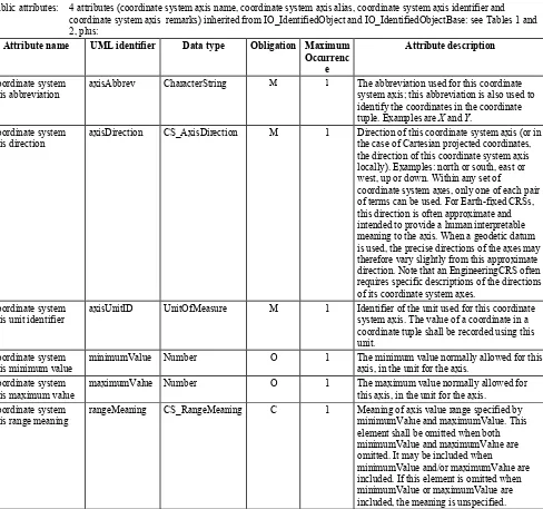
Table 27 — Defining elements of CS_CoordinateSystemAxis class
Description: Definition of a coordinate system axis.
Stereotype: Type
Class attribute: Concrete
Inheritance from: IO_IdentifiedObject
Association roles: (aggregation) axis from CS_CoordinateSystem [1..*] {ordered}
(reverse: coordinateSystem to CS_CoordinateSystem [0..*] navigable only from CS_CoordinateSystem – see Table 17)
Public attributes: 4 attributes (coordinate system axis name, coordinate system axis alias, coordinate system axis identifier and coordinate system axis remarks) inherited from IO_IdentifiedObject and IO_IdentifiedObjectBase: see Tables 1 and 2, plus:
Attribute name UML identifier Data type Obligation Maximum
Occurrenc e
Attribute description
Coordinate system axis abbreviation
axisAbbrev CharacterString M 1 The abbreviation used for this coordinate
system axis; this abbreviation is also used to identify the coordinates in the coordinate tuple. Examples are X and Y.
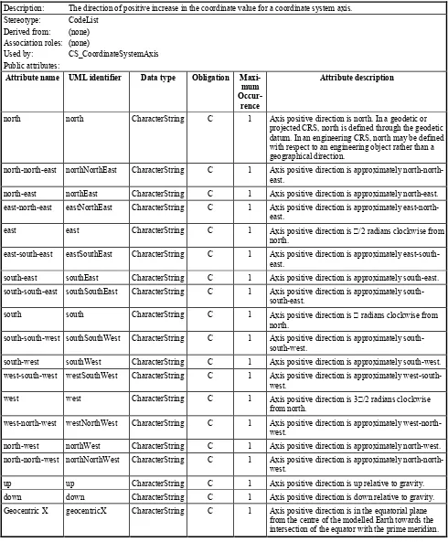
Coordinate system axis direction
axisDirection CS_AxisDirection M 1 Direction of this coordinate system axis (or in
the case of Cartesian projected coordinates, the direction of this coordinate system axis locally). Examples: north or south, east or west, up or down. Within any set of
coordinate system axes, only one of each pair of terms can be used. For Earth-fixed CRSs, this direction is often approximate and intended to provide a human interpretable meaning to the axis. When a geodetic datum is used, the precise directions of the axes may therefore vary slightly from this approximate direction. Note that an EngineeringCRS often requires specific descriptions of the directions of its coordinate system axes.
Coordinate system axis unit identifier
axisUnitID UnitOfMeasure M 1 Identifier of the unit used for this coordinate
system axis. The value of a coordinate in a coordinate tuple shall be recorded using this unit.
Coordinate system axis minimum value
minimumValue Number O 1 The minimum value normally allowed for this
axis, in the unit for the axis. Coordinate system
axis maximum value
maximumValue Number O 1 The maximum value normally allowed for
this axis, in the unit for the axis. Coordinate system
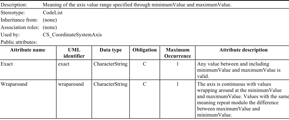
axis range meaning
rangeMeaning CS_RangeMeaning C 1 Meaning of axis value range specified by
minimumValue and maximumValue. This element shall be omitted when both minimumValue and maximumValue are omitted. It may be included when