Full paper for ACED2012
DEVELOPMENT AND STUDY ON TRANSFORMER
CHARACTERISTICS OF A HIGH REPETITION PULSE GENERATOR
Muhammad Abu Bakar SIDIK1,3, HAMIZAH Shahroom1, Hussein AHMAD1, Zolkafle BUNTAT1, Zafar IQBAL1, A. S. Samosir2, Zainuddin NAWAWI3, Muhammad 'Irfan JAMBAK3
1
Insitute of High Voltage and Current (IVAT), Faculty of Electrical Engineering, Universiti Teknologi Malaysia, 81310 Skudai, Johor, Malaysia
2
Department of Energy Conversion, Faculty of Electrical Engineering, Universiti Teknologi Malaysia 3
Department of Electrical Engineering, Faculty of Engineering, Universitas Sriwijaya 30662 Indralaya, Ogan Ilir, South Sumatera, Indonesia
Email: [email protected]
Keywords : Pulse generator, High repetition, IGBT
Abstract: High repetition pulse/ high frequency
generators are of great interest for scientific and technological applications, including high voltage devices. This paper addresses the design and development of a high repetition pulse generator using a PIC microcontroller (PIC 16F877A). The PIC microcontroller generates two PWM pulses to drive the IGBTs through the optocouplers, which can perform fast switching in high voltage devices with low switching losses. The voltage and current supplied by the optocouplers make it perfectly suitable for the driving operations of IGBTs. Experiments were carried out to test its efficiency, and the waveforms of high repetition pulse frequency were observed by oscilloscope. The results of its operation present that the system could be used in the frequency range 2kHz < f < 200kHz. The system was also simulated by a Matlab Simulink model, in which two types of transformer were introduced to predict its validity in real operation with high voltage devices. The simulated results of the designed pulse generator show applications, biological and medical applications, chemical industries and food industries, such as in ozone generation [1], electroperturbation effects [2], clinical electrochemotherapy [3], ultrasound systems [4], environmental protection [5], inactivation of naturally grown microorganisms in orange juice [6], atmosphere plasma [7], methanne conversion rates [8] and many more. Many types of high pulse generator for high voltage applications are commercially available, however alternative methods are still being sought for cost-effective solutions to all the above-mentioned applications. The use of PIC microcontrollers has become popular in power electronics which can generate pulse width modulation (PWM) signals with high pulse frequency. High frequencies up to several kilohertz are also possible with power
electronic switching devices such as MOSFET’s and IGBT’s. The
PIC 16F877A microcontroller is chosen for the development of
high pulse frequency because of its low cost, ease in development and fast response. The microcontroller can vary the frequency signal that controls the applied voltage on the gate drive IGBT’s, which requires the PWM frequency at the output. Furthermore, PIC 16F877A is highly portable, has a low current consumption and a high performance RISC CPU, and it has an operating speed of 20MHz [9]. The IGBT gate driver optocoupler is selected because it has the highest switching speed to drive the IGBT. The insulated gate drive transistor (IGBT) is a highly efficient semiconductor switching device since it has a good performance in high voltage switching and low switching losses.
The industrial environment for the application of high pulse generators to produce high voltage is currently expanding. Two different technologies have been developed in the past, in which the pulse is obtained directly through high voltage or the pulses are generated at the low medium link and then amplified for the pulse transformer [10]. The technique can be used to generate high voltages by implementing a combination of the microcontroller and semiconductor switching devices with the use of step up transformers such as a neon transformer, flyback transformer, ignition coil transformer, and others. Secondly, the transformer is used to further increase the voltage pulses which are limited due to the existence of parasitic elements that worsen the pulse shape [11].
with high voltage devices. Details of the software and hardware of its design and operation have been discussed.
II. DESIGN OF A HIGH REPETITION PULSE
GENERATOR
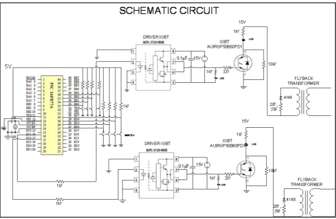
The schematic diagram of the developed circuit is shown in Fig.1. A source code using microBasic Pro for PIC was developed
Figure 1. Circuit schematic
TABLE 1. Hardware component
Component Description
Microcontroller SK40C (PIC start up kit) , PIC 16F877A
Driver IGBT ACPL-312U-000E
IGBT AUIRGP50B60PD1
Capacitor 0.1µF
Resistor 1kΩ,33Ω,10kΩ,20Ω
Diode 4148
The PIC microcontroller was used to produce two PWM’s signal which can be used for two applications in one circuit. One of the tasks of the microcontroller program was to vary the duty cycle, and the other was to vary the frequency. The duty cycle can be varied from 0% to 100% by using the switch, and the frequency can be changed from 2kHz to 200kHz. The PWM signals from the microcontroller are applied to the IGBT’s gate through gate driver. The current and voltage supplied by this gate driver directly match the IGBT. The oscillograph of the PWM waveform was observed in the high frequency range and also by varying the frequency and duty cycle.
The circuit was designed on a double layer printed circuit board
(a) (b)
Figure 2. (a) Top view (b) Bottom view PCB design
Figure 3. Top view PCB
Figure 4. Bottom view PCB
III. RESULTS
The complete prototype is shown in Figure 5, in which a PCB was attached inside the box. The output on the IGBT was connected to a FBT transformer.
(a)
(b)
Figure 5. Project prototype
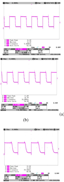
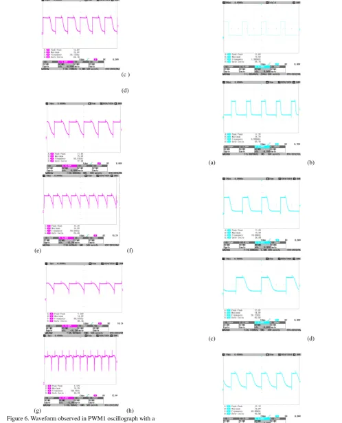
The experimental results of the oscillograph for PWM1 and PWM 2 are shown in Figure 6 and Figure 7 respectively.
(a)
(b)
(c ) (d)
(e) (f)
(g) (h)
Figure 6. Waveform observed in PWM1 oscillograph with a frequency of (a) 5kHz (b) 10kHz (c) 20kHz (d) 30kHz (e) 50kHz
(f) 80kHz (g) 100kHz (h) 200kHz
(a) (b)
(c) (d)
(e) (f)
(g) (h)
Figure 7. Waveform observed in PWM2 oscillograph with a frequency of (a) 2kHz (b) 10kHz (c) 20kHz (d) 30kHz (e) 50kHz
(f) 80kHz (g) 100kHz (h) 200kHz
III. SIMULINK MODEL
A Simulink model of a repetition pulse generator coupled with iron core transformers is developed using MATLAB R2009b to check the reliability of the pulse generator in the case of real devices. The schematic of the Simulink model is shown in Figure 8. The simulated waveform of the pulses produced at the input/output of the IGBT were obtained and fed into the real transformer. The values of inductance, resistance and capacitance of the real transformer were measured with a LCR meter at the primary and secondary winding of the transformer. The simulation was run with these values input in the Simulink model. Three different iron core transformers were used in the simulation, the results of which are depicted below. A block diagram of the Simulink model is shown in Figure 8 [13].
Figure 8. Simulation block diagram
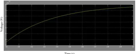
The simulation results for different types of iron core transformer are shown in Figure 9 and Figure 10. The values of different parameters of iron core transformers were changed accordingly in the Matlab Simulink model, and the data were recorded manually to obtain the waveform, which are depicted in the Figures 9–10
Figure 9.Iron core transformer KSSB 57X19
V
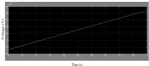
The simulation results for the Diamond FTM-063G7 ignition coil transformer are shown in Figure 11, while Figure 12 depicts the
Time (s)
Figure 12. Ignition coil transformer – CIT-118 12V 4X2
V. DISCUSSION
On the basis of experimental results which have been discussed above, the output waveform changes with the high pulse frequency for every increased value of frequency. The PIC microcontroller is successfully used to drive the IGBT, and the implemented design successfully presents a high repetition pulse frequency in the range of 2 kHz< f<200 kHz. The system works well in the applicable frequency range of 2 kHz< f <200 kHz, and if f <2 kHz a message text is displayed in microBasic as “out of range”, while in case of f > 200 kHz it will produce a sinusoidal waveform. It was also observed that when the frequency is over the limit no PWM pulses were obtained.
The pulses show a very obvious spike when the frequency is increased. This occurs because the output at high frequency has a time constant of the circuit which is much shorter than the periodic time of the wave. The output wave from IGBT is not the same as the input wave of the microcontroller but it consists of narrow positive and negative spikes. Moreover, a voltage spike is also due to the rapid rise time of the IGBT [14].
The transient occurred at the falling edge when the frequency is increased to more than 20 kHz. This is caused by the capacitor value or the type of capacitor. Another option that can be used to solve this problem is to change the capacitor with a high frequency capacitor.
The values of peak to peak voltage drop when the frequencies are increased for both PWMs but the value of maximum voltage is almost 15V, which is the same as the supply voltage. However, in pulse discharge applications the peak voltage (Vp) or maximum voltage (Vmax) are the most important to consider, rather than the peak to peak voltage (Vpp). Since the microcontroller has two PWMs output it can be used separately for two different applications as well as a sequence input for one application. This can be done by shifting one of the PWM outputs half a cycle from the other, and then the frequency of the PWM will be doubled.
In practical application, the high pulse generator will be connected to a transformer. A study of two types of step up transformer is shown in Figure 9, Figure 10, Figure 11 and Figure 12. The waveform of the iron core transformer in Figure 9 and Figure 10 shows that the voltage increases exponentially with time and then becomes constant when the limit is exceeded. Usually the iron core transformer is used in low frequency mode operations. For this operation the frequency was set in the range of 2 kHz to 200 kHz. At high frequency the iron core is saturated.
In the case of the ignition coil transformer, the waveforms shown in Figure 11 and Figure 12 have a linear trend. The performance of the ignition coil transformer is better than the other iron core transformer. This is because the linear behaviour of this kind of
generator using a PIC 16F877A microcontroller by varying the PWM signal from the microcontroller to several PWM frequencies and duty cycles. The development of a high repetition pulse generator was successfully achieved. The effect of changing the frequency and duty cycle was observed in the waveform on the oscilloscope. The high voltage characteristic of the transformer of different iron core transformers was verified through simulation results, in which the ignition coil transformer is found to be a suitable transformer that can be used in this high frequency range. On the basis of the analysis of the test data it can be concluded that the applicable frequency range for this system is 2kHz< f <200kHz. This system is applicable for high voltage applications such as switching purposes..
ACKNOWLEDGEMENTS
The authors gratefully acknowledge the support extended by Ministry of Higher Education (MOHE), Malaysia and Universiti Teknologi Malaysia on the Fundamental Research Grant Scheme (FRGS), No. R.J130000.7823.4F054 to carry out this work.
REFERENCES
[1] M. Facta, Z. Salam, Z. Buntat, “The development of ozone generation with low power consumption,” in Proc. Conf. Innovative in Intelligent
Systems and Industrial Application (CITISIA), 2009, pp. 440–445.
[2] T. Tang, F. Wang, A. Kuthi, M.A. Gundersen, “Diode opening switch based nanosecond high voltage pulse generators for biological and medical applications,” IEEE Trans. Dielectr. Electr. Insul., vol. 14, electrochemotherapy,” Bioelectrochemistry, vol. 65, pp. 121–128, 2005.
[4] X. Xu, J.T. Yen, K.K. Shung, “A low cost bipolar pulse generator for high frequency ultrasound applications,” IEEE Trans. Ultrason. Ferroelectr. Freq. Control, vol. 54, no. 2, pp. 443–447, 2007. [5] G. Jun, Q. Jianxin, C. Yin, X. Xiao J. Lianjinxin, “Development of
high power, high frequency and high voltage supply system for electrostatic precipitator,” in Int. Conf. Electrostatic Precipitation (ICESP X), 2006.
[6] A.H. El Hag, S.H. Jayaram, M.W. Griffiths, “Inactivation of naturally grown microorganism in orange juice using pulsed electric fields,”
IEEE Trans. Plasma Sci., vol. 34, no. 4, pp. 1412–1415, 2006.
[7] M.T. Tsai, “Design and implementation of high voltage high frequency pulse power generation system for plasma applications,” in Int. Conf. Power Electronics and Drive Systems (PEDS 2009), pp. 1556–1560, 2009.
[9] N.K. Mohanty, R. Muthu, “Microcontroller based PWM controlled four switch three phase inverter fed induction motor drive,” Serbian J. Electr. Eng., vol. 7, no. 2, pp. 195–204, 2010.
[10] L. Heinemann, Kjell Porle, Per Ranstad, “Design of a high pulse voltage generator for electrostatic precipitators using magnetic switching technique,” in Proc. 12th Ann. Applied Power Electronics
Conf. Expo. (APEC '97), pp. 948–952, 1997.
[11] D.M Goebel, “Chapter 8: Pulse technology,” in A. Anders (ed.),
Handbook of Plasma Immersion Ion Implantation and Deposition, 1st
edition, New York: John Wiley & Son, 2000, p. 760, ISBN 0-471-24698-0.
[12] G. Grandi, M.K. Kazimierczuk, A. Massarini, “Model of laminated iron core inductors for high frequencies,” IEEE Trans. Magnetics, vol. 40, no. 4, pp. 1839-1845, 2004.
[13] S.M. Zafar Iqbal, Z. Buntat, M.A.B. Sidik, “Simulink model for optimum output of transformers having different core materials using frequency response analysis,” unpublished.
[14] G. Skibinski, w. Maslowski, J. Pankau, “Installation Consideartion for
IGBT AC Drives,” in Industry Technical Conf. Textile, Fiber, and
Film, pp. 1-12,, 1997.