Chapter 16
Multimedia Network Communications
and Applications
16.1 Quality of Multimedia Data Transmission
16.2 Multimedia over IP
16.3 Multimedia over ATM Networks
16.4 Transport of MPEG-4
16.5 Media-on-Demand (MOD)
16.6 Further Exploration
1 Li & DrewcPrentice Hall 2003
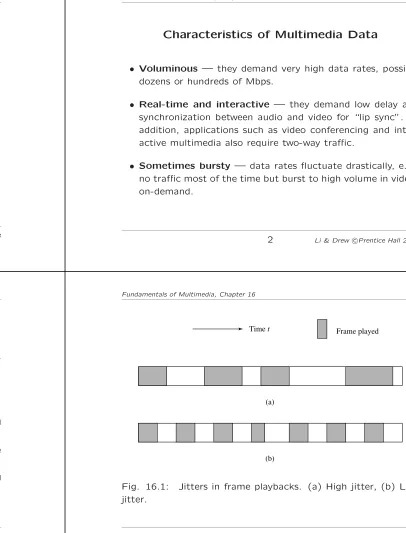
Characteristics of Multimedia Data
• Voluminous — they demand very high data rates, possibly dozens or hundreds of Mbps.
• Real-time and interactive — they demand low delay and synchronization between audio and video for “lip sync”. In addition, applications such as video conferencing and inter-active multimedia also require two-way traffic.
• Sometimes bursty — data rates fluctuate drastically, e.g., no traffic most of the time but burst to high volume in video-on-demand.
2 Li & DrewcPrentice Hall 2003
Fundamentals of Multimedia, Chapter 16
16.1 Quality of Multimedia Data Transmission
•
Quality of Service (QoS)
depends on many
pa-rameters:
– Data rate: a measure of transmission speed.
– Latency (maximum frame/packet delay): maximum time needed from transmission to reception.
– Packet loss or error: a measure (in percentage) of error rate of the packetized data transmission.
– Jitter: a measure of smoothness of the audio/video playback, related to the variance of frame/packet delays.
– Sync skew: a measure of multimedia data synchronization.
Fundamentals of Multimedia, Chapter 16
Frame played Timet
(a)
(b)
Multimedia Service Classes
• Real-Time (also Conversational): two-way traffic, low la-tency and jitter, possibly with prioritized delivery, e.g., voice telephony and video telephony.
• Priority Data: two-way traffic, low loss and low latency, with prioritized delivery, e.g., E-commerce applications.
• Silver: moderate latency and jitter, strict ordering and sync. One-way traffic, e.g., streaming video, or two-way traffic (alsoInteractive), e.g., web surfing, Internet games.
• Best Effort (also Background): no real-time requirement, e.g., downloading or transferring large files (movies).
• Bronze: no guarantees for transmission.
5 Li & DrewcPrentice Hall 2003
Table 16.1: Requirement on Network Bandwidth / Bit-rate
Application Speed Requirement
Telephone 16 kbps
Audio-conferencing 32 kbps
CD-quality audio 128–192 kbps Digital music (QoS) 64–640 kbps
H. 261 64 kbps–2 Mbps
H. 263 <64 kbps
DVI video 1.2–1.5 Mbps
MPEG-1 video 1.2–1.5 Mbps
MPEG-2 video 4–60 Mbps
HDTV (compressed) >20 Mbps HDTV (uncompressed) >1 Gbps MPEG-4 video-on-demand (QoS) 250–750 kbps Videoconferencing (QoS) 384 kbps–2 Mbps
6 Li & DrewcPrentice Hall 2003
Fundamentals of Multimedia, Chapter 16
Table 16.2: Tolerance of Latency and Jitter in Digital Audio and Video
Application Avg Latency Avg Jitter
Tolerance Tolerance
(msec) (msec)
Low-end videoconf. (64 kbps) 300 130 Compressed voice (16 kbps) 30 130 MPEG NTSC video (1.5 Mbps) 5 7
MPEG audio (256 kbps) 7 9
HDTV video (20 Mbps) 0.8 1
Fundamentals of Multimedia, Chapter 16
Perceived QoS
• Although QoS is commonly measured by the above technical parameters, QoS itself is a “collective effect of service performances that determine the degree of satisfaction of the user of that service”.
• In other words, it has everything to do with how the user
perceives it. For example, in real-time multimedia:
– Regularity is more important than latency (i.e., jitter and quality fluc-tuation are more annoying than slightly longer waiting).
– Temporal correctness is more important than the sound and picture quality (i.e., ordering and synchronization of audio and video are of primary importance).
QoS for IP Protocols
• IP is a best-effort communications technology — hard to
provide QoS over IP by current routing methods.
– Abundant bandwidth improves QoS, but unlikely to be available ev-erywhere over a complex networks.
• DiffServ (Differentiated Service) uses DiffServ code [TOS
(Type of Service) octet in IPv4 packet, and Traffic Class octet in IPv6 packet] to classify packets to enable their dif-ferentiated treatment.
– Widely deployed in intra-domain networks and enterprise networks as it is simpler and scales well.
– Emerging as the de-facto QoS technology in conjunction with other QoS.
9 Li & DrewcPrentice Hall 2003
QoS for IP Protocols
(Cont’d)• MPLS (Multiple Protocol Label Switching) facilitates the
marriage of IP to OSI Layer 2 technologies.
– Creates tunnels: Label Switched Paths (LSP) — IP network becomes connection-oriented.
– Main advantages of MPLS:
1. Support Traffic Engineering (TE), which is used essentially to con-trol traffic flow.
2. Support VPN (Virtual Private Network).
3. Both TE and VPN help delivery of QoS for multimedia data.
10 Li & DrewcPrentice Hall 2003
Fundamentals of Multimedia, Chapter 16
Prioritized Delivery
Used to alleviate the perceived deterioration (high packet loss or error rate) in network congestion.
• Prioritization for types of media:
– Transmission algorithms can provide prioritized delivery to different media.
• Prioritization for uncompressed audio:
– PCM audio bitstreams can be broken into groups of everynth sample. • Prioritization for JPEG image:
– The differentscansin Progressive JPEG and different resolutions of the image in Hierarchical JPEG can be given different priorities. • Prioritization for compressed video:
– Set priorities to minimize playback delay and jitter by giving highest priority to I-frames for their reception, and lowest priority to B-frames.
Fundamentals of Multimedia, Chapter 16
16.2 Multimedia over IP
Abroadcastmessage is sent to all nodes in the domain, aunicast
message is sent to only one node, and a multicast message is sent to a set of specified nodes.
• IP-Multicast:
– Anonymous membership: the source host multicasts to one of the IP-multicast addresses — doesn’t know who will receive.
– Potential problem: too many packets will be traveling and alive in the network — use time-to-live (TTL) in each IP packet.
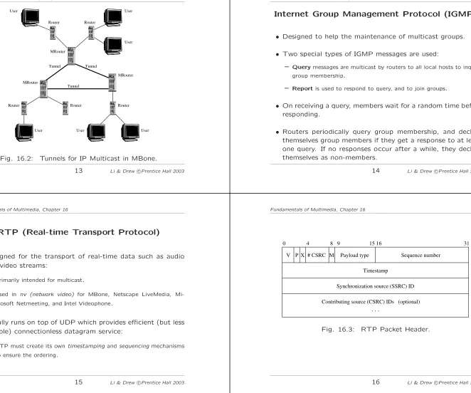
• MBone (Multicast Backbone) — based on the IP-multicast technology:
– Used for audio and video conferencing on the Internet.
Tunnel Tunnel Tunnel
MRouter Router
MRouter
Router
Router
Router Router MRouter
User User User
User
User User
Fig. 16.2: Tunnels for IP Multicast in MBone.
13 Li & DrewcPrentice Hall 2003
Internet Group Management Protocol (IGMP)
• Designed to help the maintenance of multicast groups.
• Two special types of IGMP messages are used:
– Querymessages are multicast by routers to all local hosts to inquire group membership.
– Reportis used to respond to query, and to join groups.
• On receiving a query, members wait for a random time before responding.
• Routers periodically query group membership, and declare themselves group members if they get a response to at least one query. If no responses occur after a while, they declare themselves as non-members.
14 Li & DrewcPrentice Hall 2003
Fundamentals of Multimedia, Chapter 16
RTP (Real-time Transport Protocol)
• Designed for the transport of real-time data such as audio and video streams:
– Primarily intended for multicast.
– Used in nv (network video) for MBone, Netscape LiveMedia, Mi-crosoft Netmeeting, and Intel Videophone.
• Usually runs on top of UDP which provides efficient (but less reliable) connectionless datagram service:
– RTP must create its owntimestamping andsequencingmechanisms to ensure the ordering.
Fundamentals of Multimedia, Chapter 16
Sequence number
Timestamp
Synchronization source (SSRC) ID
0 15 31
Payload type 9
. . .
8
Contributing source (CSRC) IDs (optional) # CSRC
P V
4
X M
16
Additional Parameters in RTP Header
• Payload Type: indicates the media data type as well as its encoding scheme.
– E.g., PCM, H.261/H.263, MPEG 1, 2, and 4 audio/video, etc.
• Timestamp: records the instant when the first octet of the packet is sampled.
– With the timestamps, the receiver can play the audio/video in proper timing order and synchronize multiple streams.
• Sequence Number: complements the function of times-tamping.
– Incremented by one for each RTP data packet sent so to ensure that the packets can be reconstructed in order by the receiver.
17 Li & DrewcPrentice Hall 2003
Additional Parameters in RTP Header
(Cont’d)• Synchronization Source (SSRC) ID: for identifying sources of multimedia data.
– Incremented by one for each RTP data packet sent so to ensure that the packets can be reconstructed in order by the receiver.
• Contributing Source (CSRC) ID: for source identification of contributors, e.g., all speakers in an audio conference.
18 Li & DrewcPrentice Hall 2003
Fundamentals of Multimedia, Chapter 16
RTCP (Real Time Control Protocol)
• A companion protocol of RTP:
– Monitors QoS in providing feedback to the server (sender) and conveys information about the participants of a multi-party conference.
– Provides the necessary information for audio and video synchronization.
• RTP and RTCP packets are sent to the same IP address (multicast or unicast) but on different ports.
Fundamentals of Multimedia, Chapter 16
Five types of RTCP packets
1. RR (Receiver Report)— to provide quality feedback (num-ber of last packet received, num(num-ber of lost packets, jitter, timestamps for calculating round-trip delays).
2. SR (Sender Report) — to provide information about the reception of RR, number of packets/bytes sent, etc.
3. SDES (Source Description)— to provide information about the source (e-mail address, phone number, full name of the participant).
4. Bye — the end of participation.
RSVP (Resource ReSerVation Protocol)
• Developed to guarantee desirable QoS, mostly for multicast although also applicable to unicast.
– A general communication model supported by RSVP con-sists ofmsenders andnreceivers, possibly in various mul-ticast groups (e.g. Fig. 16.4(a)).
• The most important messages of RSVP:
(1) A Path message is initiated by the sender, and contains information about the sender and the path (e.g., the pre-vious RSVP hop).
(2) AResvmessage is sent by a receiver that wishes to make a reservation.
21 Li & DrewcPrentice Hall 2003
Main Challenges of RSVP
(a) There can be a large number of senders and receivers com-peting for the limited network bandwidth.
(b) The receivers can be heterogeneous in demanding different contents with different QoS.
(c) They can be dynamic by joining or quitting multicast groups at any time.
22 Li & DrewcPrentice Hall 2003
Fundamentals of Multimedia, Chapter 16
(a)
S1 S2
R1 R2 R3
C D
B A
(b)
(d) (c)
S1 S2
R1 R2 R3
C D
B A
S1 S2
R1 R2 R3
C D
B A
S1 S2
R1 R2 R3
C D
B A
Fig. 16.4: A scenario of network resource reservation with RSVP.
Fundamentals of Multimedia, Chapter 16
About the Example in Fig. 16.4
• Fig. 16.4 depicts a simple network with 2 senders (S1, S2), three receivers (R1, R2, and R3) and 4 routers (A, B, C, D): 1. In (a),Path messages are sent by both S1 and S2 along
their paths to R1, R2, and R3.
2. In (b) and (c), R1 and R2 send outResv messages to S1 and S2 respectively to make reservations for S1 and S2 resources. Note that from C to A, two separate channels must be reserved since R1 and R2 requested different data streams.
RTSP (Real Time Streaming Protocol)
• Streaming Audio and Video:
– Audio and video data that are transmitted from astored media server
to the client in a data stream that is almost instantly decoded.
• RTSP Protocol: for communication between a client and a stored media server (Fig. 16.5).
1. Requesting presentation description: the client issues a DESCRIBE request to the Stored Media Server to obtain the presentation descrip-tion — media types, frame rate, resoludescrip-tion, codec, etc.
2. Session setup: the client issues a SETUP to inform the server of the destination IP address, port number, protocols, TTL (for multicast).
3. Requesting and receiving media: after receiving a PLAY, the server started to transmit streaming audio/video data using RTP.
4. Session closure: TEARDOWN closes the session.
25 Li & DrewcPrentice Hall 2003
GET request
RTCP RTP audio
RTP video SETUP response
TEARDOWN response GET response
OPTIONS response
PLAY response
PAUSE response
TEARDOWN request PAUSE request
PLAY request SETUP request OPTIONS request
C l i e n t
M e d i a
S e r v e r
Fig. 16.5: A possible scenario of RTSP operations.
26 Li & DrewcPrentice Hall 2003
Fundamentals of Multimedia, Chapter 16
Internet Telephony
• Main advantages of Internet telephony over POTS (Plain
Old Telephone Service):
– Uses packet-switching — network usage is much more ef-ficient (voice communication is bursty and VBR encoded). – With the technologies of multicast or multipoint commu-nication, multi-party calls are not much more difficult than two-party calls.
– With advanced multimedia data compression techniques, various degrees of QoS can be supported and dynamically adjusted according to the network traffic.
– Good graphics user interfaces can be developed to show available features and services, monitor call status and progress, etc.
Fundamentals of Multimedia, Chapter 16
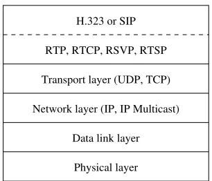
Internet Telephony
(Cont’d)• As shown in Fig. 16.6, the transport of real-time audio (and video) in Internet telephony is supported by RTP (whose control protocol is RTCP).
RTP, RTCP, RSVP, RTSP
Network layer (IP, IP Multicast)
Data link layer
Physical layer Transport layer (UDP, TCP)
H.323 or SIP
Fig. 16.6: Network Protocol Structure for Internet Telephony.
29 Li & DrewcPrentice Hall 2003
H.323
• A standard for packet-based multimedia communication ser-vices over networks that do not provide a guaranteed QoS.
– It specifiessignaling protocols, and describes terminals, multipoint control units (for conferencing) and gateways for the integration of Internet telephony withGSTNdata terminals.
• The H.323 signaling process consists of two phases:
1. Call setup: The caller sends the gatekeeper (GK) a RAS Admission Request (ARQ) message which contains the name and phone number of the callee.
2. Capability exchange: An H.245 control channel will be established, of which the first step is to exchange capabilities of both the caller and callee.
30 Li & DrewcPrentice Hall 2003
Fundamentals of Multimedia, Chapter 16
SIP (Session Initiation Protocol)
• An application-layer control protocol in charge of the estab-lishment and termination of sessions in Internet telephony.
– SIP is a text-based protocol, also a client-server protocol.
• SIP can advertise its session using email, news group, web pages or directories, orSAP — a multicast protocol.
• The methods(commands) for clients to invoke:
– INVITE: invites callee(s) to participate in a call.
– ACK: acknowledges the invitation.
– OPTIONS: enquires media capabilities without setting up a call.
– CANCEL: terminates the invitation.
– BYE: terminates a call.
– REGISTER: sends user’s location info to a Registrar (a SIP server).
Fundamentals of Multimedia, Chapter 16
Scenario of a SIP Session
• Fig. 16.7 A scenario when a caller initiates a SIP session: – Step 1. Caller sends an ”INVITE [email protected]” to the
local Proxy server P1.
– Step 2. The proxy uses its DNS (Domain Name Service) to locate the server for [email protected] and sends the re-quest to it.
– Step 3,4. [email protected] is current not logged on the server. A request is sent to the nearby Location server. John’s current address [email protected] is located.
– Step 6. Try the next Proxy server P2 for [email protected]. – Step 7,8. P2 consults its Location server and obtains
John’s local address john [email protected].
– Step 9,10. The next-hop Proxy server P3 is contacted, it in turn forwards the invitation to where the client (callee) is.
– Step 11-14. John accepts the call at his current location (at work) and the acknowledgments are returned to the caller.
33 Li & DrewcPrentice Hall 2003
Redirect server
Location server
Location server
SIP client (callee) SIP client (caller)
4
5
6
9 12 13 14
3
2 1
10
11 Proxy server (P3)
Proxy server (P2) Proxy
server (P1)
8 7
Fig 16.7: A possible scenario of SIP session initiation.
34 Li & DrewcPrentice Hall 2003
Fundamentals of Multimedia, Chapter 16
16.3 Multimedia over ATM Networks
• Video Bit-rates over ATM:
– CBR (Constant Bit Rate): if the allocated bit-rate of CBR is too low, then cell loss and distortion of the video content are inevitable.
– VBR (Variable Bit Rate): the most commonly used video bit-rate for compressed video, can be further divided into:
∗ rt-VBR(real-time Variable Bit Rate): for compressed video.
∗ nrt-VBR(non real-time Variable Bit Rate): for specified QoS.
– ABR (Available Bit Rate): data transmission can be backed off or buffered due to congestion. Cell loss rate and minimum cell data rate can sometimes be specified.
– UBR(Unspecified Bit Rate): no guarantee on any quality parameter.
Fundamentals of Multimedia, Chapter 16
ATM Adaptation Layer (AAL)
• Converts various formats of user data into ATM data streams and vice versa.
• Different types of protocols of (AAL):
– AAL Type 1: supports real-time, constant bit rate (CBR), connection-oriented data streams.
– AAL Type 2: intended for variable bit rate (VBR) compressed video and audio (inactive).
– AAL Types 3 and 4: have been combined into one type — AAL Type 3/4. It supports variable bit rate (VBR) of either connection-oriented or connectionless general (non real-time) data services.
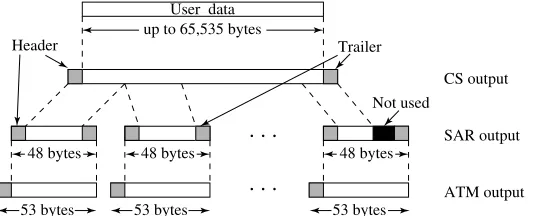
User data
48 bytes 48 bytes 48 bytes
53 bytes 53 bytes
53 bytes
. . .
. . .
HeaderNot used
CS output
SAR output
ATM output Trailer
up to 65,535 bytes
Fig. 16.8: Headers and Trailers added at the CS and SAR sublayers
• Headers and trailers are added to the original user data at the CS (Con-vergence Sublayer) and SAR (Segmentation And Reassembly sublayer) — eventually form the 53-byte ATM cells with the 5-byte ATM header appended.
37 Li & DrewcPrentice Hall 2003
Table 16.3: Comparison of AAL Types
AAL 1 AAL 3/4 AAL 5
CS Header/Trailer Overhead 0 byte 8 bytes 8 bytes SAR Header/Trailer Overhead 1 or 2 bytes 4 bytes 0 byte SAR Payload 47 or 46 bytes 44 bytes 48 bytes CS Checksum None None 4 bytes SAR Checksum None 10 bits None
• AAL 3/4 has an overhead of designating 4 bytes header/trailer for each SAR cell, whereas AAL 5 has none at this sublayer. Considering the numerous number of SAR cells, this is a substantial saving for AAL 5.
• As part of the SAR trailer, AAL 3/4 has a (short) 10-bit “Checksum” for error checking. AAL 5 does it at the CS and allocates 4 bytes for the Checksum.
38 Li & DrewcPrentice Hall 2003
Fundamentals of Multimedia, Chapter 16
Table 16.4: Support for Digital Video Transmission
Video Requirement Support in ATM Support w/t ATM
Bandwidth Scalable to several Gbps Up to 100 Mbps Latency and Jitter QoS support RSVP
CBR or VBR AAL 1, 2, 5, ISDN and ADSL LAN emulation,
circuit emulation,etc.
Multicasting Multicast switch, or IP-multicast or permanent virtual Protocol Independent
circuit Multicast (PIM)
Fundamentals of Multimedia, Chapter 16
MPEG-2 Convergence to ATM
• The ATM Forum has decided that MPEG-2 will be trans-ported over AAL5:
– Two MPEG-2 packets (each 188 bytes) from the Transport Stream (TS) will be mapped into one AAL-5 SDU (Service Data Unit). • When establishing a virtual channel connection, the following
QoS parameters must be specified: – Maximum cell transfer delay.
– Maximum cell delay.
– Cell Loss Ratio (CLR).
– Cell Error Ratio (CER).
Multicast over ATM
• Multicast in ATM networks had several challenges:
– ATM is connection-oriented; hence ATM multicasting needs to set up all multipoint connections.
– QoS in ATM must be negotiated at the connection set-up time and be known to all switches.
– It is difficult to support to-point or multipoint-to-multipoint connections in ATM, because AAL 5 does not keep track of multiplexer number or sequence number.
41 Li & DrewcPrentice Hall 2003
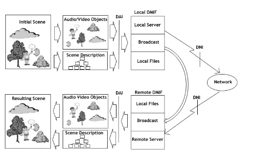
16.4 Transport of MPEG-4
• DMIF in MPEG-4: An interface between multimedia appli-cations and their transport. It supports:
1. Remote interactive network access (IP, ATM, PSTN, ISDN, mobile). 2. Broadcast media (cable or satellite).
3. Local media on disks.
• A single application can run on different transport layers as long as the right DMIF is instantiated.
• Fig. 16.9 shows the integration of delivery through three types of communication mediums.
• MPEG-4 over IP: MPEG-4 sessions can be carried over IP-based protocols such as RTP, RTSP, and HTTP.
42 Li & DrewcPrentice Hall 2003
Fundamentals of Multimedia, Chapter 16
Fig. 16.9: DMIF — the multimedia content delivery integration framework.
Fundamentals of Multimedia, Chapter 16
16.5 Media-on-Demand (MOD)
• Interactive TV (ITV) and Set-top Box (STB)
– ITV supports activities such as:
1. TV (basic, subscription, pay-per-view). 2. Video-on-demand (VOD).
3. Information services (news, weather, magazines, sports events, etc.).
Processing unit
Audio/Video unit
Graphics unit
Peripheral control unit
TV monitor Multimedia Networks
Network interface and communication unit STB
(Set-Top Box)
Disks I/O devices
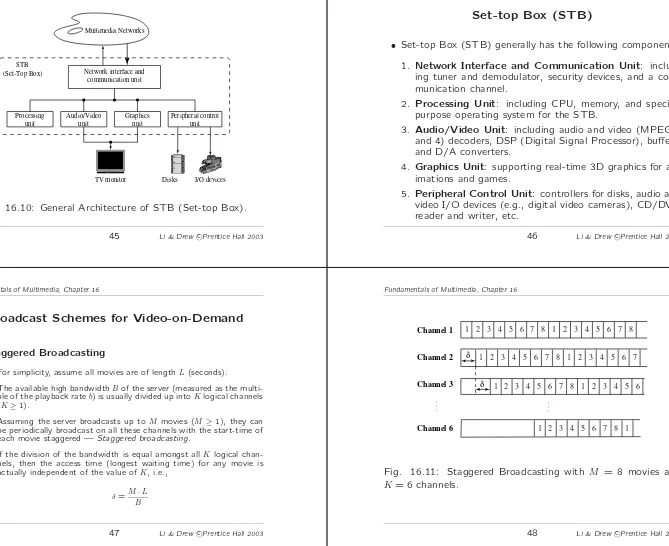
Fig. 16.10: General Architecture of STB (Set-top Box).
45 Li & DrewcPrentice Hall 2003
Set-top Box (STB)
• Set-top Box (STB) generally has the following components: 1. Network Interface and Communication Unit: includ-ing tuner and demodulator, security devices, and a com-munication channel.
2. Processing Unit: including CPU, memory, and special-purpose operating system for the STB.
3. Audio/Video Unit: including audio and video (MPEG-2 and 4) decoders, DSP (Digital Signal Processor), buffers, and D/A converters.
4. Graphics Unit: supporting real-time 3D graphics for an-imations and games.
5. Peripheral Control Unit: controllers for disks, audio and video I/O devices (e.g., digital video cameras), CD/DVD reader and writer, etc.
46 Li & DrewcPrentice Hall 2003
Fundamentals of Multimedia, Chapter 16
Broadcast Schemes for Video-on-Demand
• Staggered Broadcasting
– For simplicity, assume all movies are of lengthL(seconds).
– The available high bandwidthBof the server (measured as the multi-ple of the playback rateb) is usually divided up intoKlogical channels (K≥1).
– Assuming the server broadcasts up toM movies (M≥1), they can be periodically broadcast on all these channels with the start-time of each movie staggered —Staggered broadcasting.
– If the division of the bandwidth is equal amongst allK logical chan-nels, then the access time (longest waiting time) for any movie is actually independent of the value ofK, i.e.,
δ=M·L
B
Fundamentals of Multimedia, Chapter 16
δ δ Channel 1
Channel 2
Channel 3
Channel 6
1 2 3 4 5 6 7 8 1 2 3 4 5 6 7 8
1 2 3 4 5 6 7 8 1 2 3 4 5 6 7
1 2 3 4 5 6 7 8 1 1 2 3 4 5 6 7 8 1 2 3 4 5 6
. . . .
Pyramid Broadcasting
• In Pyramid Broadcasting:
– Movies are divided up into segments of increasing sizes, i.e.,Li+1=α·Li, whereLiis the size (length) of Segment Si and α >1.
– Segment Si will be periodically broadcast on Channel i. In other words, instead of staggering the movies on K channels, the segments are now staggered.
– Each channel is given the same bandwidth, and the larger segments are broadcast less frequently.
– Since the available bandwidth is assumed to be signifi-cantly larger than the movie playback rateb(i.e. B >>1), it is argued that the client can be playing a smaller Seg-ment Si and simultaneously receiving a larger Segment Si+1.
49 Li & DrewcPrentice Hall 2003
Pyramid Broadcasting (cont’d)
• To guarantee a continuous playback, the necessary condition is:
playback time(Si)≥access time(Si+1) (16.1)
The playback time(Si) =Li. Given the bandwidth allocated to each channel isB/K,access time(Si+1) =
Li+1·M
B/K =
α·Li·M B/K , which yields
Li≥
α·Li·M
B/K (16.2)
Consequently,
α≤ B
M·K (16.3)
50 Li & DrewcPrentice Hall 2003
Fundamentals of Multimedia, Chapter 16
Pyramid Broadcasting (cont’d)
• The access time for Pyramid broadcasting is determined by the size of S1. By default, we set α = MB·K to yield the
shortest access time.
• The access time drops exponentially with the increase in the total bandwidthB, because α can be increased linearly.
Fundamentals of Multimedia, Chapter 16
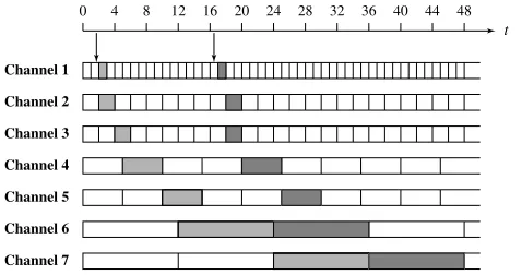
Skyscraper Broadcasting
• A main drawback of the above Pyramid Broadcasting scheme is the need for a large storage space on the client side because the last two segments are typically 75-80% of the movie size.
• Instead of using a geometric series, Skyscraper broadcasting
Channel 1
Channel 2
Channel 3
Channel 4
Channel 5
Channel 6
Channel 7
12 16 20 24 28 32 36 40 44 48
t
0 4 8
Fig. 16.12: Skyscraper broadcasting with seven segments.
• As shown in Fig 16.12, two clients who made a request at time inter-vals (1, 2) and (16, 17), respectively, have their respective transmission schedules. At any given moment, no more than two segments need to be received.
53 Li & DrewcPrentice Hall 2003
Harmonic Broadcasting
• Adopts a different strategy in which the size of all segments remains constant whereas the bandwidth of channeliisBi= b/i, where b is the movie’s playback rate.
• The total bandwidth allocated for delivering the movie is thus
B= K
i=1
b
i =HK·b (16.8)
where K is the total number of segments, andHK =Ki=11i is the Harmonic number ofK.
54 Li & DrewcPrentice Hall 2003
Fundamentals of Multimedia, Chapter 16
Channel 4: Channel 3: Channel 2: Channel 1:
S3,1
S1
S1
S1
S1
S1
S1
S4,1
S2,2
S2,1
S2,2
S2,1
S2,2
S2,1
b/4
b/3
b/2
b
S3,1 S3,2 S3,3
S3,3
S3,2
S4,4
S4,3
S4,2 S4,1 S4,2
Fig. 16.14: Harmonic Broadcasting.
Fundamentals of Multimedia, Chapter 16
• As Fig. 16.14 shows: after requesting the movie, the client will be allowed to download and play the first occurrence of segment S1 from Channel 1. Meanwhile, it will download all
other segments from their respective channels.
• The advantage of Harmonic broadcasting is that the Har-monic number grows slowly with K.
• For example, when K= 30,HK ≈4. Hence, the demand on the total bandwidth (in this case 4·b) is modest.
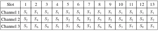
Pagoda Broadcasting
• Harmonic broadcasting uses a large number of low-bandwidth streams, while Pyramid broadcasting schemes use a small number of high-bandwidth streams.
• Harmonic broadcasting generally requires less bandwidths than Pyramid broadcasting. However, it is hard to manage a large number of independent data streams using Harmonic broad-casting.
• Paris, Carter, and Long presented Pagoda Broadcasting, a frequency broadcasting scheme, that tries to combine the advantages of Harmonic and Pyramid schemes.
57 Li & DrewcPrentice Hall 2003
13 Slot
Channel 1 1
Channel 2 2
Channel 3
3 4 5 6 7 8 9 10 11 12
S1 S1 S1 S1 S1 S1 S1 S1 S1 S1 S1 S1 S1
S2 S4 S2 S5 S2 S4 S2 S5 S2 S4 S2 S5 S2
S3 S6 S8 S3 S7 S9 S3 S6 S8 S3 S7 S9 S3
Fig. 16.15: First three channel-segment maps of Pagoda Broadcasting.
• Partitions each video into n fixed-size segments of duration T =L/n, where T is defined as a time slot. Then, it broad-casts these segments at the consumption bandwidth b but with different periods.
58 Li & DrewcPrentice Hall 2003
Fundamentals of Multimedia, Chapter 16
Stream Merging
• More adaptive to dynamic user interactions. It achieves this by dynamically combining multicast sessions.
• Makes the assumption that the client’s receiving bandwidth is higher than the video playback rate.
• The server will deliver a video stream as soon as it receives the request from a client.
• Meanwhile, the client is also given access to a second stream of the same video, which was initiated earlier by another client.
Fundamentals of Multimedia, Chapter 16
0
t B joins A
C joins A
C joins B
C
A
B Bytes
delivered
1 2 3 4 5 6 7 8
• As shown in Fig. 16.16, the “first stream” B starts at time t = 2. The solid line indicates the playback rate, and the dashed line indicates the receiving bandwidth which is twice of the playback rate. The client is allowed to prefetch from an earlier (“second”) stream A which was launched att= 0. Att= 4, the stream B joins A.
• A variation of Stream merging isPiggybacking, in which the playback rate of the streams are slightly and dynamically ad-justed so as to enable merging (piggybacking) of the streams.
61 Li & DrewcPrentice Hall 2003
Buffer Management
• To cope with the VBR and network load fluctuation, buffers are usually employed at both sender and receiver ends:
– APrefetch Bufferis introduced at the client side. If the size of frame
tisd(t), the buffer size isB, and the number of data bytes received so far (at play time for framet) isA(t), then for allt∈1,2, . . . , N, it is required that
t
i=1
d(i)≤A(t)≤ t−1
i=1
d(i) +B. (16.9)
– When A(t) < ti=1d(i), we have inadequate network throughput, and hence buffer underflow (or starvation), whereas when A(t) > t−1
i=1d(i) +B, we have excessive network throughput and buffer over-flow.
– Both are harmful to smooth and continuous playback. In buffer un-derflow there is no available data to play, and in buffer overflow media packets must be dropped.
62 Li & DrewcPrentice Hall 2003
Fundamentals of Multimedia, Chapter 16 Data (bytes)
Available Network Bandwidth I
t (frame #)
Media Data
Available Network Bandwidth II Underflow
Overflow Maximum Buffered Data
B Buffer
(ti=1d(i)) (t−1
i=1d(i) +B)
Fig. 16.17: The data that a client can store in the buffer assists the smooth playback of the media when the media rate exceeds the available network bandwidth
• Fig. 16.17 illustrates the limits imposed by the media play-back (consumption) data rate and the buffered data rate (the transmission rates are the slopes of the curves).
Fundamentals of Multimedia, Chapter 16
An Optimal Plan for Transmission Rates
• It is possible to utilize the prefetch buffer more efficiently for the network given knowledge about the data rate character-istics of the media stored on the server:
– The media server can plan ahead for a transmission rate such that the media can be viewed without interruption and the amount of bandwidth requested for reservation can be minimized.
– Optimal work-ahead smoothing plan: a unique plan that minimize not only peak rate but also the rate vari-ability.
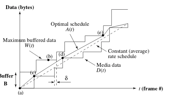
An Optimal Plan for Video and Buffer Size
• Take video as an example (can be extended for general me-dia), it is more practical to approximate the video data rate by considering the total data consumed by the time each I-frame should be displayed.
– The approximation could be made coarser by only considering the total data consumed at the first frame after a scene transition, as-suming the movie data-rate is constant in the same scene.
– Defined(t) to be the size of framet, wheret∈1,2, . . . , N andNis the total number of frames in the video. Similarly, definea(t) to be the amount of data transmitted by the video server during the playback time for frame t (in short call it at time t). Let D(t) be the total data consumed andA(t) be the total data sent at timet. Formally:
D(t) =
t
i=1
d(i) (16.10)
65 Li & DrewcPrentice Hall 2003
A(t) =
t
i=1
a(i) (16.11)
– Let the buffer size be B. Then at any time t the maximum total amount of data that can be received without overflowing the buffer during the time 1..tisW(t) =D(t−1)+B. Now it is easy to state the conditions for a server transmission rate that avoids buffer overflow or underflow:
D(t)≤A(t)≤W(t) (16.12)
– In order to avoid buffer overflow or underflow throughout the video’s duration, Eq.(16.12) has to hold for allt∈1,2, ..., N. DefineS to be the server transmission schedule (or plan), i.e.S=a(1), a(2), ..., a(N).
Sis called afeasible transmission scheduleif for allt,Sobeys Eq. (16.12).
– Figure 16.8 illustrates the bounding curvesD(t) andW(t), and shows that a constant (average) bit-rate transmission plan is not feasible for this video because simply adopting the average bit-rate would cause underflow.
66 Li & DrewcPrentice Hall 2003
Fundamentals of Multimedia, Chapter 16
Data (bytes)
Constant (average) rate schedule Maximum buffered data
W(t)
Optimal schedule
A(t)
(a)
(b) (d)
(c)
(e)
δ
t(frame #)
Media data
D(t)
B Buffer
Fig 16.18: The optimal smoothing plan for a specific video and buffer size. In this case it is not feasible to transmit at the constant (average) data rate
Fundamentals of Multimedia, Chapter 16
16.6 Further Exploration
• Text books:
– Multimedia: Computing, Communications & Applicationsby S. Stein-metz and K. Nahrstedt
– Emerging Multimedia Computer Communication Technologiesby C.H. Wu and J.D. Irwin
– Readings in Multimedia Computing and Networkingby K. Jeffay and H. Zhang
– Video Processing and Communicationsby Y. Wang et al.
• Web sites: −→Link to Further Exploration for Chapter 16.. includ-ing:
– Links to ITU-T recommendations.
– Links to MBone sites.
– Links to RTP, RTSP, SIP Pages.
– Introductions and White Papers on ATM by another client.
– Introductions and White Papers on DVB.
• RFCs(can be found from IETF):
– Criteria for evaluating reliable multicast transport protocols.
– Protocols for real-time transmission of multimedia data (RTP, RTSP, and RSVP).
– Protocols for VoIP (SIP, SDP, and SAP).