Modeling of mechanical energy harvesting system by
utilizing the weight of vehicle as a source of electrical
energy for the portal gate system
Joni Dewanto1, Oegik Soegihardjo2
1,2
Mechanical Engineering Department, Faculty of Industrial Technology, Petra Christian University Jl. Siwalankerto 121-131, Surabaya 60236. Indonesia
Phone: 0062-31-8439040, Fax: 0062-31-8417658 Email: [email protected], [email protected]
Abstract. The gate into residential or vehicle parking area is often equipped with a portal (barrier gate) that is a simple crossbar to block the road. Whenever a vehicle passes through the road, the portal is opened and closed by rotating mechanism of the portal at one end. Portals in public area, are usually not manually operated by officers, but automatic systems powered by an electric motor and become an integral unit with an electric parking ticket printer. In one operating cycle this unit requires small amount of electricity. However for repeatedly large numbers of operating cycle, the accumulation of required energy will also be large.
This study is modeling of a mechanical energy harvesting system utilizes the weight of a vehicle as a source of electrical energy. As the vehicle pass on energy harvesting system, electrical energy is produced to operate the automatic portal unit. Data taken from the specification of a light weight passanger vehicle provides net energi of 592 Nm to the mechanical energy harvesting system. It is more than enough as a source of energy to operate portal (barrier gate) for one operation cycle. The portal needs an energy of 221 Nm for every operation cycle.
Keywords: Mechanical energy harvesting system, portal gate system, vehicle's weight.
.
1. Introduction.
The mechanical energy harvesting system presented in this paper, is one in which the impulsive force of the vehicle's weight is converted into flywheel kinetic energy which is then used to drive the electric generator. The generated electricity will be stored in the battery as a storage of electrical energy for the portal driver motor and parking ticket printer. Energy harvesting system from running vehicles become an alternative energy harvesting system to obtain an electric energy [1]. In this kind of energy harvesting system, the electrical energy obtain from the mechanical motion can be stored on battery. The electrical energy stored on battery can be used even after the vehicle pass the mechanical energy harvesting system.
Flywheel kinetic energy stored in rotating flywheel can be used to rotate an electric generator. The use of flywheel as a device to convert translational movement to a rotary motion is common in mechanical system [2]. The design of the mechanical energy harvesting system is simple and easy to implement compare with more advanced energy harvesting system using piezoelectric power generation [3], [4]
and bistable system [5].
2. Theoretical backgroud
The design of mechanical energy harvesting system presented in this paper consist of two sub system, i.e. mechanical system and electrical system. The mechanical system convert the weight of the vehicle as a source of energy to rotate the flywheel. The electrical system uses the flywheel rotation to drive the electric generator to generates electricity. The mechanical energy harvesting system is appropriate as a source of electrical energy for automatic portal (barrier gate) for shopping malls, business center and also residential area [6], [7], [8].
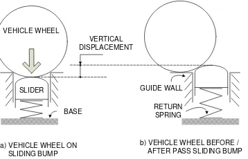
2.1 Mechanical system.
VEHICLE WHEEL
SLIDER
RETURN SPRING GUIDE WALL
BASE
a) VEHICLE WHEEL ON SLIDING BUMP
b) VEHICLE WHEEL BEFORE / AFTER PASS SLIDING BUMP VERTICAL
DISPLACEMENT
Figure 1. Design of the mechanical system.
The amount of energy obtained from the weight of the vehicle is stated in equation (1).
𝑈𝑘 = 𝑚𝑘 𝑔 𝑠𝑘 (1) 𝑚𝑘 is mass of the vehicle, 𝑔 is acceleration of gravity and 𝑠𝑘 is vertical displacement of the sliding bump. To convert the energy obtained from the weight of the
vehicle to an electrical energy, the system is equipped with a mechanical system to rotate the flywheel. The shaft of the flywheel is connected to an electric generator. The system to convert translational movement into rotational motion of the mechanical energy harvesting system is shown in Fig. 2.
1 2
4 5
6 7
8
9
7
7 7
7
6
10
11 SIDE VIEW OF PLANETARY GEAR
+ _
8 3
1. rack 2. pinion 3. rachet wheel
4. pinion shaft 5. planetary gear arm 6. Sun gear
7. planetary gear 8. teta gear 9. Shaft of fix gear
10. fly wheel 11. Electric generator
Figure 2. The system for converting translational into rotational motion.
As the vehicle pass the mechanical energy harvesting system, the wheel of the vehicle (see Fig. 1) will push the sliding bump down. The sliding bump that is connected to rack (1) and pinion (2) as shown in Fig. 2 will also rotate the flywheel which is connected to the shaft of the electric generator. The kinetic energy of the flywheel is expressed in equation (2).
𝐸𝑓=1
2 𝐼 𝜔𝑓2 (2) 𝐼is the mass moment of inertia of the flywheel and 𝜔𝑓 is the angular velocity of the flywheel. The kinematic relationship between vertical displacement of the rack (1) and rotational (angular) displacement of the pinion (2) is stated in equation (3).
𝑠 = 𝑟 𝜃 (3)
r is radius of pinion, s is vertical displacement of the rack and 𝜃 is rotational displacement of the pinion. If
the vertical displacement of the rack, s = 12 cm (for each time the vehicle wheel push the sliding bump down) and the pinion diameter is 6 cm, based on equation (3) the rotational or angular displacement of the pinion can be calculated using equation (4).
𝜃 = 12
3 𝑥 57,30= 229,20 (4)
If time for the vertical displacement of the rack (s = 12 cm) is designed for 0.2 sec, then angular velocity of the pinion (𝜔𝑝) can be calculated using equation (5).
𝜔𝑝=229,20 0,2 𝑠𝑒𝑐=
11460
𝑠𝑒𝑐 = 3,18 𝑟𝑜𝑡𝑎𝑡𝑖𝑜𝑛/𝑠𝑒𝑐 (5)
velocity diagram on the planetary gear pairs is shown in Fig. 3.
5 6 7
9
ωp ωf
Dp
Ds
Vp
Vs
a) PLANETARY GEAR CONFIGURATION
b) VELOCITY DIAGRAM 7
8 8
Figure 3. Kinematics and velocity diagram of planetary gear.
If the diameter of the planetary gear and the sun gear are Dp and Ds respectively, the length of the planetary (R) gear arm is (Dp + Ds) / 2. So that the tangential velocity of the planetary gear shaft (Vp), can be calculated using equation (6).
𝑉𝑝= 𝜔𝑝 (𝐷𝑝+ 𝐷𝑠)/2 (6)
From Figure 3b, it can be determined that the tangential velocity of the sun gear shaft is 2 times faster than the tangential speed of the planetary gear shaft. Because the rotating speed of the sun gear shaft is equal to the rotating speed of the fly wheel (see Fig. 2), it can be calculated by equation (7).
𝜔𝑓= 2𝜔𝑝 (𝐷𝑝+𝐷𝑠)
𝐷𝑠 (7)
By designing Dp equal to 1.4 Ds, then from equation (7) and equation (5), the value of ωf can be obtained that is ωf = 4.8 ωp = 4.8 x 3.18 rotation/second = 15.26 rotation/second. To be able to achieve the rotation required by electric generaotor (50 Hz), the mechanical system is used two pairs of planetary gear arrangements with the same geometry as the first one.
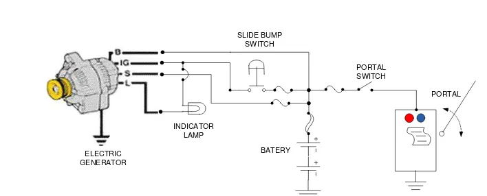
2.2 Electrical system
The electrical system utilizes the fly wheel rotation to rotate the electric generator. The electric generator is equipped with a diode rectifier to produce DC voltage and an ICs regulator to control the amount of current and voltage generated [9]. The diagram of the electrical system of the mechanical energy harvesting system is shown in Fig. 4.
BATERY
PORTAL
INDICATOR LAMP
SLIDE BUMP SWITCH
PORTAL SWITCH
ELECTRIC GENERATOR
Figure 4. The electrical system diagram.
The electric generator has 4 terminals. The B terminal is one for supplying electrical energy produced by the electric generator to the battery. The S terminal is connected to the battery to monitor battery voltage and is used to control the electricity generation system of the electric generator. While the L terminal is used
input signal from the sensor, when the vehicle passes through the portal.
3. Results and discussions.
The results presented are the efficient portal design (low net energy needed to open/close the portal) and the capability of mechanical energy harvesting system to provide energy to operate the portal and parking ticket printer.
3.1 Energy for opening/closing the portal
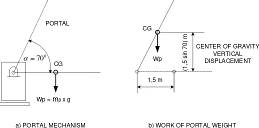
The portal mechanical system consists of a portal (crossbar), a portal drive motor and a power transfer system. The portal is opened and closed by rotating the
portal hinge at one end. The portal or crossbar is made from light weight material such as aluminum profiles, so that the power needed to open and close the portal is small. The portal has a length of 3m [8], and its weight is no more than 8Kg. For this light weight portal, the DC motor is selected as a driver. The power transfer system is used to adjust the output speed and torque, which is needed to move the portal. With the same amount of power, the output torque can be increased proportionally with decreasing output speed. Energy requirements for the mechanical system, can be analyzed from the dynamic of the portal opening/closing system as shown in Fig. 5.
0 70
Wp = mp x g CG
1,5 m
(1
,5
si
n
7
0
) m
CENTER OF GRAVITY VERTICAL DISPLACEMENT CG
a) PORTAL MECHANISM b) WORK OF PORTAL WEIGHT
PORTAL
Wp
Figure 5. Dynamics of portal opening/closing system.
The portal is designed with maximum opening angles of up to 700. In accordance with Fig. 5, the net energy, Up needed to open the portal can be calculated by
equation (8).
𝑈𝑝= 𝑚𝑝 𝑔 𝑠𝑝 (8)
Mass of portal, m is 8 kg, acceleration of gravity, g is 9,8 m/sec2 and sp is vertical displacement of the
portal's center of gravity. With the designed period and opening of the portal, and assuming that the energy to open and close the portal is the same, the total amount of energy needed to open and close the portal can be calculated as follows.
Up tot = 2 x 8 kg x 9,8
𝑚
𝑠𝑒𝑐2x 1,5𝑚 sin 70
𝑈𝑝𝑡𝑜𝑡 = 221 𝑁𝑚
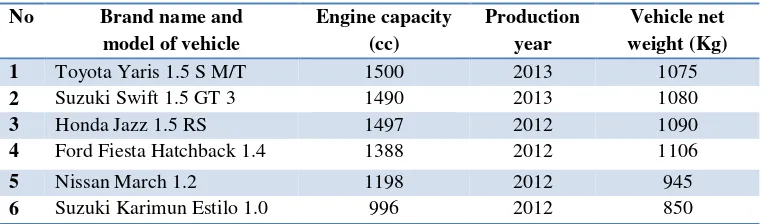
3.2 Energy obtained from the energy harvesting system.
Tabel 1. Specification of the light weight vehicle *
No Brand name and model of vehicle
Engine capacity (cc)
Production year
Vehicle net weight (Kg)
1 Toyota Yaris 1.5 S M/T 1500 2013 1075
2 Suzuki Swift 1.5 GT 3 1490 2013 1080
3 Honda Jazz 1.5 RS 1497 2012 1090
4 Ford Fiesta Hatchback 1.4 1388 2012 1106
5 Nissan March 1.2 1198 2012 945
6 Suzuki Karimun Estilo 1.0 996 2012 850
* Taken from vehicle leaflet
Using data taken from the lightest vehicle
(Suzuki Karimun), and assuming the driver's
weight is 50 Kg, then the energy obtained from
the total vehicle weight (900 Kg) that passing the
portal can be calculated by using equation (1) as
follows:
𝑈
𝑘= 900 𝐾𝑔 𝑥 9,8
𝑠𝑒𝑐
𝑚
2𝑥 0,12 𝑚
Uk
= 1058 Nm
The energy obtained from the lightest vehicle
provides much more energy needed by the portal
gate system.
The real performance of the mechanical
energy harvesting system will be known after the
field testing of the system.
4. Conclusion
Choosing the mechanical efficiency and
electrical efficiency of the mechanical energy
harvesting system for 0.7 and 0.8 respectively, the
net energy obtained is 0.7 x 0.8 x 1058 Nm = 592
Nm. This value is more than twice greater than
the net energy needed to open and close the portal,
which is 221 Nm. For this reason, it can be
concluded that the design of this mechanical
energy harvesting system is capable to provide
the power needed to operate the portal (barrier
gate) and the parking ticket printing.
References.
1.
L. Wang., J. Park., W. Zhou., J. Ban. and L.
Zuo., On-Road Energy Harvesting for
Traffic
Monitoring.,
Final
Report.,
University
Transportation
Research
Center-Region II, City College of New York,
November (2014).
2.
Active Power Inc., Understanding Flywheel
Energy Storage: Does High.Speed Really
Imply a Better Design., White Paper 112,
Austin, Texas, (2008).
3.
W. Hendrowati, H. L. Guntur, and I. N.
Sutantra
.,Design, Modeling and Analysis of
Implementing a Multilayer Piezoelectric
Vibration Energy Harvesting Mechanism in
the Vehicle Suspension
.
, Scientific Research,
Engineering,
4
., p 728-738, (2012).
4.
L.T.E. Nyamayoka, G.A. Adewumi and F.L.
Inambao., Design of a prototype generator
based on piezoelectric power generation for
vibration energy harvesting., Journal of
Energy in Southern Africa,
28
, Number 4., p.
32-40, (2017).
5.
R.L. Harne and K.W. Wang., A review of the
recent
research
on
vibration
energy
harvesting via bistable systems., IOP
Publishing Ltd., Journal of Smart Materials
and Structures.,
22
, (2013).
6.
I. Muslih,
Perancangan Palang Pintu
(Portal) Makanik Elektrik
, Undergraduate
Thesis, University of Muhammadiyah
Malang, (2006).
7.
Palang Parkir (Barrier Gate),
[email protected], (2013).
8.
CAME Access Automation,
www.came-americas.com, (2013).