THE DIRECT GEOREFERENCING APPLICATION AND PERFORMANCE ANALYSIS
OF UAV HELICOPTER IN GCP-FREE AREA
C.F. Lo a , M.L. Tsai b, *, K.W. Chiang c, C.H. Chu d, G.J. Tsai e, C.K. Cheng f, N. El-Sheimy g, H. Ayman h
a GeoSat Informatics Technology Corporation, Tainan, Taiwan - [email protected] b
Dept. of Geomatic, National Cheng Kung University, Tainan, Taiwan - [email protected] c
Dept. of Geomatic, National Cheng Kung University, Tainan, Taiwan - [email protected] d
Dept. of Geomatic, National Cheng Kung University, Tainan, Taiwan - [email protected] e
Dept. of Geomatic, National Cheng Kung University, Tainan, Taiwan - [email protected] f
GeoSat Informatics Technology Corporation, Tainan, Taiwan - [email protected] g
Dept. of Geomatics Engineering, The University of Calgary, Alberta, Canada - [email protected] h
Dept. of Civil Engineering, Purdue University, Indiana, USA - [email protected]
Commission VI, WG VI/4
KEY WORDS: Direct Georeferencing, INS, GNSS, UAV, Helicopter
ABSTRACT:
There are many disasters happened because the weather changes extremely in these years. To facilitate applications such as environment detection or monitoring becomes very important. Therefore, the development of rapid low cost systems for collecting near real-time spatial information is very critical. Rapid spatial information collection has become an emerging trend for remote sensing and mapping applications. This study develops a Direct Georeferencing (DG) based Unmanned Aerial Vehicle (UAV) helicopter photogrammetric platform where an Inertial Navigation System (INS)/Global Navigation Satellite System (GNSS) integrated Positioning and Orientation System (POS) system is implemented to provide the DG capability of the platform. The performance verification indicates that the proposed platform can capture aerial images successfully. A flight test is performed to verify the positioning accuracy in DG mode without using Ground Control Points (GCP). The preliminary results illustrate that horizontal DG positioning accuracies in the x and y axes are around 5 meter with 100 meter flight height. The positioning accuracy in the z axis is less than 10 meter. Such accuracy is good for near real-time disaster relief. The DG ready function of proposed platform guarantees mapping and positioning capability even in GCP free environments, which is very important for rapid urgent response for disaster relief. Generally speaking, the data processing time for the DG module, including POS solution generalization, interpolation, Exterior Orientation Parameters (EOP) generation, and feature point measurements, is less than 1 hour.
* M.L.Tsai - [email protected]
INTRODUCTION
The idea of mobile mapping is basically executed by producing more than one image that includes the same object from different positions, and then the three-dimensional positions of the same object with respect to the mapping frame can be measured (Tao and Li, 2007). Multi-platform and multi-sensor integrated mapping technology has clearly established a trend towards fast geospatial data acquisition. Sensors can be mounted on a variety of platforms, such as satellites, aircraft, helicopters, terrestrial vehicles, water based vessels, and even people. As a result, mapping has become mobile and dynamic. In the words, mobile mapping refers to a means of collecting geospatial data using mapping sensors that are mounted on a mobile platform.
With the number of natural disasters increasing due to climate change, the development of a rapidly deployable and low cost system for collecting near real-time spatial information has become very critical. Therefore, rapid spatial information acquisition capability has become an emerging trend for remote sensing and mapping applications. Airborne remote sensing, more specifically aerial photogrammetry, in its classical form of
film based optical sensors (analogue) has been widely used for high accuracy mapping applications at all scales and rapid spatial information collection for decades. Recently, film based optical sensors (analogue) have been replaced by digital imaging sensors.
Generally speaking, conventional photogrammetric methods rely on huge numbers of Ground Control Points (GCP). Although photogrammetry has adopted digital technology, GCP are generally considered the only source of reliable georeferencing information (Gibson et al., 1992). Recently, Direct Georeferencing (DG) technology has become possible by integrating Inertial Navigation System (INS) and Global Navigation Satellite System (GNSS), making Exterior Orientation Parameters (EOP) available with sufficient accuracy at any instant of time (Gibson et al., 1992). The integration of INS/GNSS improves the georeferencing of photogrammetric data and frees it from operational restrictions. Together with digital data recording and data processing, it allows multi-sensor mapping systems.
Numerous studies have been conducted on the application of Unmanned Aerial Vehicle (UAV) for photogrammetry
applications. A detailed review of UAV photogrammetric applications can be found in reference Eisenbeiss (2004; 2008). Although most schemes apply low cost INS/GNSS integrated systems for flight control, a DG based UAV photogrammetric platform equipped with an INS/GNSS integrated Positioning and Orientation System (POS) that can provide EOP of the camera in a GCP free environment has not been proposed until recently.
TECHNICAL CONFIGURATIONS OF PROPOSED PLATFORM
The proposed multi-rotor UAV platform and its specifications are illustrated in Figure 1. As shown in the figure, the proposed multi-rotor UAV is designed for small range applications. The endurance time is around 15 minute and the max payload is around 1.5 kilogram. Multi-rotor UAV can be operated easily in everywhere. It is suitable for monitoring, investigating, or simple photogrammetric tasks. The multi-rotor UAV can get the status of the area immediately and then we can plan the project by the requirement. It also can help us to renew the photo, construct the three-dimensional model, and panorama for the building or object that we want.
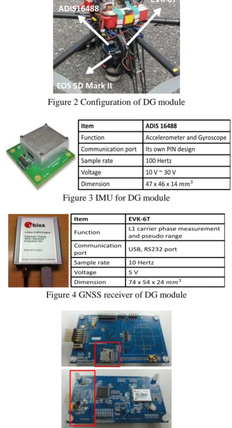
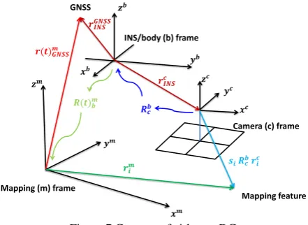
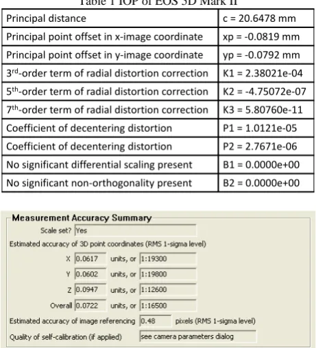
Figure 2 shows the DG module designed in this study for facilitating GCP free photogrammetry applications and INS/GNSS integrated POS aided bundle adjustment photogrammetry. Figure 3 illustrates the Inertial Measurement Unit (IMU) used for DG module, ADIS16488 from Analog Device. This module is chosen due to its compact size and weight. Figure 4 illustrates the specifications of the GNSS receiver, EVK-6T from U-blox, is used in the DG module. This model is chosen because of its L1 carrier phase measurements for Differential GNSS processing (DGNSS), which provides sufficient positioning accuracy. In addition, it supplies Pulse Per Second (PPS) output, which is used to synchronize the time mark used to trigger the camera in the DG module.
To supply the power required for the individual sensors with various power requirements from the battery, a power switch module was designed. Since the camera, a Canon EOS 5D Mark II, has its own power supply, it is not considered in the power supply design. The data storage module is used to record the measurements collected by ADIS16488, EVK-6T, and the synchronized time mark used to trigger the camera. Due to the limitations of the power supply, a PC or notebook based data storage module was ruled out in this study. A simple mechanization that can store measurements transferred through a serial port is thus required. Micro SD card is chosen due to its flexibility, low power consumption, and reliability. Since the camera has its own storage mechanization, it is not included in this module. Figure 5 shows the power switch and data storage module.
Figure 1 Proposed multi-rotor UAV platform
ADIS16488
EVK-6T
EOS 5D Mark II
Figure 2 Configuration of DG module
Item ADIS 16488
Function Accelerometer and Gyroscope
Communication port Its own PIN design
Sample rate 100 Hertz
Voltage 10 V ~ 30 V
Dimension 47 x 46 x 14
Figure 3 IMU for DG module
Item EVK-6T
Function L1 carrier phase measurement
and pseudo range
Communication
port USB, RS232 port
Sample rate 10 Hertz
Voltage 5 V
Dimension 74 x 54 x 24
Figure 4 GNSS receiver of DG module
Figure 5 Power switch and data storage module
Figure 6 shows the proposed new UAV helicopter platform which main rotor is around 1.9 meter and the payload can up to 20 kilogram. The UAV helicopter will also try to carry the proposed DG module as mentioned above including integrated INS/GNSS and digital camera.
Figure 6 Proposed UAV helicopter platform
DATA PROCESSING STRATEGY
Figure 7 illustrates the general concept of the airborne DG. With this implementation, the coordinates of a mapping feature can be obtained directly through measured image coordinates. This procedure works based on the a priori knowledge of various systematic parameters, as shown in the reference (Fraser, 1997).
Mapping (m) frame
INS/body (b) frame GNSS
Camera (c) frame
Mapping feature
Figure 7 Concept of airborne DG
Camera indoor calibration field
For the determination of the boresight angle and lever arm parameters, the EOP must be solved using close range bundle adjustment. However, some errors are introduced during the image measurements due to manufacturing imperfections of cameras. Thus, camera calibration must be performed. The objective of camera calibration is to analyse the Interior Orientation Parameters (IOP), such as lens distortion, focal length, and principle point. These systematic errors can be diminished during the image point measurements. For system calibration and DG measurements, a camera control field and a ground control field were established. Figure 8 shows the indoor calibration field applied in this study to calibrate the IOP of Canon EOS 5D Mark II. Because a digital camera is rather than a traditional camera, which can use the flame frame to rectify systematic error and image coordinate measurement, a bundle method with self-calibration is proposed for determining the IOP of the camera (Tao and Li, 2007). The obtained IOP are applied to enhance the accuracy of EOP estimation and the DG task.
Figure 8 Indoor calibration field
Ground control field
For the determination of calibration parameters, the EOP of each image need be known. They can be calculated by the bundle adjustment using control field. So the control fields are built for calibrating those systems applied in the study. Figure 9 illustrates the distribution of GCP in the control fields which are set up every 100 meters. Those GCP are accurately surveyed by
using RTK (Real Time Kinematic) GNSS and processed with network adjustment software. The standard deviation of GCP is 3 millimeters, and thus they are applied to calibrate the lever arm and boresight angle.
Figure 9 Distribution of GCP in control fields
Boresight angle and Lever arm calibration
In this research, a two-step approach is implemented to conduct the boresight angle and lever arm calibrations. The image acquisition for the calibration process was performed by flying the UAV photogrammetric platform over the ground control field at a flight height of 100 meters. The measurements of the image points were processed. Australis software was then used to calculate the EOP of the images through bundle adjustment. After performing the interpolation of INS/GNSS positioning and orientation parameters at the image exposure time, the differences of the position and the orientation between the EOP acquired by a conventional photogrammetry procedure and interpolated INS/GNSS positioning and orientation parameters were derived for further processing.
In theory, the boresight angle rotation matrices and lever arm derived from each image are the same; however, this is not exactly true in practice. Reasonable values from the calibration can be determined using appropriate weights or the average distribution. After obtaining the calibration parameters, the DG task can be performed without using any GCP. Figure 10 illustrates the DG based photogrammetric process proposed in this study (Chiang et al., 2012).
Figure 10 Proposed DG-ready photogrammetric procedure
Integrated POS data processing
The Tightly Couple (TC) scheme uses a single Kalman Filter (KF) to integrate GNSS and INS measurements, as shown in Figure 11. It depicts that the raw measurements are collected
from the INS and converted into position, velocity, and attitude measurements in the desired coordinate system using the INS mechanization algorithms. In the TC integration, the GNSS pseudo range, delta range, and carrier phase measurements are
Post-mission processing, when compared to real-time filtering, has the advantage of having the data of the whole mission to estimate the trajectory (Shin and El-Sheimy, 2005). This is not possible when using filtering because only part of the data is available at each trajectory point, except the last. When filtering is used in the first step, an optimal smoothing method, such as Rauch-Tung-Striebel (RTS) backward smoother, can be applied (Chiang et al., 2004). It uses the filtered results and their covariances as a first approximation. This approximation is improved by using additional data that was not used in the filtering process. Depending on the type of data used, the improvement obtained by optimal smoothing can be considerable (Gelb, 1974).
For georeferencing process which puts POS stamps on images and measurement process that obtains three-dimensional coordinates of all important features and stores them in Geographic Information System (GIS) database, only post-mission processing can be implemented based on the complexity of those processes (El-Sheimy, 2002). Therefore, most of commercially available DG systems operate in real-time only for data acquisition and conduct most of the data processing and analysis in post-mission mode.
After processing POS and bundle adjustment solutions using measurements acquired over control fields, the calibration and performance verification can be achieved. At first, the position and attitude of POS are converted to [x, y, z] and normalized quaternions form for the further processing, respectively. The smoothed POS solutions are interpolated by linear interpolation at trigger time. The DG procedure is done by using smoothed POS solutions at trigger time and calibration report to obtain IOPs and EOPs of each image. The three-dimension coordinates of interesting points can be solved by conventional
photogrammetric technology such as collinearity equation and intersection. The statistical analysis of UAV performance is estimated by check points and then output the UAV performance report.
RESULTS AND DISCUSSIONS
To validate the impact of flight height on DG performance, a field test was conducted in the summer of 2015. The flight altitudes set for aerial photography was set as 100 meters above ground. The scope of the test zone is 1 kilometers * 1 kilometers, as shown in Figure 12. Owing to the limit of the payload and the impact of side wind affecting the attitude of UAV, the endlap and sidelap were increased to 80% and 40% respectively to insure that the coverage of the stereo pair can overlap completely during the test flight. Although more images have to be processed, it can be guaranteed that the completed coverage of the stereo pair.
Calibration results
Table 1 shows the preliminary IOP results. The error of the camera calibration is acceptable at this stage, and may be improved in future work. Figure 12 shows the accuracy of EOP results from aerial triangulation. The estimated accuracy of image referencing is 0.48 pixels. The influence of the EOP is around 0.01 meters in terms of the three-dimensional positioning accuracy. Figure 13 illustrates trajectory of INS/GNSS integrated POS solutions processed with RTS smoother during the test.
To compare the EOPs results from aerial triangulation and POS trajectory, a two-step approach was implemented to acquire the boresight angle and lever arm of each camera. Table 2 shows the boresight angle and lever arm calibration results.
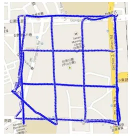
Table 1 IOP of EOS 5D Mark II
Principal distance c = 20.6478 mm
Principal point offset in x-image coordinate xp = -0.0819 mm
Principal point offset in y-image coordinate yp = -0.0792 mm
3rd-order term of radial distortion correction K1 = 2.38021e-04
5th-order term of radial distortion correction K2 = -4.75072e-07
7th-order term of radial distortion correction K3 = 5.80760e-11
Coefficient of decentering distortion P1 = 1.0121e-05
Coefficient of decentering distortion P2 = 2.7671e-06
No significant differential scaling present B1 = 0.0000e+00
No significant non-orthogonality present B2 = 0.0000e+00
Figure 12 EOP results from aerial triangulation
Figure 13 EOP results from POS trajectory
Table 2 Boresight angle/Lever arm calibration result
Verification of DG Capability of Proposed UAV Photogrammetric Platform
The software developed in this study can also perform the DG verification and it utilizes collinearity equation and intersection to calculate the coordinates of check point, as shown in Figure 14. As illustrated in figure, the information including the coordinates of the control points, POS, calibration report and trigger file are imported to the software which calculates the EOP of each image by DG function. Users can perform the image point measurements of those check points appearing in different images. The results of the space intersection of check points are obtained from these images and their coordinates derived through GCP free mode are then compared with known coordinates of them. The reference coordinates of the check points are obtained through the precise control survey with RTK GNSS technology and network adjustment. Therefore, the DG coordinates of those check points are then compared with their reference coordinates.
Figure 14 DG program
Three types of POS solutions, including those obtained using DGNSS and PPP processing strategies, are applied to generate the coordinates of check points through the DG software developed in this study. The solutions are compared with pre-survey known coordinates to validate the performance of the
proposed platform. In order to consider and remove the error of pointing by human, we record the image coordinate of each check points. Therefore, the source of the position errors is only from the POS systems. Table 3 shows a performance summary of the proposed multi-rotor UAV borne DG photogrammetric platform operated in GCP free mode using different processing strategies.
Generally speaking, the positioning accuracies of the proposed multi-rotor UAV borne DG photogrammetric platform operated in GCP free mode using DGNS processing strategies are quite similar. The horizontal absolute DG positioning accuracy is around 5 meter and the vertical absolute DG positioning accuracy is around 10 meter. Because the flight height is lower, there is no significant difference between the positioning accuracies obtained using DGNSS and PPP mode. This finding is consistent with the land test results, where the kinematic positioning accuracy of trajectories generated with DGNSS strategies was less than 1 meter.
Therefore, for rapid disaster assessment applications where ground reference information is not available, the proposed multi-rotor UAV borne DG photogrammetric platform operated in a GCP free environment using PPP and DGNSS mode with L1 carrier phase measurements can provide georeferenced spatial information with sufficient positioning accuracy.
Table 3 Performance summary of proposed multi-rotor UAV platform in GCP free mode
For using UAV helicopter platform, there are some questions of hardware setting that have to be solved. Following shows the results that have finished. Table 4 show the IOP result of camera on UAV helicopter. Figure 15 shows the trajectories about the UAV helicopter in our ground control field. Figure 16 shows the photo mosaic result. The next step will try to calibrate the boresight angle and lever arm, and then verify the DG accuracy.
Table 4 IOP of Sony A7
Principal distance c = 35.2262 mm
Principal point offset in x-image coordinate xp = 0.0510 mm
Principal point offset in y-image coordinate yp = -0.669 mm
3rd-order term of radial distortion correction K1 = 1.30672e-06
5th-order term of radial distortion correction K2 = -4.88983e-09
7th-order term of radial distortion correction K3 = 3.97676e-12
Coefficient of decentering distortion P1 = 2.6448e-06
Coefficient of decentering distortion P2 = -1.0761e-05
No significant differential scaling present B1 = 0.0000e+00
No significant non-orthogonality present B2 = 0.0000e+00
120.377120.378120.379120.38120.381120.382120.383120.384120.385120.386120.387
Figure 15 Trajectories of UAV helicopter
Figure 16 Photo mosaic result
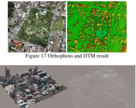
In addition to the results as mention above, there are many applications from multi-rotor and helicopter UAV. Figure 17 and 18 show the different case of result or product from our development UAV.
Figure 17 Orthophoto and DTM result
Figure 18 Three-dimensional model and point cloud result
CONCLUSION
This study developed a multi-rotor and helicopter UAV based DG photogrammetric platform where an INS/GNSS integrated POS system is implemented to provide the DG capability of the platform. Tests verified that the proposed platform can capture aerial images. In order to validate the performance of proposed platform, the field tests with DG module payload were conducted in 2015. The flight altitude for aerial photography was set to 100 meters above ground. The preliminary results shows that the horizontal positioning accuracies in the x and y axes are both around 5 meter, respectively. The positioning accuracy of the z axis is below 10 meter. Such accuracy can be used for near real-time disaster relief.
This study uses GNSS L1 carrier phase raw measurements, which can be applied for DGNSS processing with single frequency carrier phase measurements and used for civilian purposes such as mapping and disaster monitoring. Such
specifications can be applied for the different scenarios to make orthophoto and three-dimensional vector maps. In addition, operators can get the position of each point on a photograph quickly for rescue operations. Therefore, the proposed platform is relatively safe and inexpensive for collecting critical spatial information for urgent response such as disaster relief and assessment applications where GCP are not available. Generally speaking, the data processing time for the DG module, including POS solution generalization, interpolation, EOP generation, and feature point measurements, is less than 1 hour.
In the future, we will try to solve the hardware question from UAV helicopter. Then, the boresight angle/lever arm will be calibrated and doing the DG verification. In addition, the studies are conducted to implement a static ground calibration procedure to improve the DG positioning accuracy of the proposed platform. A one-step approach will be developed to guarantee accurate boresight angle and lever arm calibrations and a cluster based tightly coupled integrated scheme will be investigated to guarantee the stability of POS solutions for practical GCP-free applications.
ACKNOWLEDGMENTS
The authors acknowledge the financial support by the National Science Council of Taiwan (NSC 100-2119-M-006-023). Dr. Cheng-Feng Lo with his company and AVIX Technology are acknowledged for assisting the development of the UAV platform as well as their assistance in conducting the test flight.
REFERENCES
Chiang, K.W., Noureldin, A., and El-Sheimy, N., 2004, A New Weight Updating Method For INS/GPS Integration Architectures Based On Neural Networks, Measurement Science and Technology, Volume 15, Issue 10, Page 2053-2061. Chiang, K.W., Tsai, M.L., and Chu, C.H., 2012, The Development Of An UAV Borne Direct Georeferenced Photogrammetric Platform For Ground Control Point Free Applications, Sensors, Volume 12, Number 7, Page 9161-9180. Eisenbeiss, H., 2004, A Mini Unmanned Aerial Vehicle (UAV): System Overview And Image Acquisition, International Workshop on Processing and Visualization using High Resolution Imagery, The International Archives of Photogrammetry, Remote Sensing and Spatial Information Sciences, Volume XXXVI-5/W1.
Eisenbeiss, H., 2008, The Autonomous Mini Helicopter: A Powerful Platform For Mobile Mapping, The International Archives of the Photogrammetry, Remote Sensing and Spatial Information Sciences, Volume XXXVII, Part B1, Page 977-983. El-Sheimy, N., 2002, Introduction To Inertial Navigation, Geomatics Department, University of Calgary, Alberta, Canada. Fraser, C.S., 1997, Digital Camera Self-Calibration, ISPRS Journal of Photogrammetry and Remote Sensing, Volume 52, Issue 4, Page 149-159.
Gelb, A., 1974, Applied Optimal Estimation, Massachusetts Institute of Technology, Cambridge, Massachusetts.
Gibson, J.R., Schwarz, K.P., Wei, M., and Cannon, M.E., 1992, GPS-INS Data Integration For Remote Sensing, Position Location and Navigation Symposium, IEEE PLANS '92., IEEE , Page 480.
Scherzinger, B.M., 2000, Precise Robust Positioning With Inertial/GPS RTK, Proceeding of ION GPS, Salt Lake City, Utah, United States, Page 155-162.
Shin, E.H., and El-Sheimy, N., 2005, Navigation Kalman Filter Design For Pipeline Pigging, Journal of Navigation, Volume58, Issue 2, Page 283-295.
Tao, C.V., and Li, J., 2007, Advance In Mobile Mapping Technology, International Society for Photogrammetry and Remote Sensing (ISPRS) Book Series, Taylor and Francis, London, UK.