Mechanical Properties of Clayey Sand Treated with
Cement-Rubbershreds
Chan, C.M.1
Abstract: Residual soils of clayey sand composition can potentially be treated to construct a 2-layer pavement system. Using cement as the primary binder and recycled rubbershreds (<2 mm thick, 0.425 mm - 12 mm in length) as filler material, the improved ground can serve as a reliable road foundation, overlain with a surface capping layer. In order to determine the performance of this treated foundation layer, the relevant mechanical properties were examined using suitable laboratory tests, i.e. compaction, unconfined compressive strength and bender element tests. From the test results, it can be concluded that a mixture of cement and recycled rubbershreds effectively enhanced the mechanical properties of the soil. The cement dosage was kept at a minimum to bind the soil and rubbershreds for long term durability, while the rubbershreds served as a flexible filler material, without compromising the targeted strength and compressibility.
Keywords: Cement, rubbershreds, residual soil, pavement.
Introduction
Residual soils commonly distributed in tropical countries are well known as good backfill materials. However, the high fine contents mean that the soil has characteristics more like a cohesive material than a granular one. Typical features, such, as low strength and high compressibility are arguably the two most problematic characteristics of the material. Therefore, many of the unpaved roads built on these soils often end up damaged with the need for regular repair and maintenance, a condition made worse by the high rainfall intensity as well as monsoon seasons, not to mention shoddy workmanship. On the other hand, by stabilizing in situ soils to form road foundations and capping the surface with a thin layer of cemented crushed rock (i.e. 2-layer road system), savings of materials, costs and labor are possible while providing a satisfactory access road for
the local community. Considering today‟s severe
depletion of raw materials and alarming deteriora-tion of environmental quality, it is timely to explore alternative construction methods and materials to fulfill the needs of the present without compromising those of future generation.
1 Research Centre for Soft Soils, Faculty of Civil and Environmental Engineering, Universiti Tun Hussein Onn Malaysia, 86400 Parit Raja, Batu Pahat, Johor, MALAYSIA.
Email: [email protected]; [email protected]
Note: Discussion is expected before June, 1st 2012, and will be published in the “Civil Engineering Dimension” volume 14, number 2, September 2012.
Received 09 June 2011; revised 26 October 2011; accepted 10 November 2011.
Past researchers [1-3] have successfully demon-strated the incorporation of granulated rubber in soil stabilisation. On the other hand, the reuse of recycled wastes, like rubbershreds processed from used tires, inadvertently raised concerns over potential conta-mination and pollution, both of which could result in severe or irreversible environmental impact [4]. Such valid claims of possible detrimental effects on the environment were examined by Tatlisoz et al. [5], where an extensive literature survey on the environ-mental suitability of tire chips was carried out by the authors. It was revealed that despite the worst case scenarios of actual field conditions simulated in laboratory models, no significant threats could be identified from the relevant leaching tests.
Rubber is well recognized for possessing desirable qualities like durability, strength, resiliency and high frictional resistance [6]. These inherent properties make rubber a suitable inclusion in civil engineering works for enhanced performance. As reported by Hazarika et al. [7], recycled rubberchips and rubber-shreds are not dissimilar to the ubiquitous geosyn-thetics used in a wide range of civil engineering applications, including drainage, leachate control, reinforcement, bearing capacity improvement, erosion control, thermal insulation, noise barriers and of course, soil stabilisation. Indeed, the reuse of these otherwise waste materials does not only help in preserving the environmental well-being, but also taking a step closer to sustainable construction and development at significant cost benefits.
road in a local oil palm plantation. The laboratory work included characterization of the soil, bender element test to assess the improved stiffness, as well as the unconfined compression test.
Materials and Methods
As the field application was intended for a treated road foundation of no more than 500 mm thick, disturbed samples were collected from within the depth for characterization purposes. The soil was found to be uniform for the depth, and the relevant properties are given in Table 1. The site was overlain with debris from past relaying and maintenance exercises. Hence the top 50 mm was initially scraped and removed to avoid such impurities in the retrieved soil samples (Figure 1).
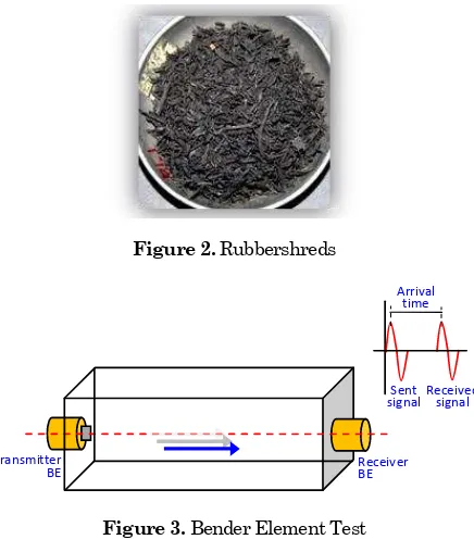
The rubbershreds (RS) used in this study were provided by a used tire processing plant. The shreds were within the size of 0.425 mm - 12 mm in length, and the thickness was generally less than 2 mm (Figure 2). Referring to the classification system for processed rubber in ASTM D6270-98 [8], the
rubber-shreds were categorized as „granulated rubber‟.
Ordinary Portland cement (C) was used as the binder of the soil and rubbershreds.
The test specimens were prepared by first mixing the soil, cement and rubbershreds at pre-determined quantities in a kitchen mixer. Pair of specimens with a range of water, cement and rubbershred contents were examined to identify the optimum mix ratios for the targeted performance (Table 2). The mixture was next transferred to a detachable steel mould (internal dimensions 100 mm x 50 mm x 30 mm), and compacted with a hydraulic press up to 20 kPa. Upon demoulding, the specimens were wrapped in cling film and stored in a humid chamber for curing.
Figure 1. The Proposed Trial Road Site-Overlain with Debris from Past Repair Works
Figure 2. Rubbershreds
Transmitter
BE Receiver BE
Arrival time
Sent signal Received signal
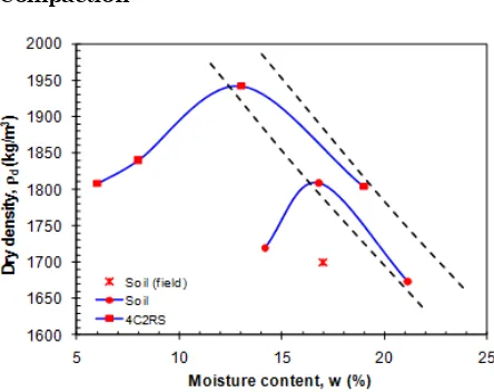
Figure 3. Bender Element Test
Table 1. Properties of the Soil
Original soil Specific gravity Liquid limit, wL Plastic limit, wP Shrinkage limit, wS D10
D30 D50 D60
Mixed soil
2R (2 % rubbershreds) 4C (4 % cement) 4C 2R (4 % cement and 2 % rubbershreds)
SC: clayey sand 2.73
48.25 % 23.68 % 8.21 % 0.07 mm 0.22 mm 0.35 mm 0.48 mm
*Shrinkage limit, wS 9.29 %
7.86 % 6.43 %
*The stabilized material displayed reduced shrinkage: an advantage for field applications.
Then, bender element tests were conducted with the GDS BE (bender element) Test System, where P- (compression) and S- (shear or transverse) waves were sent through the specimens (Figure 3). By identifying the tip-to-tip travel distance and time of the waves respectively, the wave velocities (vp and vs) were simply derived by dividing distance with time. More details on bender element tests and the wave arrival time determination can be referred to in Chan [9]. Assuming the specimen to be an elastic, isotropic and homogeneous medium, the small strain stiffnesses of the material can be obtained as follows:
Bulk modulus, K = vp2 (1)
In which, vp is the P-wave velocity, vs, the S-wave
velocity, andthe bulk density.
Table 2. Mix Ratios of the Test Specimens (a pair each)
Specimen Cement, C
(%)
Rubbershreds, RS (%)
Soil 0 0
4C 4 0
2RS 0 2
3RS 0 3
4RS 0 4
4C2RS 4 2
Note: C and RS percentages were calculated based on dry weight of soil.
A conventional unconfined compressive strength test apparatus was used to evaluate the strength of the specimens, with reference to the procedure pre-scribed in BS 1377 [10]. The same specimens used in the non-destructive bender element tests were subjected to the compression tests, eliminating any discrepancies that might arise from non-uniformity of the test specimens prepared.
Results, Analysis and Discussions
Compaction
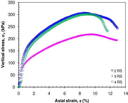
Figure 4. Relationship Between Density and Water Content of the Soil
Serving as a road foundation, the density of the treated soil layer is naturally of much concern. The compaction curve of the soil is shown in Figure 4, together with the field and remolded densities. The natural water content, w, of the soil was 17%, corresponding to a dry density, d, of about 1700 kg/m3. The compaction curve derived from standard procedure gave a maximum d of 1800 kg/m3 at approximately the same water content, suggesting an under-compacted soil layer on site. Probably due to the sandy nature of the soil, the maximum density was achieved with remnants of approximately 5% of air voids in the compacted soil mass.
The entrapped air within the compacted soil mass was undesirable for long term performance of the road foundation, as it can permit water infiltration and eventual loosening of the soil structure with increased permeability. By mixing the soil with 4% cement and 2% rubbershreds, there remained approximately 5% air voids in the soil matrix at optimum water content. Note that this is not much different from the compacted soil only specimen, indicating the impossibility of total air pockets elimination even with induced cementation. Besides, the corresponding increase in density of the treated soil was admittedly marginal, i.e. about 8% (Figure 4). This minor change in density can be attributed to the small dosage of cement added in the mixture, as well as the low density of rubbershreds.
It has been observed too, that additional 2.5-3.0% water was required to form the treated soil. This was inevitable for a couple of reasons: (1) to lubricate the additional surface area of the rubbershreds; (2) to provide water for the cement hydration process, which binds the soil particles and rubbershreds to form a strengthened matrix. It is worth noting here, that based on a preliminary soaking test conducted on the rubbershreds, the material was not found to have an affinity towards water, hence ruling out the need for additional water to accommodate absorption.
Looking at the compaction curve of 4C2RS, it is intuitive to target the maximum d compacted at optimum water content, wopt, in field applications. However wopt= 13% is lower than the soil‟s natural water content of 17%, suggesting prior partial drying of the in situ soil if these values are to be adopted and achieved on site. The tendency of the soil-cement-rubbershreds mixture to form non-uniform lumps under a low moisture environment was also noticed during the compaction test. As homogeneity of the mixture can hardly be expected with deprived water, especially with the onset of cement hydration, the increased density recorded can be misleading for practical purposes.
Effects of Cement and Rubbershreds on Strength
The plots indicate that too much of rubbershreds added to the clay can significantly reduce the strength, i.e. 4RS specimen. More importantly, con-sidering the similar strength values of specimens 2RS and 4RS, the rubbershred dosage was fixed at 2% for subsequent mixes, for the apparent reason of avoiding wastage. The benefits towards strength enhancement with rubbershreds addition is not unlike that of fibre inclusion, such as reported by Muntohar [11] who examined the strength of a clay soil stabilized with lime–rice husk ash–plastic fiber. It was suggested that the frictional contact between fibers and soil particles contributed to the strength increase.
In Figure 6, the stress-strain plots of various specimens were included. By comparing the soil only
specimen (labeled as „Soil‟) with that of 2RS, the
rubber component clearly introduced ductility to the soil. This was accompanied by an approximately 50% of strength reduction too. However, when 4% of cement was mixed with the soil (specimen 4C), the strength was dramatically raised by almost 2.5 times. When 2% rubbershreds was added to the same mixture (specimen 4C2RS), a slight drop in the strength can be observed. This can be attributed to the flexibility of the rubbershreds. It should be noted that in spite of the slight drop in the unconfined compressive strength, qu, the stiffness of the composite material remained largely unchanged. It can be deduced that the rubbershreds acted as a filler material, consequently reducing the amount of cement required to attain similar strengths without rubbershreds.
Figure 7 shows the specimens after compression tests. Comparing the first 2 photos, it can be seen that cement effectively hardened the soil, where the cemented specimen displayed a distinct failure plane during compression. On the other hand, a brittle failure mode was observed with the addition of rubbershreds alone to the soil. A combination of cement and rubbershreds resulted in a compromised failure mode: hardened, but with additional tensile resistance against brittle failure. Being slightly expanded post-compression, the soil-cement-rubber-shreds specimen is notably less distorted compared
to the soil only specimen (compare „Soil‟ and „4C2RS‟
in Figure 7).
Referring to earlier discussions on the compacted densities of the mixture, further insights on the improved properties of the mixture can be acquired. The unchanged density of the soil-cement-rubber-shreds mixture, compared to the compacted soil
alone (Figure 4), was not reflective of the mixture‟s
markedly improved strength (Figure 6). This can be explained by the induced bonding of cement added to
the mixture. In application, the relatively unchanged density indicates a potential advantage in terms of subsidence control, due to self-weight of the treated soil layer.
Figure 5. Unconfined Compression Test Results of Soil-Rubbershreds Specimens
Effect of Mixing Water Content on Stiffness
Shown as P-wave or S-wave velocity (vp and vs respectively), the measured values over a period of 8 days for specimens with 4% cement and 2% rubbershred additions are given in Figure 8. The mixing water content (w) was varied between 6-13%, based on dry weight of the soil. Albeit the slight scatter in both plots, it can be clearly seen that stiffness of the specimens increased markedly within a day of mixing, and remained fairly unchanged for the rest of the curing period. Also, the variation in mixing water content did not appear to significantly affect the improved stiffness.
These observations are important for field appli-cations, particularly (1) to determine the necessary resting period before the overlying or capping layer can be placed; (2) to identify the effect of surface
Figure 8(a). P-Wave Velocity (vp) of the Various Specimens
0
Figure 8(b). S-Wave Velocity (vs) of the Various Specimens
0 velocity data points grouped according to the age of the specimens. vp is generally reported to be 1.5-2.0 times that of vs. By taking the average of the upper and lower limits for the data, it was established that vp is approximately 1.4 times of vs. The correlation is useful should only P-wave measurement is available, where vs could be readily estimated. Of course, it is puzzling that some data points should fall below that of the line of equality (i.e. vp = vs). It is postulated that a plausible explanation is the poor contact between the bender element transducers and the specimen during measurement. As the wave veloci-ties depend very much on the quality of signals captured for interpretation, which in turn depends on the good contact of the transducers and the material tested (among other factors influencing wave propagation through a confined medium), it was perceived to be the most probable cause of the discrepancy observed.
Conclusions
While the soil-cement-rubbershreds mixture was shown to produce greater densities with lower water contents in the compaction test, it is deemed unsuitable for site applications, for the range was below that of the natural water content of the in situ soil.
For field application, it is recommended that cement be introduced in liquid form, which corresponds to an additional 3% water, so as to facilitate more effective mixing and compaction of the materials.
rigidity and brittleness caused by cementation. This is considered a favorable characteristic for the proposed road foundation: enhanced durabi-lity, comfort and trafficability.
Based on the stiffness check with bender elements, no more than 24 hours is necessary as the resting period for the treated soil. However care should be taken to prevent moisture loss during the period, such as by covering the treated surface layer from exposure to the elements. As in concrete and reports of premature drying of stabilized soils, shrinkage can occur, and the resulting strengths can be compromised. It is worth noting that subsequent field trial showed
that „crusting‟ (formation of a thin solidified layer) can take place, leaving the treated layer suscep-tible to surface damage.
Acknowledgment
The study was financially supported by the
Univer-sity‟s Research and Innovation Centre. Special thanks to SS Ch‟ng, BL Tang, MH Ho and LP Low
from RECESS for their active and invaluable part-icipation in this study.
References
1. Lee, J. H., Salgado, R., Bernal, A., and Lovell, C. W., Shredded Tires and Rubber-Sand as Lightweight Backfill. J. Geotechnical & Geoenv. Engrg., 125(2), 1999, pp. 132-141.
2. Bosscher, P.J., Edil, T.B., and Kuraoka, S., Design of Highway Embankments using Tire Chips. J. Geotechnical & Geoenv. Engrg., 123 (4), 1997, pp. 295-304.
3. Tweedie, J.J., Humphrey, D.N., and Sandford, T.C., Full Scale Field Trials of Tire Chips as Lightweight Retaining Wall Backfill, At-rest
Conditions. Transportation Research Record, Transprotation Research Board, Washington, D.C., USA, 1998.
4. Edil, T. and Benson, C., Geotechnics of Industrial Byproducts, Recycled Materials in Geotechnical Applications, GSP No. 79, ASCE, 1998, pp. 1-18.
5. Tatlisoz, N., Edil, T., Benson, C., Park, J., and Kim, J., Review of Environmental Suitability of Scrap Tires. Environmental Geotechnics Report 96-7, Department of Civil and Environmental Engineering, University of Wisconsin, USA, 1996.
6. Zornberg, J.G., Cabral, A.R. and Viratjandr, C., Responses of Excess Pore Water Pressure in Soft Marine Clay around a Soil–cement Column.
Canadian Geotechnical J., 41(2), 2004, pp. 227-241.
7. Hazarika, H., Hyodo, M., and Yasuhara, K., Investigation of Tire Chips-sand Mixtures as Preventive Measure against Liquefaction. Geo-Shanghai International Conference, Shanghai, China, 2010.
8. American Society for Testing and Materials, ASTM D6270-98: Standard Practice for Use of Scrap Tires in Civil Engineering Applications, 2004.
9. Chan, C.M.,Shear Wave Velocity Measurement in Stabilized Soil Specimens: Arrival Time Determination. International Symposium on Deep Mixing and Admixture Stabilisation (OKINAWA 2009), Okinawa, Japan, 2009.
10.British Standards Institution (BSI), BS1377:
British Standard Methods of Test for Soils for Civil Engineering Purposes, 1990.