Compressive Strength Prediction of Square Concrete Columns
Retrofitted with External Steel Collars
Pudjisuryadi, P.1 and Tavio2
Abstract: Transverse confining stress in concrete members, commonly provided by transverse reinforcement, has been recognized to enhance strength and ductility. Nowadays, the confining method has been further developed to external confinement approach. This type of confinement can be used for retrofitting existing concrete columns. Many external confining techniques have been proven to be successful in retrofitting circular columns. However, for square or rectangular columns, providing effective confining stress by external retrofitting method is not a simple task
due to high stress concentration at column’s corners. This paper proposes an analytical model to
predict the peak strength of square concrete columns confined by external steel collars. Comparison with the experimental results showed that the model can predict the peak strength reasonably well. However, it should be noted that relatively larger amount of steel is needed to achieve comparable column strength enhancement when it is compared with those of conventional internally-confined columns.
Keywords: Analytical model, external confinement, peak strength, square concrete columns.
Introduction
Transverse confining stress in concrete columns has been known to enhance the strength and ductility [1-10]. Commonly, confining stress in columns is provided by conventional transverse reinforcement (stirrups). Up to present, many experimental and analytical studies have been conducted to investigate the effects of confinement [1-19]. These studies covered circular and square column sections. The loadings of the specimens included axial and combined axial and bending in monotonic and cyclic patterns. In the case of cyclic loading, only the envelope curves are predicted by analytical models. It was concluded that the variables affecting the behavior of confined concrete were the plain concrete compressive strength, the volumetric ratio of lateral steel to concrete core, the yield strength of transverse reinforcement, the ratio of longitudinal steel around the core perimeter, the resulting tie configuration, and the tie spacing. General agreements on the differences between the improved stress-strain relationship of confined concrete and that of uncon-fined concrete are the increase of compressive strength, the flatter post-peak descending branch of the curve, and the increase of ultimate compressive strain (increase of ductility).
1 Ph.D. Candidate, Department of Civil Engineering, Sepuluh Nopember Institute of Technology (ITS), Surabaya, INDONESIA and Department of Civil Engineering, Petra Christian University, Surabaya, INDONESIA. Email: [email protected]
2 Department of Civil Engineering, Sepuluh Nopember Institute of
Technology (ITS), Surabaya, INDONESIA
Note: Discussion is expected before June, 1st 2013, and will be
published in the “Civil Engineering Dimension” volume 15, number
2, September 2013.
Received 16 November 2012; revised 15 January 2013; accepted 07 February 20113.
This typical improved stress-strain relationship of confined concrete is shown in Figure 1. In which,
f
t,co
f
,
f
cc
,
t
co,
cc,
cu,
sp,E
c, andE
sec are the tensile strength of concrete, the compressive strength of unconfined concrete, the compressive strength of confined concrete, the tensile rupture strain of concrete, the concrete strains corresponding to peak strength of unconfined concrete, the concrete strains corresponding to peak strength of confined concrete, the ultimate compressive strain of confined concrete, the strain at which the concrete cover is considered completely spalled, the modulus of elas-ticity of concrete, and the secant modulus of confined concrete at peak stress, respectively.Recently, studies on confined columns have been further developed to externally applied confinement [11-14]. High demand for columns retrofits is one of the main reasons why such approach is essential to be developed. Many techniques have been proven by experiments to be successful in retrofitting circular columns [11-14]. However, for square and rectangular columns, providing effective confining stress by external retrofit is not an easy task. Some experimental and only a few analytical studies are found to address this problem [15-17]. Similar to conventional internal confinement, the non-uniform stress distribution (Figure 2) is also experienced by the square sections confined by external steel collars (Figure 3). Beside this similar condition, external confinement approach will further increase the complexity of the column behavior. The failure mechanism and contact behavior between concrete and external confinement elements can be different to those of conventional stirrups. In this paper, an analytical model for predicting the axial stress-strain curve of square columns confined by external steel collars is proposed.
Figure 2. Non-uniform Confining Stress of Square Column Confined by Rectangular Stirrups [4]
Figure 3. Non-uniform Confining Stress of Square Column Confined by External Steel Collars
Proposed Analytical Model
The proposed model for predicting the stress-strain relationship combines Tabsh [18], Mander [2], and Hoshikusuma [19] models. The analytical model of confining stress of external steel collars through combined bending and axial actions is adopted from Xiao and Wu [15]. The development as well as necessary modifications are further described in the following sections.
Development of the Model
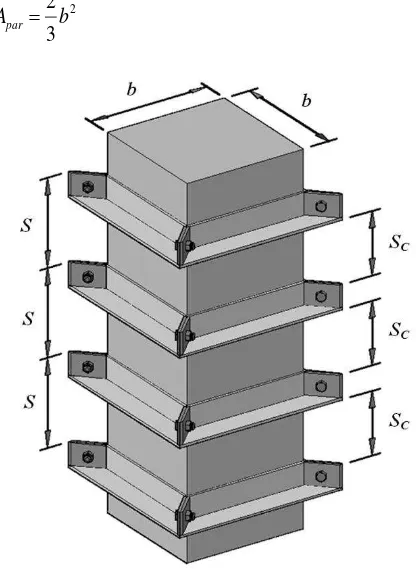
Consider a concrete column, which is externally retrofitted by steel collars (steel L-shaped sections), as illustrated in Figure 4. The notations b, S, and Sc are the dimension of the square column, the spacing of steel collar elements, and the clear spacing of steel collar elements, respectively.
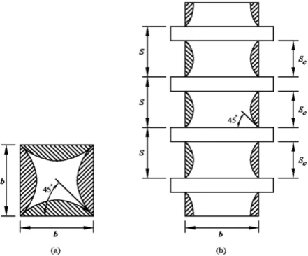
In a column cross section through the confinement element, the confining stress is not uniform (Figure 3). This condition causes some ineffectively confined regions across the square section. In Figure 5(a), the arching action is assumed to act in the form of second-degree parabolas with an initial tangent slope of 45 at the corners (results in an ineffectual area of b2/6 for each parabola [2,4]). To take into account all parabolas on each side of the column, an expression of the ineffectively confined area (Apar) can
then be calculated as given in Equation 1.
2
2
3
par
A
b
(1)The ineffectively confined parabolic regions are also assumed vertically between adjacent confinement elements as seen in Figure 4(b). In consideration of both ineffective regions in horizontal and vertical directions, and average effectively confined cross sectional area, Ae, can be adopted from Mander et al.
[2] as given in Equation 2.
2
1
1
2
par c e c cA
S
A
A
A
b
(2)where Ac is the core area, which is the gross section
area of the column (b2) in the case of externally
confined columns. Further, a confinement effect-tiveness factor (ke) is introduced as expressed in
Equation 3. e e cc
A
k
A
(3)where Acc is the net core area of the columns (Ac
minus the area of longitudinal bars, if any). To take into account the actual non-uniform lateral confining pressure, this factor is used to modify the equivalent uniform confining pressure (
f
, which will be explained in the next section) into the effective equivalent uniform confining pressure (see Figure 6),e
f
, as given in Equation 4.
k
f
f
e
e (4)With the effective equivalent uniform confining pres-sure determined, the peak strength can then be cal-culated by Tabsh models, as provided in Equation 5.
0 0 0 2 94 7 1 254 2 254 1 c e c e c cc f f f f . . . f f
(5)
where
f
cc
is the compressive strength of confinedconcrete (MPa) and
f
c
0 is the compressive strength of unconfined concrete (MPa).Figure 5. Parabolic-shaped Ineffectively Confined Region at: (a) Cross Section; and (b) Along the Height of the Column
Figure 6. Effective Equivalent Uniform Confining Stress
Confining Pressure Provided by Steel Collars (
f
)Externally confined square concrete columns tend to have more effective confinement at the corners due to stiffer confining elements. This fact is also observed in conventionally confined concrete using internal transverse reinforcement. According to Xiao and Wu [15], external steel collars provide the confining pressure through combined bending and axial mechanism. This is different from the assumption for transverse reinforcement which only depends on axial action because of the relatively small bending stiffness. First, consider a bulged externally retrofitted concrete column under axial load in Figure 7(a). The steel collars are assumed to deform in such a way to maintain the compatibility of outward expansion of the concrete. This deformation is logically larger at the mid-sides than at the corners. The actual non-uniformly generated confining pressure is simplified with the assumption of uniformly generated confining pressure. The steel collars are assumed to fail in combined axial and bending mechanism. It is assumed that the steel collars are fixed at the
column’s corners. Since the fixed-end bending moments are very high (twice of those at the mid-length), the yielding of the collar due to flexure is assumed to occur only at its corners. At this stage, the confining action of the collar becomes less effective due to the decrease in stiffness at its corners. This condition may lead to a large lateral expansion of collars and thus, concrete failure. The equilibrium of forces along cross sectional plane can be seen in Figure 7(b) (only a quarter of the model is analyzed due to double symmetric condition).
Using the equilibrium of the forces, the axial (p) and bending moment (m) developed in the steel collars can be expressed as a function of equivalent uniform confining pressure (
f
), dimension of column (b), and spacing of steel collars (S), as given in Equations 6 and 7.S b f p 2 (6) 2 12 b
Figure 7. Confining Pressure through Combined Bending and Axial Mechanism: (a) Bulged Steel Collars Due to Lateral Expansion of Axially Loaded Concrete Column; and (b) Equilibrium of Forces Analyzed at a Quarter of the Cross Section
With nominal axial and bending capacities (pn and mn) of steel collars given, and adopting criteria of
combined axial and bending failure of steel (Equation 8) in Indonesian structural steel code [20],
f
can be determined. In calculating nominal capacity, the reduction factors () in Equation 8, shall be taken as 1.0.0 1 for
1 9
8
. p p m
m p
p
n n
n
(8a)
0
1
for
1
2
p
.
p
m
m
p
p
n n
n
(8b)Comparison with the Experimental Results
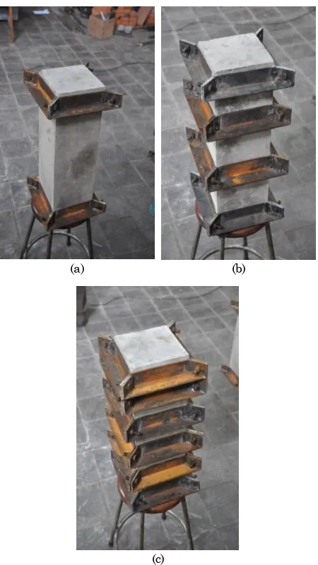
A set of experiment was conducted to verify the proposed analytical model. Three plain concrete column specimens were externally retrofitted by three different configurations of steel L-shaped collars as shown in Figure 8. Description of each column and the steel collars can be seen in Table 1. The concrete cylinder strength,
f
c
from the sameconcrete mix as the column specimens is 24.6 MPa (with standard deviation of 1.17 MPa). All the specimens were tested under static concentric compressive loading to observe their peak strengths. These results, as well as the corresponding analytical predictions, are listed in Table 2. In order to observe the effect of confinement, it is necessary to normalize the concrete strength with respect to their uncon-fined strength (
f
c
0), taken as0
.
85
f
c
(equals to 20.9 MPa), which is commonly used to relate in-place strength to the standard cylinder strength [16]. The enhancements of the strengths are then presented relative to the in-place strength. The specimens observed strength indicated good pattern, with the most confined specimen (Column C) reached the highest strength of 26.8 MPa. This means that the external steel collar confinement with volumetricratio of 25.7 percent achieved compressive strength enhancement approximately 28.42 percent. Columns A (the least confined specimen) and B achieved the strength enhancement of approximately 12.73 and 18.23 percent, respectively. These results were reasonably well predicted by the proposed analytical model. The model slightly underestimated the peak strength of Columns A and B with deviations of less than one percent and only overestimated Column C with a deviation of 1.86 percent.
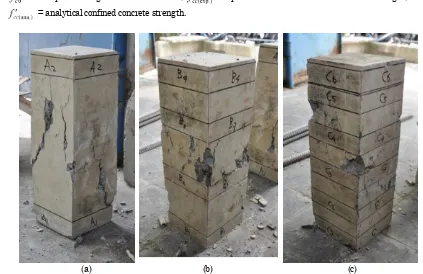
Figure 9 describes a view of the damage pattern of each column. It can be seen in the figure that the application of steel collars can effectively reduce the column damage. The locations of removed steel collars after testing were marked with the parallel lines and texts in between. Damages are seen more severe in regions outside the steel collar locations. This condition is expected since the confinements in these regions are not as effective as in the collared regions (as previously assumed in Figure 5).
(a) (b)
(c)
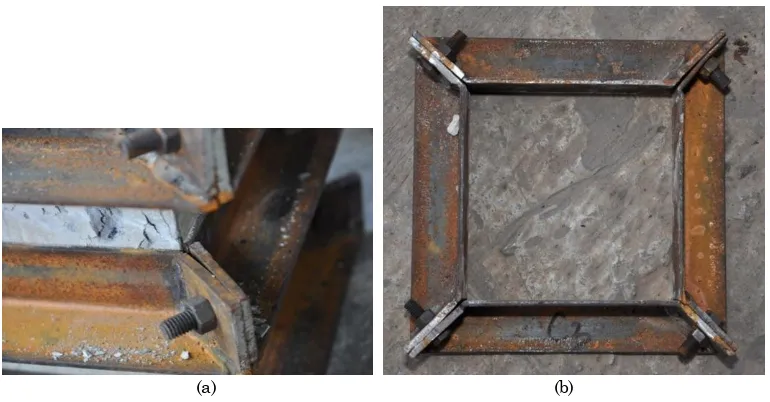
Figure 10 illustrates the typical deformation of the steel collars. It can be seen in Figure 10(a) that the steel collar suffered plastic deformations at its corner. In Figure 10(b), it can be observed that the mid-lengths of steel collar did not experience any plastic deformations. As expected, the worst and least steel collar damages were observed at the mid-height (test) region and both ends of the columns, respectively. These evidences indicated that at
mid-height regions of the columns with most damages, the steel collars performed as expected by the proposed analytical model.
In the experiment, it should also be noted that the corner bolts were fastened with the minimum forces so that they did not generate significant pretension forces. No grouting material is used. The study is a preliminary phase of an on-going research project.
Table 1. Data of Column Specimens
Specimen Column A Column B Column C
Cross-sectional dimension (mmmm) 150150
Length (mm) 450
Steel Collar L-shaped sections of 38383.8
Yield strength (MPa) 240
Spacing of Steel Collars (mm) 400 150 75
Volumetric ratio of steel collars (%) 4.82 12.9 25.7
Table 2. Compressive Strength of Column Specimens
Specimen Column A Column B Column C
(MPa) 20.90
(MPa) 23.56 24.71 26.84
(MPa) 23.60 24.57 27.34
Error of prediction (%) 0.17 0.57 1.86
/ (%) 112.73 118.23 128.42
/ (%) 112.92 117.56 130.81
Note: = in-place strength of concrete column; = experimental confined concrete column strength; = analytical confined concrete strength.
(a) (b) (c)
A more extensive phase is still on going with rigorous experiment program to validate the strength prediction and further investigate the complete stress-strain relationship and cyclic behavior of the externally confined concrete columns from which the ductility of the columns can also be observed.
Concluding Remarks
An analytical model for predicting the peak strength of square concrete columns externally confined with steel collars is proposed. The model mainly proposes the derivation of obtaining equivalent effective uniform confining stress (
f
e) provided by externalsteel confining elements. The peak strength can then be calculated by a well established confining model, such as Mander model, which is adopted in the paper. From the observation of the proposed analytical model as well as the experimental results, the following conclusions can be drawn:
1. The peak strength of the confined column specimens can be reasonably well predicted by the proposed analytical model. The deviations of the predictions were found to be less than two percent.
2. The external confinement using the steel L-shaped collars are very potential as an alterna-tive strengthening method for square concrete columns. The compressive strength gain was observed as high as 28.42 percent in the most externally-confined (collared) column specimen. 3. The concrete damage patterns are in good
agreement with the assumptions of the proposed analytical model. The severe concrete damages were observed at the un-collared regions of the column specimens where the confinements are less effective.
4. The steel collars performed as expected at the critical regions of the column specimens where the damages were severe (at the mid-heights of the column specimens).
Acknowledgment
Support for the research reported in this paper was provided by the Ministry of National Education and
Culture, Indonesia (“Hibah Bersaing” Program). The
authors wish to express their sincere gratitude for the support received.
References
1. Sheikh, S.A., A Comparative Study on Confine-ment Models. ACI Journal, 79(4), July-Aug. 1982, pp. 296-306.
2. Mander, J.B., Priestley, M.J.N. and Park, R., Theoretical Stress-Strain Model for Confined Concrete, Journal of Structural Engineering, ASCE, 114(8), Aug. 1988, pp. 1824-1826.
3. Mander, J. B., Priestley, M.J.N., and Park, R., Observed Stress-Strain Behavior of Confined Concrete, Journal of Structural Engineering, ASCE, 114(8), Aug. 1988, pp. 1827-1849.
4. Saatcioglu, M. and Razvi, S.R., Strength and Ductility of Confined Concrete, Journal of Structural Engineering, ASCE, 118(6), June 1992, pp. 1590-1607.
5. Tavio, Budiantara, I N., and Kusuma, B., Spline Nonparametric Regression Analysis of Stress-Strain Curve of Confined Concrete, Civil Engi-neering Dimension, Petra Christian University, 10(1), Mar. 2008, pp. 14-27.
6. Tavio and Tata A., Predicting Nonlinear Beha-vior and Stress-Strain Relationship of Recta-ngular Confined Concrete Columns with ANSYS,
(a) (b)
Civil Engineering Dimension, 11(1), Mar. 2009, pp. 23-31.
7. Tavio, Wimbadi, I., Negara, A.K., and Tirtajaya, R., Effect of Confinement on Interaction Dia-grams of Square Reinforced Concrete Columns,
Civil Engineering Dimension, 11(2), Sept. 2009, pp. 78-88.
8. Tavio and Kusuma, B., Stress-Strain Model for High-Strength Concrete Confined by Welded Wire Fabric, Journal of Materials in Civil Engineering, ASCE, Discussion, 21(1), Jan. 2009, pp. 40–45.
9. Tavio, Kusuma, B., and Suprobo, P., Experi-mental Behavior of Concrete Columns Confined by Welded Wire Fabric as Transverse Reinfor-cement under Axial Compression, ACI Struc-tural Journal, 109(3), May-June 2012, pp. 339-348.
10. Pudjisuryadi, P., Tavio, and Suprobo, P., Analy-tical Confining Model of Square Reinforced Concrete Columns using External Steel Collars,
International Journal of ICT-aided Architecture and Civil Engineering, SERSC (accepted for publication in June 2013 issue).
11. Chai, Y.H., Priestley, M.J.N., and Seible, F., Analytical Model for Steel-Jacketed RC Circular Bridge Columns, Journal of Structural Engi-neering, ASCE, 120(8), Aug. 1994, pp. 2358-2376.
12. Saafi, M., Toutanji, H.A., and Li, Z., Behavior of Concrete Columns Confined with Fiber-Reinforced Polymer Tubes, ACI Material Jour-nal, 96(4), July-Aug. 1999, pp. 500-509.
13. Fam, A.Z. and Rizkalla, S.H., Confinement Model for Axially Loaded Concrete Confined by
Circular Fiber-Reinforced Polymer Tubes, ACI Structural Journal, 98(4), July-Aug. 2001, pp. 541-461.
14. Carey, S. A. and Harries, K. A., Axial Behavior and Modeling of Confined Small-, Medium-, and Large-Scale Circular Sections with Carbon Fiber-Reinforced Polymer Jackets, ACI Struc-tural Journal, 102(4), July-Aug. 2005, pp. 596-604.
15. Xiao, Y. and Wu, H., Retrofit of Reinforced Con-crete Columns using Partially Stiffened Steel Jackets, Journal of Structural Engineering, ASCE, 129(6), June 2003, pp. 725-732.
16. Hussain, M.A. and Driver, R.G., Experimental Investigation of External Confinement of Rein-forced Concrete Columns by Hollow Structural Section Collars, ACI Structural Journal, 102(2), Mar.-Apr. 2005, pp. 242-251.
17. Lee, C.S., Hegemier, G.A., and Phillipp, D.J., Analytical Model for Fiber-Reinforced Polymer-Jacketed Square Concrete Columns in Axial Compression, ACI Structural Journal, 107(2), Mar.-Apr. 2010, pp. 208-217.
18. Tabsh, S.W., Stress-Strain Model for High-Strength Concrete Confined by Welded Wire Fabric, Journal of Materials in Civil Engi-neering, ASCE, 19(4), Apr. 2007, pp. 286-294.
19. Hoshikusuma, J., Kawashima, K., Nagaya, K., and Taylor, A. W., Stress-Strain Model for Confined Reinforced Concrete in Brigde Piers,
Journal of Structural Engineering, ASCE, 123(5), May 1997, pp. 624-633.
![Figure 1. Typical Improved Stress-strain Curve of Confined Concrete [2]](https://thumb-ap.123doks.com/thumbv2/123dok/1550638.2047429/1.595.300.525.551.747/figure-typical-improved-stress-strain-curve-confined-concrete.webp)