version 9.
5
1 I
NTRODUCTION1-5
Overview 1-5Code Engineering Sets 1-6 Generate Code 1-9
Code Generation for Set 1-9
Code Generation for Model Element 1-10 Reverse 1-11
Java Reverse to Sequence Diagram 1-13
Sequence Diagram from Java Source Wizard 1-14 Global options for Code Engineering 1-18
Code engineering options for all sets in your project 1-18 Java Documentation Properties dialog box 1-23
Round Trip 1-24
Type Mapping Table 1-25 Editor Properties dialog box 1-25 Files of Properties 1-26
2 D
ATABASEE
NGINEERING2-27
Retrieve DB Info dialog box 2-27 Forward engineering to DDL script 2-30
Packages 2-30 Classes 2-31 Attributes 2-33 Operations 2-33
Association cardinalities 2-35 Inheritance 2-37
Not supported UML constructs 2-39 Reverse engineering for DDL script 2-39
Database 2-40 Schema 2-40 Table 2-41 Column 2-41 Constraint 2-42
Unnamed constraint representation as a stereotype of an attribute 2-46 Index 2-47
DDL dialects 2-50
Standard SQL2 2-50 Cloudscape 2-50 Oracle Oracle8 2-51
Stereotypes for MagicDraw constructs 2-51 Properties of code engineering set for DDL 2-52
Properties for DDL script reverse engineering and generation 2-53 Properties for DDL script reverse engineering 2-56
Supported SQL statements 2-56 Tips 2-58
Short representation for primary key constraint 2-58 Primary key constraint with overhead info 2-59
3 CORBA IDL M
APPING TOUML
3-63
4 EJB 2.0 - UML
4-67
Java Profile 4-67 EJB Design Profile 4-68 EJB Deployment Profile 4-72 Using MagicDraw EJB 2.0 4-76
O V E R V I E W
MagicDraw code engineering provides a simple and intuitive graphical interface for merging code and UML models, as well as preparing both code skeletons out of UML models and models from code.
MagicDraw code engineering implements several cases where code engineering may by very useful:
• You already have code that needs to be reversed to a model. • You wish to have the implementation of the created model. • You need to merge your models and code.
The tool may generate code from models and create models out of code (reverse). Changes in the existing code can be reflected in the model, and model changes may also be seen in your code. Independent changes to a model and code can be merged without destroying data in the code or model.
MagicDraw UML code engineering supports Java, C++, CORBA IDL, DDL, XML Schema, WSDL, and C# languages also EJB 2.0 UML notation is supported. You may model EJB classes and generate descriptors for them. You may also reverse descriptors and will get a model describing your Enterprise Java Beans. Your models can be converted to any of those languages, or UML models can be created from the source code written in those languages. Also reverse from Java Bytecode and CIL is supported.
The Code Engineering Sets tool is MagicDraw tool managing center for all code engineering matters.
Code engineering is available only in Professional or Enterprise editions. In the following table you’ll find what languages are supported in different editions:
Language Professional Edition Enterprise Edition
Java Java +
Java Bytecode Java +
C++ C++ +
CORBA IDL - +
DDL/Database
engineering - +
C O D E E N G I N E E R I N G S E T S
You may manage code engineering through the Code Engineering Sets in the Browser tree. The Code Engineering Sets tree contains the list of all sets created in the project and instruments for managing those sets.
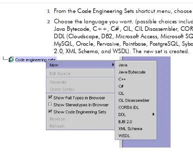
To add a new set
1 From the Code Engineering Sets shortcut menu, choose New. 2 Choose the language you want. (possible choices include: Java,
Java Bytecode, C++, C#, CIL, CIL Disassembler, CORBA IDL, DDL (Cloudscape, DB2, Microsoft Access, Microsoft SQL Server, MySQL, Oracle, Pervasive, Pointbase, PostgreSQL, Sybase), EJB 2.0, XML Schema, and WSDL). The new set is created.
Figure 1 -- Code engineering language options
Edit sets in the Round Trip Set dialog box. To open this dialog box
• Choose Edit from the set shortcut menu.
CIL Disassembler C# +
XML Schema - +
WSDL - +
C# C# +
EJB 2.0 - +
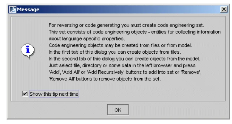
If you are performing round trip for the first time, the tip message box appears.
Figure 2 -- Code Engineering Sets tip message box
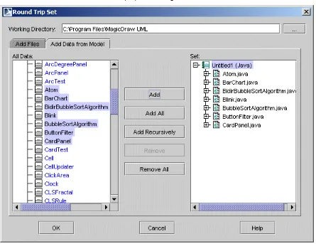
Disable the tip message box by deselecting the Show this tip next time check box. The Round Trip Set dialog box allows you to manage entities to be added/removed to your set.
Figure 3 -- Round Trip Set dialog box. Add files tab
The Add Files tab helps you manage the files of source code involved in your code engineering set.
The Add Data from Model tab helps you manage elements located in the UML model.
Figure 4 -- Round Trip Set dialog box. Add data from model tab
The All Data list contains the hierarchy of UML model packages with model elements (or other packages) inside of them. Your code engineering set can be combined out of model and code elements.
The following buttons are available in the Round Trip Set dialog box: Element name Function
Working Directory
Indicates files and required sub-directories, where a code generation output goes. Type a path manually or by browsing in the directory tree, by clicking the ‘…’ button.
All files Helps you find directories with the source files for the set.
Files of type Contains possible file name extensions for the chosen language.
Add The selected file in the All Files or All Data list is added to the set.
Add All All files in the opened or selected directory are added to the set.
Add Recursively All files in the selected directory and its subdirectories are added to the set.
G E N E R A T E C O D E
You may generate code for the selected and prepared set and directly for model elements.
Code Generation for Set
Start code generation once the set or sets are prepared. For more details about creating and editing sets, see Section “Code Engineering Sets” on page 1-6.
• Choose Generate from the Code Engineering Sets item shortcut
menu. It allows code generating for all created sets.
• Choose Generate from the selected set shortcut menu. It allows code
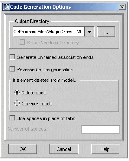
generating only for the selected set. The Code Generation Options dialog box appears.
Figure 5 -- Code generation options dialog box.
The Code Generation Options dialog box allows you to specify the way your code will be generated.
Once generating options are specified for the set, code can be generated.
Code Generation for Model Element
All the classes contained in the component will be written to one file. However, code for the class can be generated in a different way. Select the class you wish to generate in the browser Data package and click Generate in the class shortcut menu. For packages and components, you may also select Generate, but you will not be able to specify the generation options. All the options related to that task will be set
according to the default values. Box name Function
Output Directory Type the directory where the generated files will be saved.
'...' The Set Output Directory dialog box appears. Select the directory for the generated files.
Set as Working
Directory The output directory is set as a working directory and files are saved to the working directory.
Generate unnamed association ends
Gives the names to the unnamed association ends and generates them.
Reverse before
generation Changes your model according to changes in the existing code. WARNING: Exercise caution when selecting the Reverse before generation check box. If the model differs from the code, all differences in the model will be discarded. In such cases, you will lose some your work.
If element deleted from model
To influence the structure of generated code, click one of the following option buttons:
• Delete code. The representation of deleted entities will be deleted
from the code file.
• Comment code. Deleted entities will be commented in the code file.
Use spaces in place of tabs
When selected, spaces (instead of tabs) will be written to the code file.
Number of
spaces Specify the number of spaces to be written.
OK The Messages Window appears, displaying how code files are being generated. The Messages Window informs you of problems and errors (mainly file access and syntax errors) found in the code generation process and generation summary. You are also prompted to confirm that you wish to overwrite the file if the output directory already contains one with the same name.
Cancel Closes the dialog box without saving changes.
If you have chosen framework generation for a single class or for packages, the Code Generation Options dialog box does not appear. The code is generated according to the default values.
If no errors occurred, you may view the results with your favorite file viewer or programming environment. Look for the files in the directory that you specified as your Working directory in the Round trip set dialog box or in the Project Options dialog box. Additional sub-directories could be created.
R E V E R S E
A reverse is an opposite operation to the code generation. The existing code can be converted to UML models with the help of MagicDraw reverse mechanism.
Prepare the sets in the exact same way that you did for code generation (see Section “Code Engineering Sets” on page 1-6)
• Choose Reverse from the Code engineering sets item shortcut
menu. It allows code reversing for all already created sets.
• Choose Reverse from the selected set shortcut menu.
The UML model for the component can be reversed in the same way. Just select the component you are interested in from the browser and click Reverse on it shortcut menu.
Models can be reversed without creating a set.
To reverse a model without creating a set
1 From the Tools menu, choose Quick Reverse. The Round Trip Set
dialog box appears.
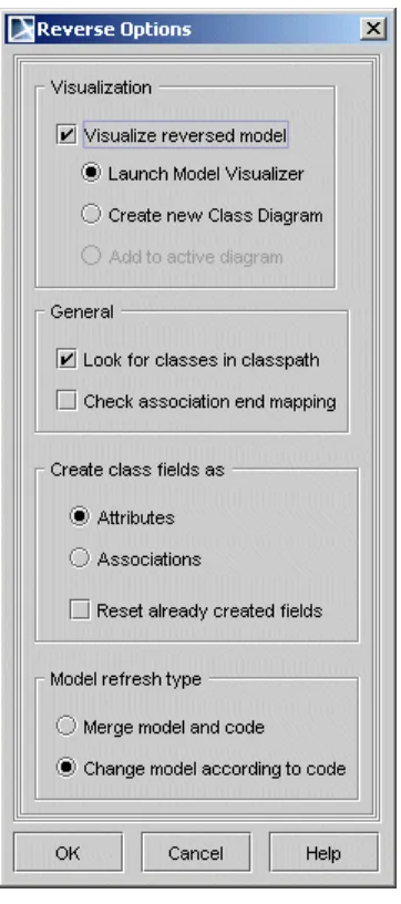
3 Click OK. The Reverse Options dialog box appears.
Figure 6 -- Reverse options dialog box
Element name Function
GENERAL
Visualization Classes that are created while reversing can be added to a class diagram in three separate ways. Also sequence diagram for Java method implementation can be created.
Launch Model Visualizer
After reversing, the Model Visualizer dialog box appears. It will assist you in creating a class diagram or sequence diagram (Java only) for newly created entities.
Create new class diagram
After reversing, the Create Diagram dialog box appears. Create a new diagram where the created entities will be added.
Add to active diagram After reversing, all created entities will be added to the current opened diagram.
Look for classes in classpath
If you have a code set combined from several files, you may see changes you wish to model without reversing all the code. Only changed files should be reversed. This type of reversing can be done by clicking the Refresh button on the set shortcut menu, or by performing model refresh from the Code Engineering Sets dialog box.
J A V A R E V E R S E T O S E Q U E N C E D I A G R A M
Java reverse to Sequence diagram functionality allows visualizing Java method implementation with UML Sequence diagram. Created from method Sequence diagram cannot be updated, every time new diagram should be generated.
To launch Sequence Diagram from Java Source Wizard and specify options
needed for the reverse
• You are able to reverse any operation from the Browser: right click
an operation, choose Reverse Implementation and launch Sequence diagram from Java Source Wizard.
• From the Tools menu, choose Model VIsualizer, and then choose
Sequence Diagram from Java Source WIzard.
• When reversing, in the Reverse Options dialog box, choose
Launch Model Visualizer and then choose Sequence Diagram from Java Source Wizard.
The more detailed example of how this functionality works, see MagicDraw
Tutorials.pdf, which is locate in <MagicDraw installation directory>, manual folder. Check association
end mapping Association end and attribute type are mapped during the generation.
CREATE CLASS FIELDS AS
Attributes Class fields are represented in model as attributes.
Associations Class fields are represented in model as association ends.
Reset already created fields
Select this option if you want to keep already created UML representation (attribute or association) for class fields.
MODEL REFRESH TYPE
Merge model and
code The model elements are updated by code. Elements that do not exist in the code will not be removed from the model.
Change model according to code
Model will be created strictly by code. Entities in the model that do not match entities in the code will be discarded.
OK Saves changes and exits the dialog box.
Cancel Exits dialog box without saving changes.
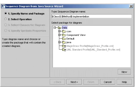
Sequence Diagram from Java Source Wizard
Sequence Diagram from Java Source Wizard is the primary tool for reversing s sequence diagram from Java method. It contains four steps that are described below.
S T E P 1 S
P E C I F YN
A M E A N DP
A C K A G E.
Figure 7 -- Sequence Diagram from Java Source Wizard
In this step, type the name of the newly created sequence diagram. Be default class name and selected operation name with a word “implementation” will be included in the sequence diagram name.
S T E P 2 S
E L E C TO
P E R A T I O NIn this step, select an operation for which you want to create a sequence diagram. If the Java source file is not shown you must select it manually.
S T E P 3 S
E L E C TC
L A S S E S F O RD
I A G R A MIn the Select Classes for Diagram step, all referenced classes are displayed. Select the desired classes and instances of those classes will be added into diagram with call messages to them.
• Select the Analyze and split long expressions in diagram check
box if expression contains calls and cannot be displayed as call message. Then every call will be shown as separate call message with temporary variable initialization.
• Select the Create return message check box, if you want to display
return message for every call message.
• Select the Wrap message text check box and specify the maximum
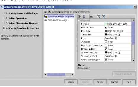
S T E P 4 S
P E C I F YS
Y M B O L SP
R O P E R T I E SFigure 8 -- Sequence Diagram from Sequence Wizard. Specify Symbols Properties
G L O B A L O P T I O N S F O R C O D E
E N G I N E E R I N G
Code engineering options for all sets in your project
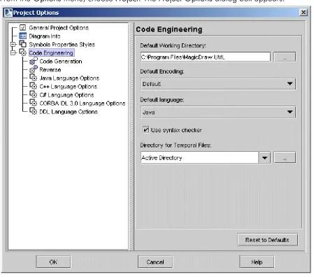
From the Options menu, choose Project. The Project Options dialog box appears.
Figure 9 -- Project Options dialog box
The Project Options dialog box has two main collections of customizable options, which are represented by the hierarchy tree on the left side of the dialog box:
• Styles – expands the tree hierarchy of all the styles defined within the
project. You may use as many of these styles as you wish. See MagicDraw main User’s Manual, working with Projects Section.
• Code engineering – these options are found on the right side of the
• Default Working Directory list box - type the name or browse by
clicking the button in the working directory.
• Default language drop-down box – select the default generation
language.
• Use Syntax Checker check box – when selected, the syntax
checker runs while Code Engineering is executed. Tab name Description
Code
generation Set code generation options using the fields listed in the right side of the Project options dialog box. The Code generation area contains boxes that have the same functionality as in the Code generations options dialog box (see Section “Generate Code” on page 1 -9).
Reverse Set reverse options for all reverse actions of the project using the options listed on the right side of the Project options dialog box. The Reverse area contains boxes that have the same functionality as in the Reverse options dialog box (see Section “Reverse” on page 1 -11).
Tab name Element name Function
Java Language Options Set the
generated code style for Java programming languages in the Default language field found on the right side of the Project Options dialog box.
Generate opening bracket in new line
Opens a bracket in the new line that is being generated.
Generate spaces Generates spaces inside an assignment and other operators.
Use JavaDoc for
documentation Generates javadoc documentation for commenting the code.
Generate empty documentation
Comment brackets are placed in your code, unless class in the model has no documentation.
Automatic “import” generation
Automatic generation of "import" sentences according to classes that are referenced in the generated class.
Class count to generate import on demand
Specify number of classes imported from a single package until all statements importing a single class are substituted with a statement importing an entire package.
Java
Documentation Properties
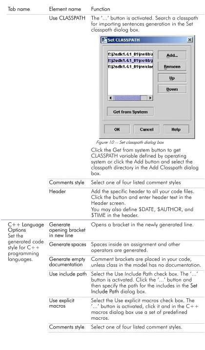
Use CLASSPATH The ’...’ button is activated. Search a classpath for importing sentences generation in the Set classpath dialog box.
Figure 10 -- Set classpath dialog box
Click the Get from system button to get CLASSPATH variable defined by operating system or click the Add button and select the classpath directory in the Add Classpath dialog box.
Comments style Select one of four listed comment styles
Header Add the specific header to all your code files. Click the button and enter header text in the Header screen.
You may also define $DATE, $AUTHOR, and $TIME in the header.
C++ Language Options
Set the
generated code style for C++ programming languages.
Generate opening bracket in new line
Opens a bracket in the newly generated line.
Generate spaces Spaces inside an assignment and other operators are generated.
Generate empty documentation
Comment brackets are placed in your code, unless class in the model has no documentation.
Use include path Select the Use Include Path check box. The ’...’ button is activated. Click the ’...’ button and then specify the path for the includes in the Set Include Path dialog box.
Use explicit
macros Select the Use explicit macros check box. The ’...’ button is activated, click it and in the C++ macros dialog box use a set of predefined macros.
Header Add the specific header to all your code files. Click the “…” button and enter header text in the Header screen.
You may also define $DATE, $AUTHOR, and $TIME in the header.
CORB IDL 3.0 Language Options
Generate
documentation Includes the documentation of an element in the comment.
Generate opening bracket in new line
Opens a bracket in the new line generating.
Generate spaces Spaces inside an assignment and other operators are generated.
Generate empty
documentation Comment brackets are placed in your code, unless class in the model has no documentation.
Comments style Select one of two comment styles.
Header “...” Add the specific header to all your code files. Click the “...” button and enter header text in the Header screen. You may also define $DATE, $AUTHOR, and $TIME in the header.
DDL Language Options
Generate opening bracket in new line
Opens a bracket in the new line generating.
Generate spaces Spaces inside an assignment and other operators are generated.
Generate documentation
Comment brackets are placed in your code, unless class in the model has no documentation.
Header Add the specific header to all your code files. Click the button and enter header text in the Header screen. You may also define $DATE, $AUTHOR, and $TIME in the header.
C# Language Options Set the
generated code style for C# programming languages.
Generate opening bracket in new line
Opens a bracket in the newly generated line.
Generate spaces Generates spaces inside an assignment and other operators.
Generate empty
documentation Comment brackets are placed in your code, unless class in the model has no documentation.
Generate required "using" directives
Automatic generation of "using" directives. This option facilitates the usage of namespaces and types defined in other namespaces.
Concatenate namespace names
If not selected namespace names are separated into several lines.
e.g.
namespace A {
namespace B {
Comments style Select one of the listed comment styles.
Documentation:
• Processor
• Style
• Use C# XMI processor then generates c# xmi documentation for commenting the code.
• Select one of the listed comment styles.
Header Adds the specific header to all your code files. Click the '...' button and type header text in the Header dialog box.
You may also define $DATE, $AUTHOR, and $TIME in the header.
Conditional
Symbols Add the conditional symbols, which can not be recognized and should be skipped during reverse.
Click the '...' button and add conditional symbols in the Define Conditional Symbols dialog box.
Java Documentation Properties dialog box
To open the Java Documentation Properties dialog box
In the Project Options dialog box, Java Language Options and IDL Language Options pane, click the Java Documentation Properties button.
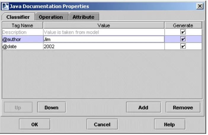
Figure 11 -- Java Documentation Properties dialog box
Box Name Function
Tag Name Type a tag name.
Value Type the value of the tag.
Generate The selected tag will be placed in the generated code as a comment before classifier (class or interface), operation or attribute.
Up Moves the selected item up the list.
Down Moves the selected item down the list.
Add Adds a new item in the list.
Remove Removes the selected item from the list.
OK Saves changes and closes the dialog box.
Cancel Closes the dialog box without saving changes.
Round Trip
MagicDraw round trip keeps your code and model synchronized, and because Round trip traces all the model and code changes, you may freely change entity
specifications without discarding code changes made outside the tool.
For example, Round Trip prevents a job from being damaged by code additions or changes when these steps are followed:
Within the tool, class Base is created.
1 Operation getInstance is added to class. 2 Code is generated
3 With external tool, programmer adds code to that operation. 4 With MagicDraw UML, operations name is changed to Instance. 5 Code is generated.
If the tool rewrites the whole code, these changes are made without corrupting the programmer’s job. The name of the operation is changed, but the internals remain the same.
Round trip catches all changes in your project and controls the following
actions:
• If the source code is not changed, it is not allowed to refresh UML
model. The Refresh command from the set shortcut menu is unavailable.
• If the model is changed but the code remains the same (new
members were added or their headers were changed), refresh is not allowed, and the Refresh command from the set shortcut menu is unavailable. When generating code according to
changes, all changes in the model are written to the signatures of class members, leaving the old implementation in place.
• If the code is changed but the model remains the same, refresh
can be executed: code will be reversed to the UML models. If the Code Generation Options dialog box appears when you are attempting to generate code, you may select a code action that differs from the UML model.
• If the code and model are changed while refreshing, all changes
in the code are treated as new items and added to the model.
• If data in the model file is deleted, it will be restored while
Type Mapping Table
Languages supported by MagicDraw UML have their own built-in types. One language’s type might have no matches in another language, or it might have multiple matches. Additionally, some names are interpreted differently in different languages. When performing code generation, therefore, problems may occur when switching between different languages. To avoid this, MagicDraw UML uses type-mapping tables to manage type-mapping between languages. It describes the rules of how one language’s built-in types are converted to those of another language
Editor Properties dialog box
The Editor Properties dialog box is used for selecting a tool for editing text.
To open the Editor Properties dialog box
Choose the Editor Properties command from the selected set shortcut menu.
Figure 12 -- Editor Properties dialog box
Element name
Type Function
Text Editor Text box Type the path to the text editor.
“…” Button The Select Text Editor dialog box appears. Choose the desired text editor.
Arguments Text box Type values that are passed to the text editor. Arguments: $f - file
$r - row $c - column
OK Button Saves changes and exits the dialog box.
Cancel Button Exits the dialog box without saving changes.
F I L E S O F P R O P E R T I E S
The code can be generated out of prepared UML models. The mapping between the identifiers, used in the UML model and the language to which the model is being generated, should be implemented. This mapping includes the following sections:
• Build-in types (their default values) • Generalization types
• Possible class declarations. Attributes and operations declaration
and visibility modifiers
• Code generation options.
The separate prop file is created for every language that is supported by MagicDraw. Files are located in the <MagicDraw installation directory>/data folder. The file name pattern is lang.prop, where lang stands for the name of the programming language.
Files of language properties are separated into sections where all related elements are grouped. You may edit existing entities, add new ones, and change the default values.
We strongly recommend that you edit default values only. In general, all the sections have the list of possible and default values for the element.
Supported language
File of Properties
JAVA java.prop
C++ C++.prop
CORBA IDL idl.prop
JAVABytecode javabytecode.prop
DDL ddl.prop
CIL cil.prop
CIL Disassembler cil disassembler.prop
C# c#.prop
EJB ejb.prop
EJB 2.0 ejb20.prop
IDL idl.prop
XML Schema xmlschema.prop
MagicDraw UML has the tools that forward engineer UML constructs to DDL script. The resulting DDL script depends on the selected DDL language dialect.
Retrieve DB Info dialog box
IMPORTANT! Since MagicDraw version 9.0, Retrieve DB Info dialog box has been moved to the Round Trip Set dialog box.
The Retrieve DB info function allows you to retrieve the information from the existing database or ODBC source. Database structure is retrieved as UML model, using class diagram elements.
The mapping of the DB to UML is the same as in DDL reverse engineering.
NOTE As the retrieve DB info function uses JDBC bridge, you may need to have JDBC drivers. All types of drivers are valid for making a connection. The driver should be able to retrieve the database metadata information. The same applies to the database; it should be able to provide this information.
To open the Retrieve DB Info dialog box dialog box
1 From the Code Engineering Sets shortcut menu, choose New. 2 Choose DDL and then choose the database vendor you need.
Microsoft SQL Server, MySQL, Oracle, Pervasive, Pointbase, PostgreSQL, Standard SQL, and Sybase.
3 The new set is created.
4 From the created set shortcut menu, choose Edit. The Round Trip
• From the Tools menu, choose Quick Reverse and then choose
DDL and required database vendor. The Round Trip Set dialgo box appears. Select the Reverse from DB option.
Figure 13 -- Retrieve DB Info dialog box
Box name Function
Recently Used Contains the list of the recently used reverse templates. Choose the one you need and click Apply.
DB
Connection URL
The connection URL for the selected profile.
Driver Files Contains .jar and .zip files or directories with JDBC driver’s classes. To choose the files or directories you want to add or remove, click the “...” button. The Select Files and/or Directories dialog box appears.
F O R W A R D E N G I N E E R I N G T O D D L S C R I P T
This section describes to what data model constructs MagicDraw constructs are converted.
Packages
The Database is represented as a Package with the <<database>> stereotype. Each View or Table can be assigned to a Schema where the Schema is represented as a Package with the <<schema>> stereotype.
Driver Class Contains the connection driver class.
Click the “...” button and the list of available driver classes that are available in the selected driver files is displayed.
NOTE Only in the files that are selected in the Driver Files list, the system searches for driver classes .
Username Type the username to connect to the database.
Password Type the password to connect to the database.
Catalog Contains a name of the selected Catalog.
To retrieve the list of available Catalogs from the database, click the “...” button and select the catalog. The catalog name appears in the Catalog text box.
NOTE Only when all other properties in this dialog box are correctly defined, the list of catalogs can be retrieved.
Schema Contains a name of the selected Schema.
To retrieve the list of available Schemas from the database, click the “...” button and select the schema. The schema name appears in the Schema text box.
NOTE Only when all other properties in this dialog box are correctly defined, the list of schemas can be retrieved.
Property Name
The name of the JDBC driver property.
NOTE: If using Oracle drivers, while retrieving db info from Oracle db:
• To retrieve comments on table and column, set property as
remarks=true.
• To connect to a db as sysdba, set property as
internal_logon=sysdba.
Debug JDBC Driver
If selected, all output from a JDBC driver will be directed to Message Window.
Relode Driver By default, the Reload Driver check box is selected. If you want that driver to not be reloaded, clear the check box.
A Package, depending on a package stereotype, is mapped to one of the following DDL constructs:
• A Database, if the package has the <<database>> stereotype.
Elements: CREATE DATABASE <database_name> Database name is equal to the package name.
• A Schema, if the package has the <<schema>> stereotype.
Elements: CREATE SCHEMA
[<database_name>.]<schema_name>
Schema name is equal to the package name. Schema database name is the name of a package that contains schema package.
• Otherwise it is not mapped.
NOTE If a package has no stereotype and the EnableDefaultStereotypes property is true, the <<database>> stereotype is used for the first level packages, and the <<schema>> stereotype is used for the second level packages.
Figure 14 -- Package mapping example
DLL script, generated for example showed in Package mapping example12, creates one Database and two Schemas:
CREATE DATABASE DB1;
CREATE SCHEMA DB1.Schema1; CREATE SCHEMA DB1.Schema2;
Classes
A class, depending on class stereotype, is mapped to one of the following DDL constructs:
• Table, if the class has the <<table>> stereotype.
Elements: CREATE TABLE [<schema_name>.]<table_name> (<column_and_constraint_list>)
Table name is equal to the class name. Table schema name is the name of package that contains table class.
<<database>>
DB1
<<schema>>
Schema1
<<schema>>
• View, if the class has the <<view>> stereotype.
Elements: CREATE VIEW [<schema_name>.]<view_name> [(<column_list>)] AS SELECT <derived_column_list> FROM <table_list>.
View name is equal to the class name. The view schema name is the name of a package that contains view class. Table list within view “FROM” clause are derived from associations between the view class and tables classes.
• Otherwise it is not mapped.
NOTE If a class has no stereotype and the EnableDefaultStereotypes property is true, the class is treated as a class with the <<table>> stereotype.
Figure 15 -- Class mapping example
DLL script, generated for classes is showed in Class mapping example13. It has two Table definition statements (CREATE TABLE) and view definition statement (CREATE VIEW):
CREATE TABLE Person ( id INTEGER NOT NULL,
socialId NUMBER(10) NOT NULL, lastName VARCHAR(20) NOT NULL, firstName VARCHAR(10) NOT NULL, sex CHAR(1)
);
CREATE TABLE Account (
accountNo INTEGER NOT NULL, balance FLOAT(5) DEFAULT 0.0, personalId INTEGER NOT NULL); CREATE VIEW ImportantClient
AS SELECT P.*, Account.balance as total FROM Person, Account;
Account
-accountNo : INTEGER -balance : FLOAT (5) = 0.00 -personId : INTEGER
<<table>>
Person
-firstName : VARCHAR (10) -id : INTEGER
-lastName : VARCHAR (20) -sex[0..1] : CHAR (1) -socialId : NUMBER (10)
<<view>>
ImportantClient
-total = Account.balance -P.*
-id,firstname,lastname
Attributes
An attribute of a class with the <<table>> or the <<view>> stereotype, depending on an attribute stereotype, is mapped to one of the following DDL constructs:
• A Column of a Table, if the class that contains an attribute has the
<<table>> stereotype.
A Column name is equal to the name of an attribute. A Column type is equal to the type of an attribute. Column default value is equal to the initial value of an attribute (if any).
• A Column of a View, if the class that contains an attribute has the
<<view>> stereotype.
Elements: [<column_expression> AS] <column_name> A Column name is equal to the name of an attribute. Column expression is equal to the initial value of an attribute (if any).
Figure 16 -- Attributes mapping example
Col1 attribute of the Table1 class (see Attributes mapping example14) is mapped to the col1 column of a Table1 table, and col1 attribute of the View1 class is mapped to the col1 column of a View1 view. There is DDL script for attributes mapping example:
CREATE TABLE Table1 (
col1 INTEGER DEFAULT 123 );
CREATE VIEW view1
AS SELECT Table1.col1 AS v1 FROM Table1;
Operations
An operation (method) of a class with the <<table>> stereotype, depending on an operation’s stereotype, is mapped to one of the following DDL constructs:
• An Index for a Table, if the operation has the <<index>>
stereotype;
Elements: CREATE INDEX [<schema_name>.]<index_name> ON <table_name>(<column_list>)
An Index name is equal to the name of an operation. Names of comma-delimited set of column for the index are equal to the parameter names of an operation.
<<table>>
Table1
-col1[0..1] : INTEGER = 123 -col2 : INTEGER
<<view>>
View1
• Tags with names: trigger action time, trigger event and triggered
action has meaning in DDL CG have meaning in the DDL CG if are specified for an operation with stereotype <. The
"implementation" tag specified for operation with stereotype trigger has no meaning for the DDL code generation since MD 6.0 version. The "implementation" tag was split to three tags: "trigger action time", "trigger event" and "triggered action". Values of these tags will be used then generating definition of a trigger. ::= CREATE TRIGGER ON [ REFERENCING ]
• A constraint, if the Operation has the <<PK>>, <<FK>>,
<<unique>>, or <<check>> stereotype.
Elements: [ALTER TABLE <table_name> ADD] CONSTRAINT <constraint_name>
Constraint name is equal to the name of an operation.
• PRIMARY KEY (<pk_column_list>)
Primary key column list contains all attributes with the <<PK>> stereotype.
• FOREIGN KEY (<column_list>) REFERENCES
<ref_table_name>[(<ref_column_list>)]
Foreign key column list, referenced table, and referenced column list depends on an association with the same name as the name of a foreign key operation. Referenced table name is equal to the name of an associated class. Foreign key column list is equal to the name of an association end A. Referenced column list is equal to the name of an association end B (if any).
• UNIQUE (<unique_column_list>)
Unique constraint element <unique_column_list> is generated from operation’s parameter names.
• CHECK (<check_expression>)
Check constraint element <check_expression> is generated from tag named Implementation.
Otherwise it is not mapped.
TriggerNamePrefix property specifies an optional naming standard that is added to the beginning of the name for each generated trigger.
Figure 17 -- Operations mapping example
An example of the DDL script for operations mapping:
CREATE TABLE TableB ( id INTEGER NOT NULL
CONSTRAINT checkColumn CHECK(/*<check_expression>*/), b1 INTEGER NOT NULL,
b2 INTEGER NOT NULL,
CONSTRAINT pk1 PRIMARY KEY (id),
CONSTRAINT checkTable CHECK(/*<check_expression>*/), CONSTRAINT unique1 UNIQUE(b1,b2)
);
CREATE TABLE TableA ( fk INTEGER NOT NULL, a1 INTEGER DEFAULT 123,
CONSTRAINT fk1 FOREIGN KEY (fk) REFERENCES TableB(id) );
CREATE INDEX indexOnA1 ON TableA(a1);
CREATE TRIGGER trigger1 ON TableA /*<triggered_SQL_statement>*/;
Association cardinalities
ON E-T O-M A N Y ( 1 : N ) A S S O C I A T I O N
One-to-many (1:N) association is mapped to relationship.
B A
Figure 18 -- Cardinalities of 1:N association
For 1:N association cb role allowed cardinalities are 0, 1, N. For ca role allowed cardinalities are 0, 1 (see Cardinalities of 1:N association16 -- Cardinalities of 1:N association).
Concrete cardinalities of ca and cb roles are mapped to different data model constraints (if any):
5 If cb role does not allow N cardinality, the UNIQUE constraint is
assigned to b_id column.
When b_id column has the UNIQUE constraint, every A class references a unique B class (if any). Given B class is associated with the unique A class (if any). This means that cb role has no N cardinality.
6 If ca role does not allow 0 cardinality, NOT NULL constraint is
assigned to b_id column.
When b_id column has NOT NULL constraint, every A class references some B class. This means that ca role does not allow 0 cardinality.
Figure 19 -- 1:N association and mapped representation
Script creating 1:N association:
CREATE TABLE Company (
id INTEGER NOT NULL PRIMARY KEY);
CREATE TABLE Employee (c_id INTEGER NOT NULL,
CONSTRAINT FK_1 FOREIGN KEY (c_id) REFERENCES Company (id));
ON E-T O-O N E ( 1 :1) A S S O C I A T I O N
One-to-one (1:1) association is handled as a special case of one-to-many relationships, where cb role allowed cardinalities are 0, 1 and ca role allowed cardinalities are 0, 1 (see Cardinalities of 1:N association16 -- Cardinalities of 1:N association).
<<table>>
A
-b_id : INTEGER
<<FK>> +FK_1( b_id )
<<table>>
B <<PK>> -id : INTEGER
FK_1 -b_id
?
-id
?..1
Employee Company
1..* 1
<<table>>
Employee
-c_id : INTEGER
<<FK>>
+FK_1( c_id )
<<table>>
Company
<<PK>>
-id : INTEGER
FK_1 -c_id
0..*
-id
1:1 association is mapped to a relationship. The 1:1 cardinality must be forced through constraints.
Figure 20 -- 1:1 association and mapped representation
A script that creates a 1:1 association:
CREATE TABLE Company (
id INTEGER NOT NULL PRIMARY KEY );
CREATE TABLE Director (
c_id INTEGER NOT NULL UNIQUE,
CONSTRAINT FK_1 FOREIGN KEY (c_id) REFERENCES Company (id) );
Nevertheless, this DDL script with these constrains does not ensure a strict 1:1
association – Company table may have rows that do not have their counterpart rows within Director table.
MA N Y-T O-M A N Y ( N : M ) A S S O C I A T I O N
Many-to-many (N:M) associations are not handled by MagicDraw UML.
Inheritance
SI N G L E I N H E R I T A N C E
Figure 21 -- Single Inheritance and mapped representation
A script that creates a single inheritance:
CREATE TABLE Employee (
id INTEGER NOT NULL PRIMARY KEY
Company Director 1 1 <<table>> Director <<unique>>
-c_id : INTEGER
<<FK>>
+FK_1( c_id )
<<table>> Company
<<PK>>
-id : INTEGER
FK_1 -c_id 0..1 -id 1 Employee Director <<table>> Director <<PK>>
-id : INTEGER
<<FK>>
+FK_1( id )
<<table>>
Employee
<<PK>>
-id : INTEGER
FK_1 -id
1 -id
);
CREATE TABLE Director (
id INTEGER NOT NULL PRIMARY KEY,
CONSTRAINT FK_1 FOREIGN KEY (id) REFERENCES Employee(id) );
NOTE The Employee table may have rows that do not have their counterpart rows within Director table.
MU L T I P L E I N H E R I T A N C E
The mapping of a multiple inheritance is similar to the mapping of a single inheritance.
Figure 22 -- Multiple Inheritance and mapped representation
A script that creates a multiple inheritance:
CREATE TABLE Base1 (
id INTEGER NOT NULL PRIMARY KEY );
CREATE TABLE Base2 (
id INTEGER NOT NULL PRIMARY KEY );
CREATE TABLE Derived ( b1_id INTEGER NOT NULL, b2_id INTEGER NOT NULL, PRIMARY KEY (b1_id, b2_id),
CONSTRAINT FK_1 FOREIGN KEY (b1_id) REFERENCES Base1(id), CONSTRAINT FK_2 FOREIGN KEY (b2_id) REFERENCES Base2(id) ); Base2 Base1 Derived <<table>> Derived <<PK>>
-b1_id : INTEGER -b2_id : INTEGER
<<FK>>
+FK_1( b1_id ) +FK_2( b2_id )
<<table>>
Base2
<<PK>>
-id : INTEGER
<<table>>
Base1
<<PK>>
-id : INTEGER
Not supported UML constructs
Constructs that are not mapped into DDL script, because this would lead to a generation of an illegal DDL code:
• Duplicated names are not allowed.
NOTE Uppercase and lowercase letters are equivalent.
• Database package cannot contain two schema packages with
the same name.
• Schema package cannot contain two UML constructs that are
mapped to the schema elements such as table classes, view classes, index operations, and trigger operations that have the same name.
• Table class cannot have two column attributes or constraint
operations with the same name.
• View class cannot have two column attributes with the same
name.
• Table class cannot have two operations with the <<PK>>
stereotype, because a table can have only one primary key (if any).
• References to non-existing columns are illegal.
• The parameter name of an operation with a DDL stereotype
(<<index>>, <<trigger>>, <<PK>>, <<FK>>,
<<unique>>, <<check>>) must be the name of an existing column attribute.
• Referenced column name list, represented as an association
role name, must contain names of existing column attributes.
• Supported attribute multiplicity can be [not specified], [0..1], and
[1]. All other attribute multiplicities are not supported.
R E V E R S E E N G I N E E R I N G F O R D D L S C R I P T
Database
A Database is a system for a data storage and controlled access to the stored data. It is the biggest construct that a data model supports.
A package, which is used with the <<database>> stereotype, represents a database in the MagicDraw UML model. The database that is modeled as a package must have a name.
Example of a DDL script:
CREATE DATABASE BankDB;
Representation using UML concepts:
Figure 23 -- Database example
See also: CurrentDatabaseName property
Schema
A package with the <<schema>> stereotype within the package with the <<database>> stereotype represents a database schema.
Example of a DDL script:
CREATE SCHEMA Public;
Example rewritten using a qualified schema name “BankDB.Public”:
CREATE SCHEMA BankDB.Public;
Representation using UML concepts:
Figure 22 – Schema example
NOTE There can be more than one schema associated to a database. See also: CurrentSchemaName property
<<database>>
BankDB
Table
A table is the basic modeling structure of a relational database. It represents a set of records of the same structure, also called rows. Each of these records contains data. Information about the structure of a table is stored in the database itself.
A class with the <<table>> stereotype represents a relational table in a schema of a database.
Example of a DDL script for table:
CREATE TABLE Account (
accountNo INTEGER NOT NULL, personId INTEGER NOT NULL,
balance FLOAT(5) DEFAULT 0.0 NOT NULL );
This example may be rewritten instead of “Account” using qualified table name “BankDB.Public.Account”.
Representation using UML concepts:
Figure 24 -- Table example
Hosting the table in the schema package creates an association of a table to a schema.
Column
A table contains columns. A column must have a defined name and data type; a default value and several constraints are optional.
Example: balance FLOAT(5) DEFAULT 0.0
A column is represented as an attribute. A name, data type, and initial value of an attribute are set according to the name, data type, and default value of the column. The stereotype of an attribute is set according to column constraints. Stereotype can be not specified, <<unique>>, or <<PK>>.
<<table>>
Account
(BankDB.Public)
Constraint
A constraint is a rule applied to the structure of a database. This rule extends the structure of a database and can be applied to a column or a table.
In general, a constraint may be represented as an operation with an appropriate stereotype and parameter list containing the list of column names that constraint concerns. An operation name is equal to the name of a constraint, but, when a constraint has no name specified, operation is unnamed.
All listed constraints (null, not null, uniqueness, primary key, foreign key, and check) are implemented in the following example:
CREATE TABLE Person (
id INTEGER NOT NULL PRIMARY KEY, socialId NUMBER(10) NOT NULL UNIQUE
CONSTRAINT checkSocialId CHECK(socialId>0), lastName VARCHAR(20) NOT NULL,
firstName VARCHAR(10) NOT NULL, sex CHAR(1) NULL
);
CREATE TABLE Account ( accountNo INTEGER NOT NULL,
balance FLOAT(5) DEFAULT 0.0 NOT NULL CONSTRAINT checkBalance CHECK(balance>=0), personalId INTEGER NOT NULL,
CONSTRAINT PK_Account0 PRIMARY KEY (accountNo, personalId),
CONSTRAINT FK_Account1 FOREIGN KEY (personalId) REFERENCES Person(id) );
Representation using UML concepts:
Figure 25 -- Constraints example
NO T N U L L, NU L L
NOTE A Null constraint is not defined in SQL-92 standard but some dialects use it. Microsoft SQL Server allows setting a flag, which indicates that all columns have Not Null constraint, which is set by default. A Null constraint that is assigned for a column overrides the default Not Null constraint and allows null values.
Not Null constraint indicates that the value for an attribute is required; Null constraint indicates that the value is optional.
firstName VARCHAR(10) NOT NULL, sex CHAR(1) NULL
Not null constraint and null constraint are modeled as the multiplicity of an attribute. Multiplicity may be indicated by placing a multiplicity indicator in brackets after the name of an attribute. A multiplicity of 0..1 provides a possibility of null values, for an example: sex [0..1]: CHAR(1)
In the absence of a multiplicity indicator, an attribute holds exactly one value. See also: ColumnDefaultNullability, AttributeDefaultMultiplicity,
GenerateNullConstraint, GenerateNotNullConstraint properties. Example of a DDL script:
CREATE TABLE NullableExample ( dontcare INTEGER,
optional INTEGER NULL, required INTEGER NOT NULL );
Representation using UML concepts:
Figure 26 -- Not null, null constraints example
UN I Q U E N E S S
Uniqueness constraint indicates that the value of a column must be unique within the table.
Uniqueness constraint is modeled as the <<unique>> stereotype associated with an attribute and an operation with the <<unique>> stereotype and a parameter list. Example of a DDL script:
CREATE TABLE UniqueExample (
col1 INTEGER CONSTRAINT uniqueColumn UNIQUE, col2 INTEGER,
col3 INTEGER,
CONSTRAINT uniqueCombination UNIQUE (col2, col3) );
Representation using UML concepts:
Figure 27 -- Unique constraint example
PR I M A R Y KE Y
Primary Keys uniquely identify a row in a table. They mark an attribute as the Primary Key or the part of the Primary Key. The attribute must be of a scalar type. If more than one Primary Key attribute is identified, a concatenated primary key is generated.
A Primary Key is represented as the <<PK>> stereotype on an attribute and/or an operation with the <<PK>> stereotype and the parameter list.
Example of a DDL script:
CREATE TABLE PKColumnExample (
col1 INTEGER Constraint pkColumn PRIMARY KEY );
CREATE TABLE PKColumnExample ( col2 INTEGER,
col3 INTEGER,
CONSTRAINT pkCombination PRIMARY KEY (col2, col3) );
Representation using UML concepts:
Figure 28 -- Primary key constraint examples
FO R E I G N KE Y
A Foreign Key constraint represents a relationship to another table.
Foreign Key constraint is represented as an operation with the <<FK>> stereotype and parameter list, and an association to the target table.
CONSTRAINT <fkname> FOREIGN KEY (<linkCols>) REFERENCES <targetTable>(<targetCols>)
UML concept FK element Example
Operation name <fkname> fk
Operation parameters
list <linkCols> l1,l2
Association name <fkname> fk
Association end A class <linkTable> FKLink
Association end A name <linkCols> l1,l2
Association end A
navigable False
<<table>>
PKColumnExample <<PK>>
-col2 : INTEGER -col3 : INTEGER
<<PK>>
Example of a DDL script:
CREATE TABLE FKTarget1( t INTEGER PRIMARY KEY );
CREATE TABLE FKLink1(
r INTEGER CONSTRAINT fk1 REFERENCES FKTarget1(t), );
CREATE TABLE FKTarget ( t1 INTEGER,
t2 INTEGER,
PRIMARY KEY (t1, t2) );
CREATE TABLE FKLink ( r1 INTEGER, r2 INTEGER,
CONSTRAINT fk2 FOREIGN KEY (r1,r2) REFERENCES FKTarget(t1,t2) );
Representation using UML concepts:
Figure 29 -- Foreign key constraint example
CH E C K
The Check constraint checks the value of data according to a given expression.
The Check constraint is represented as an operation with the <<check>> stereotype. Operation’s name is equal to the name of the check constraint or, if the constraint name is not specified, the name “unnamed” is generated.
There are a column check constraint and table check constraint:
For column check constraint operation’s parameter list contains one parameter with the Association end B class <targetTable> FKTarget
Association end B name <targetCols> t1,t2
Association end B
navigable True
Example: Table check constraint operation has no parameters.
CREATE TABLE CheckExample (
balance INTEGER CONSTRAINT checkBalance CHECK(balance>=0) start INTEGER, -- period start balance
income INTEGER CHECK(income>=0), -- unnamed check constraint outcome INTEGER,
CONSTRAINT checkInOut CHECK(start+income-outcome = balance) );
Representation using UML concepts:
Figure 30 -- Check constraint example
U N N A M E D C O N S T R A I N T R E P R E S E N T A T I O N
A S A S T E R E O T Y P E O F A N A T T R I B U T E
Some column characteristics (column primary key constraint, column uniqueness constraint) that apply to one specific column may be represented as stereotype of that attribute.
Example DDL script:
CREATE TABLE ConstraintExample1 ( col1 INTEGER PRIMARY KEY,
col2 INTEGER UNIQUE );
Representation using UML concepts:
Figure 31 -- Column with unnamed constraint example
Only one constraint can be represented as stereotype, because only one stereotype can be assigned for the attribute. If there are other constraints, they should be represented as operations.
Although attribute may have several such constraints assigned, in practice there is no need for more than one. If attribute has primary key constraint it is unique too.
Example DDL script:
<<table>>
ConstraintExample1
<<PK>>
-col1 : INTEGER
<<unique>>
-- here unique constraint is unnecessary CREATE TABLE ConstraintExample2 (
col1 INTEGER PRIMARY KEY UNIQUE );
Representation using UML concepts:
Figure 32 -- Column with two unnamed constraints example
Index
An Index is a physical data structure that speeds up the access to data. It does not change the quality or the quantity of data retrieved. The index specifies the columns included and optionally the uniqueness of the index. An index can include multiple columns or just a single column.
An index is represented as an operation with the <<index>> stereotype and parameter list. The operation name is equal to the index name and the parameter list of the operation is a column names for the index. The uniqueness of the index is ignored (not mapped).
DDL script for an index example that creates the Person table and two indexes:
CREATE TABLE Person (
id INTEGER NOT NULL PRIMARY KEY, socialId NUMBER(10) NOT NULL UNIQUE, lastName VARCHAR(20) NOT NULL,
firstName VARCHAR(10) NOT NULL, sex CHAR(1)
);
CREATE UNIQUE INDEX bySocialId ON Person(socialId); CREATE INDEX byName ON Person(lastName,firstName);
Representation using UML concepts: <<table>>
ConstraintExample2
<<PK>>
-col1 : INTEGER
<<unique>>
+unnamed1( col1 )
<<table>>
Person
-firstName[1] : VARCHAR ( 10 ) -lastName[1] : VARCHAR ( 20 ) -sex : char ( 1 )
<<PK>>
-id[1] : INTEGER
<<unique>>
-socialId[1] : NUMBER ( 10 )
<<index>>
Figure 33 -- Index example
Trigger
A trigger is an activity executed by the DBMS as a side effect or instead of a modification of a table or view to ensure consistent system behavior on data operations.
A Trigger is represented as an operation with the <<trigger>> stereotype. DDL script for trigger example that creates trigger:
CREATE TRIGGER logActions BEFORE INSERT OR DELETE OR UPDATE ON Person
<triggered SQL statement>;
Representation using UML concepts:
Figure 34 -- Trigger example
View
A View is a construct for creating a virtual table based on one or more existing tables or views.
A class with the <<view>> stereotype represents a view in a schema of a database. The View column is modeled as an attribute. Relationships between the View and its underlying tables (“FROM” clause) are modeled as associations. Referenced table alias is modeled as the name of an association, referenced column list as a name of
association role.
View element UML concept Script example
View Class with the <<view>> stereotype
CREATE VIEW
View name Class name
Column Attribute
Column name Attribute name
Derived column Attribute
<<table>> Person
...
<<trigger>>
+logActions()
DDL script for view example:
CREATE TABLE Person ( id INTEGER NOT NULL,
socialId NUMBER(10) NOT NULL, lastName VARCHAR(20) NOT NULL, firstName VARCHAR(10) NOT NULL, sex CHAR(1)
);
CREATE TABLE Account (
accountNo INTEGER NOT NULL,
balance FLOAT(5) DEFAULT 0.0 NOT NULL, personalId INTEGER NOT NULL
);
CREATE VIEW ImportantClient
AS SELECT P.*, Account.balance as total
FROM Person as P(id,firstName,lastName), Account WHERE balance >= 1000000.00 AND personId = P.id;
Representation using UML concepts: – <expression> AS
<name> default value <expression>, name <name>
Account.balance AS total
– * Attribute name *
–<tablename>.* Attribute name P.*
–<columnname> Attribute name Balance
–
<tablename>.<columnna me>
Attribute name <columnname> and default value
<tablename>.<columnna me>
Account.balance
–<expression> Generated unique attribute name and default value <expression>
Table reference Association
Referenced table alias Association name P
Figure 35 -- View example
D D L D I A L E C T S
This section reviews DDL implementations from different vendors. Specific
implementation usually states compliance to some level of SQL standard and provides some extensions.
Standard SQL2
For SQL2 statements supported by MagicDraw UML see Section Supported SQL statements, “Supported SQL statements”, on page 56.
MagicDraw UML schema package is located within a database package. Database definition statement is not the part of the SQL2 standard - it is an analogue of a Database (a Catalog).
NOTE A Catalog has no explicit definition statement. If a database package for a Catalog does not exist, it should be created (when it is referred for the first time).
Cloudscape
Informix Cloudscape v3.5 dialect has no database definitions statement. A database package with the name specified by CurrentDatabaseName property is used.
This dialect has CREATE INDEX and CREATE TRIGGER statements that are not the part of a SQL2 standard but that should be taken into account while reversing DDL script of this dialect.
This dialect has some syntax differences from SQL2 standard because of extensions (e.g. some schema definition statements can have PROPERTIES clause). These extensions are ignored while reversing.
Oracle Oracle8
Oracle Oracle8 dialect has CREATE DATABASE, CREATE INDEX, and CREATE
TRIGGER statements that are not the part of SQL2 standard but that should be taken into account while reversing DDL script of this dialect.
This dialect has some syntax differences from SQL2 standard because of extensions (e.g. some schema definition statements can have STORAGE clause). These extensions are ignored while reversing.
Oracle Oracle8 has object oriented DDL statements (CREATE TYPE and CREATE TYPE BODY). Additional object oriented Oracle8 schema objects are Object Types, Nested Object Types, Nested Table, VARRAY, Object Tables, and Object Views.
S T E R E O T Y P E S F O R M A G I C D R A W
C O N S T R U C T S
The following table lists stereotypes that are used with MagicDraw UML constructs to represent a database structure:
Model Item Stereotype Description Default item stereotype for forward engineering
Package <<database> >
See Section “Database” on page 2 -40
If
EnableDefaultStereotypes property is true,
<<database>>
stereotype is used for first level packages, and <<schema>> stereotype is used for second level packages;
Otherwise none. <<schema>> See Section “Schema” on
page 2 -40
Class <<table>> See Section “Table” on page 2 -41
If
EnableDefaultStereotypes property is true,
<<table>> stereotype is used;
Otherwise none. <<view>> See Section “View” on
page 2 -48
Attribute <<PK>> See Section “Primary Key” on page 2 -44
None
P R O P E R T I E S O F C O D E E N G I N E E R I N G S E T
F O R D D L
There are two separate properties sets, stored as properties of code engineering set for DDL:
• Properties for DDL script generation,
• Properties for DDL script reverse engineering.
Operation <<PK>> See Section “Primary Key” on page 2 -44
None
<<FK>> See Section “Foreign Key” on page 2 -44
<<unique>> See Section “Operations” on page 2 -33
<<check>> See Section “Check” on page 2 -45
<<index>> See Section “Index” on page 2 -47
<<trigger>> See Section “Trigger” on page 2 -48
Properties for DDL script reverse engineering and generation
Figure 36 -- CG Properties Editor dialog box. DDL properties
Property name Values list Description
Reverse engineering features
Column default nullability
Dialect default (default), not specified, NULL, NOT NULL
If column has no NULL or NOT NULL constraint specified, the value of this property is used.
Create catalog sets
current catalog True (default), false Specifies whether create catalog statement changes current catalog name.
Create schema sets
Default catalog name DefaultCatalogNone (default),
DefaultCatalogPack age, any entered by the user
Specifies current database name. Used when DDL script does not specify database name explicitly.
Default schema name DefaultSchemaNone (default),
DefaultSchemaPack age, any entered by the user
Specifies current schema name. Used when DDL script does not specify schema name explicitly.
Drop statements Deferred (default), Immediate, Ignored
Specifies whether execution of drop statements may be deferred, or must be executed, or must be ignored. Deferred drop may be enabled if elements are recreated later. This will save existing views. Attribute stereotypes, multiplicity and default value always are not dropped immediately.
Map Null/not Null
constraints to Stereotypes (default), Multiplicity
When parsing DDLs, the null/not null constraints are modeled as either stereotypes or multiplicity.
Map foreign keys True (default), false An operation with <<FK>> stereotype is added into class and association is created, to represent Foreign Key.
Map indexes True (default), false An operation with <<index>> stereotype is added into class, to represent index.
Map triggers True (default), false An operation with <<trigger>> stereotype is added into class to represent trigger.
Map views True (default), false A class with <<view>> stereotype is created to represent view.
Generation features
Default attribute
multiplicity 0, 0..1, any entered by user
If the attribute multiplicity is not specified, the value of this property is used.
Generate Null constraint True, false (default) If true, generates NULL constraint for column attribute with [0..1]
multiplicity. If DBMS, you use, support NULL, you can enable this to generate NULL constrains.
See also:
Generate extended index
name True, false (default) If true, generates index name of the form: TableName_IndexName.
Generate extended trigger name
True, false (default) If true, generates trigger name of the form: TableName_TriggerName.
Generate index for
primary key True (default), false If the DBMS, you use, requires explicit indexes for primary key, you may enable explicit index creation using this flag.
See also: GenerateIndexForUnique
Generate index for
unique True (default), false If the DBMS, you use, requires explicit indexes for primary key or unique columns, may enable explicit index creation using this flag. See also: GenerateIndexForPK
Generate not Null constraint
True (default), false If true, generates NOT NULL constraint for column attribute with [1] multiplicity. If you set
GenerateNullConstraint, you may wish to do not generate NOT NULL constrain.
See also: GenerateNullConstraint, AttributeDefaultMultiplicity
Generate qualified
names True (default), false If value of Generate Qualified Names check box is true, package name is generated before the table or view name.
For example: <<database>> package MQOnline includes <<table>> class libraries. Then check box Generate Qualified Names is selected as true in generated source would be written: DROP TABLE MQOnline.libraries; Then check box Generate Qualified Names is selected as false, in generated source would be written: DROP TABLE libraries;
Generate quated identifiers
True, false (default) Specifies whether DDL code generator should generate quoted names of identifiers.
Object creation mode The Object Creation Mode combo box has the following options:
only CREATE statements DROP & CREATE statements
CREATE OR REPLACE statements (only for Oracle dialect; default for this dialect)
Properties for DDL script reverse engineering
The following table describes the DDL script reverse engineering properties, as well as any defined default values: