Intervlan Routing and Various Configurations
on Vlan in a Network using Cisco Packet Tracer
6.2
N.Hari Prasad B. Karunakar Reddy
UG Students UG Students
Department of Electronics & Communication Engineering Department of Electronics & Communication Engineering Saveetha School of Engineering, Saveetha University Saveetha School of Engineering, Saveetha University
Thandalam, Chennai- 602105, India Thandalam, Chennai- 602105, India
B. Amarnath M. Puthanial
UG Students Associate Professor
Department of Electronics & Communication Engineering Department of Electronics & Communication Engineering Saveetha School of Engineering, Saveetha University Saveetha School of Engineering, Saveetha University
Thandalam, Chennai- 602105, India Thandalam, Chennai- 602105, India
Abstract
The purpose of this paper is to communicate between different Virtual-LANS and to learn more about VLAN Trunking and its operations. VLAN (virtual local area network) is used for configuring Layer-2 network. In this paper we have done an INTER-VLAN routing configured to connect different INTER-VLANs in a network whereas connecting in the same INTER-VLAN is also possible. INTER-VLAN ROUTING is also known as ROUTER-ON-A-STICK. Generally to communicate between two departments we need a Layer-3 device in place. Layer-3 switch is used on the network to configure INTER-VLAN routing without the need of a router. It is also configured to connect the different VLANS using some of the routing protocol, such as RIP and OSPF. We can also include a DHCP server in topology; the DHCP (dynamic host configuration protocol) is also invoked in this paper, to automatically configure an IP address for the each host. Application of this paper is enable a secure connection in the organization, such as information of higher level (management) is protected from the lower level (Workers) in an organization on a single network.
Keywords: VLAN
_______________________________________________________________________________________________________
I. INTRODUCTION
A Local Area Network (LAN) is generally the network of computers located in the same area. Today, Local Area Networks are defined as a single broadcast domain. This means that if a user broadcasts information on LAN, the broadcast will be received by every other user on the LAN[1]. Broadcasts are prevented from leaving a LAN by using a router. The disadvantage of this method is routers usually take more time to process incoming data compared to a bridge or a switch. More importantly, the formation of broadcast domains depends on the physical connection of the devices in the network. Virtual Local Area Networks were developed as an alternative solution to using routers to contain broadcast traffic.
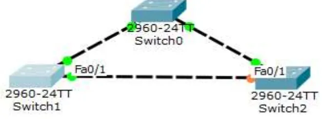
II. SPANNING-TREE PROTOCOL
Spanning-Tree protocol is a layer 2 protocol that runs on bridges and switches. The main purpose of the Spanning –tree protocol is to prevent the loop,[2] when there is an redundant path in the network.
It consist of the root port(switch 0),were all the ports are on and all the ports which are connected to other switch are also on. The other end of the root bridge is designated port, fast Ethernet 0/1 of switch 2 is Non-Designated port(NDP). The NDP is selected on the priority and cost of the bridge. Initially the BRIDGE PACKET DATA UNIT(BPDU) of the switch advertise its information to all other switches, which are connected with it.
III. COMMUNICATION IN A SAME VLAN
As communication in a same VLAN is simple and easier. It is possible to communicate between the host of same VLAN, but it is not possible if the VLANS are different.
Fig. 2: Represents the ports are trunked using the cross-over cable
Here the pc0is in vlan10 interfaced with fast Ethernet 0/1 and the pc3 is vlan20 interfaced with the fast Ethernet 0/13. Similarly the pc2 is vlan10 interfaced with fast Ethernet 0/1 and pc4 is vlan20 interfaced with fast Ethernet 0/13. As the communication within the VLAN does not require an multilayer switch or layer 3 switch or a router.Here it is possible to ping the pc0 with pc3 of same vlan10 or the pc3 with pc4of same vlan20[3].
Fig. 3: Represents the Ping command on the terminal to check the connectivity between any two interfaces
IV. INTER VLAN ROUTING USING THE LAYER-3 SWITCH
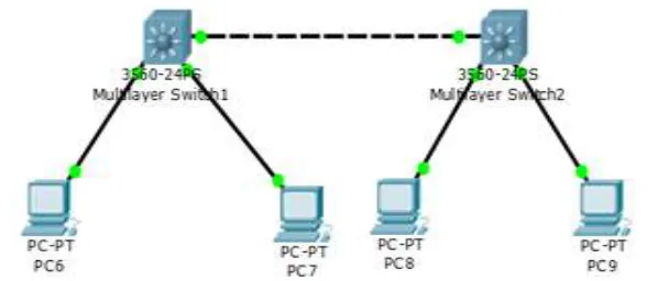
Fig. 4: Represents the each vlan is assigned on the layer-3 switch to communicate different vlans
Here the two multilayer switch 3560 is used, and each of the Multilayer switch is connected with two hosts.[4] The multi Layer switch 1 is connected with the pc6 and pc7 and multilayer switch 2 is connected with pc8 and pc9. It is possible to Ping the same VLAN, to enable the communication between different VLAN in layer 3 switch, the trunk must be enabled between the two multilayer switch
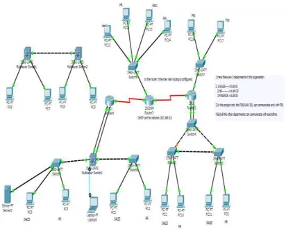
V. INTER-VLAN ROUTING
The inter vlan routing is done using the meathod the ROUTER ON A STICK, in order to establish the communication between the differentVLANS we will have to create the sub interface of fast ethernet interface of the router. We can also apply the encapsulation to the sub interface. In order to apply the VTP apply the domain name and trunk the ports of the switch, trunk ony the ports that are connected to the routers and switches[5]
Fig. 5: Represents the Inter-vlan routing through router
Switch 0: En Config t Vlan 10 Name 10 Vlan 20 Name 20 Exit Int fa0/1
Switchport access vlan 10 Exit
Int fa0/2
Switchport access vlan 20 End
Switcportmode access Switchport access vlan 10 End
Shvlan
Assigning the VLAN to ports En
No shutdown Trunk Ports:
Trunk ports can carry multiple VLANs at a time. A trunk link is 100 or 1000 Mbps point-to-point link between twoswitches[6], between a switch and router, or even between a switch and server, and it carries the traffic of multiple VLANs from 1 to 4094 at a time. This is a great feature because you can actually set ports up to have a server in two separate broadcast domains simultaneously so your users won’t have to cross a layer 3 device (router) to log in and access it. Another advantage is that, trunk links can carry various amounts of[7] VLAN information across the link, but by default, if the links between your switches are not trunked, only information from the configured VLAN will be switched across that link
Static VLANs
Static VLANs are created by network administrator, so these are more secure. Any switch port have assigned to a VLAN will always maintain it unless one change the port assign manually .Static VLAN is easy to set up and any movement in the host required manually update. For a large network which required often more updates of VLAN are not possible statically, we go to dynamic VLANs[8].
Dynamic VLANs
Dynamic VLAN assign VLANs automatically using software, based on hardware address (MAC), protocols and applications. For example, if MAC addresses have been entered into centralized[9] VLAN management application software. If you attached it to an unassigned switch port, the VLAN management database can look up for the hardware address and assign and configure the switch port into the correct VLAN. It is a tuff task to setup database at initial level.
In the dynamic routing protocol , we need to give only the directly connected interface on the CLI(Command line interface) Inter-Switch Link (ISL)
Inter-Switch Link(ISL) is a way of tagging VLAN information onto an Ethernet frame. This tagging information allows VLANs to be multiplexed over a trunk through an external encapsulation method (ISL), which allows the switch to identify the VLAN membership of a frame over the trunked link. By running ISL, you can interconnect multiple switches and still maintain VLAN information as traffic travels between switches on trunk links[10]. ISL functions at layer 2 by encapsulating a data frame with a new header and cyclic redundancy check (CRC). It is used for Fast Ethernet and Gigabit Ethernet links only. ISL routing is versatile and can be used on a switch port, router interface and server interface cards to trunk a server.
IEEE 802.1Q
Created by IEEE as a standardmethod of frame tagging, IEEE 802.1Q inserts a field into the frame to identify the VLAN. If you are Trunking between a Cisco switched link and a different brand of switch, we need to use 802.1Q for the trunk to work
VI. ROUTING PROTOCOLS
RIP: RIP is the one of the oldest Routing information protocol. It uses the distance vector routing protocol. It is the one of the oldest routing information protocol. Each RIP router maintains the routing table, which is the list of the destination networks it knows how to reach, along With the distance to that destination. It sends the packet by the means of distance and direction, and hence it is known as the distance vector routing protocol. RIP is classified by the IETF as an interior gateway protocol. Decides the path metric through the hop count, RIP allows the maximum of 16 hops in a network. Using RIP, each router sends its entire table to its neighbor routers for every 30 second.
RIP has two versions V1and V2. RIP V1 is a classful routing protocol. It supports only the network which are not sub netted. Classful routing protocol do not send their subnet mask information along with their routing updates. It proceeds only throug h limited broadcast IP address 255.255.255.255 to send the packet.[11]
RIP V2 is a hybrid routing protocol. It is similar to the Distance vector routing protocol, but has some of the characteristics of the Link state routing protocol. RIP V2 is the classless routing protocol. It supports the variable length subnet masking and supports the maximum hop count of 15 hops. The authentication is not supported on the both the version of the RIP.
Fig. 5: Represents the RIP version-1 (classful)
Multilayer switch-2(3560) En
Config t Router rip v1
Network 192.168.1.0 255.255.255.0 Network 192.168.20.0 255.255.255.0 Enable
Ip routing Sh ip route
OSPF
Open shortest path first(OSPF) is a Link state routing protocol. It is defined by the cost. The OSPF sends the Link state advertisement to the other routers connected to it, to know the status of nearby router. OSPF is designated by IETF as one of the several interior gate way protocols[13]. It provides the fast convergence. It provides the multicast address. Using OSPF, a router that detects the change in the routing table then it immediately multicast the information to all other OSPF host in the network so they all will have the same routing table information. OSPF send the update information for every 30 seconds. Sometimes due to the equipment failure on the router, the router takes the OSPF routing protocol to find a new path between the end points. Thus minimize the path length and provide the fast convergence[14].
The metric of OSPF is the cost. OSPF cost is given by
OSPF Cost = 100/Bandwidth
In this paper, the OSPF version 2 is used because its supports the IPV4. It is broadly implemented In the enterprise routers. The OSPF V3 works in the same way as the OSPF V2. It is mainly used to support the IPV6.
IEEE RFC 2328 for IPV4 and IEEE RFC 5340.
In OSPF and RIP the neighbor router are dynamically configured. Router 0
En Config t Router ospf 1
Network 192.168.10.0 0 0.0.0.255 area 0 Network 192.168.20.0 0 0.0.0.255 area 0 Network 192.168.30.0 0 0.0.0.255 area 0 Router 1
En Config t Router ospf 1
Network 192.168.30.2 0 0.0.0.255 area 0 Network 192.168.40.0 255.255.255.0 area 1
Fig-9 “O” Represents the OSPF is enabled on the router-1
Router 2 En Config t Router ospf 1
Network 192.168.10.0 0.0.0.255 area 1 Network 192.168.20.0 0.0.0.255 area 1 Network 192.168.40.0 0.0.0.255 area 1
DHCP
Dynamic host configuration protocol(DHCP) is a client or server protocol that automatically provides an Internet protocol host with an IP address and other related configuration such as the subnet mask and gateway.The DHCP is
Fig. 11: Represents the complete configuration
The DHCP works on the DORA process[16] DISCOVER
The client computer sends the DISCOVERY request, asking for its IP information from any listening DHCP servers. OFFER
Any listening DHCP servers will OFFERtheir configuration information to the DHCP client.[17] REQUEST
The client selects the best lese then REQUESTthen lease from the corresponding DHCP server.
VII.CONCLUSION
In the case of single network it is possible to provide privacy using the switch by blocking the other vlans and allowing the particular vlan pass through. Where as in the case of the router, it allow the different vlans of one network to communicate the different vlans of the other network. General purpose of the router is to communicate the different network. In this project we use the access-list that allow only the specified vlan to pass through from one network and reach the specified vlan of the other network and prevent by communicating the other vlan in the network.
ACKNOWLAGMENT
The DHCP server accepts the request from the client and then sends the unicast DHCP ACKNOWLAGMENT message to the client. After receiving the DHCP ACKNOWLAGMENT, the IP address is leased to the DHCP client. A client will usually keep the same address by periodically contacting the DHCP server to renew the lease before the lease expires.
REFERENCE
[1] http://www.cisco.com/en/US/docs/switches/lan/cataly st2950/software/release/12.1_9_ea1/configuration/guide/ swvlan.pdf [2] Forouzan, B. Local Area Networks. New York, NY: McGraw-Hill, 2003.
[3] Sauders, S. Gigabit Ethernet Handbook. New York, NY: McGraw-Hill, 1998. [4] Tanenbaum, A. Computer Networks.Prentice Hall,2003.
[5] Gyan Prakash Pal, Sadhana Pal, “First Boot Of the Router & Storing Its Configuration”, International Journal of Scientific Research Engineering &Technology (IJSRET), Volume 1 Issue1 pp 008-0013 March 2012
[6] Sadhana Pal, Gyan Prakash Pal, “VPN: To Make Private Networks Through Public Networks”, International Journal of Scientific Research Engineering
&Technology (IJSRET), Volume1 Issue3 pp 026-032 June 2012 [7] Keiser, G. Local Area Networks. New York, NY: McGraw-Hill, 2002.
[8] Perlman, R. Interconnection: Bridges, Routers, Switches, and Intemetworking Protocols. Reading, MA: Addison-Wesley, 2000.
[9] Anuj Kumar, Dr. Ashish Chaturvedi “Organization of Energy Efficiency in Wireless Sensor Network” IJSRET Vol 1 Issue 3, June 2012
[10] Sadhana Pal,Gyan Prakash Pal “VPN: To Make Private Networks Through Public Networks” IJSRET Vol 1 Issue 3, June 2012
[11] Tushar Gawande, Prof.N.N Mhala “Network Coding To Improve Performance of AODV Protocol in Wireless Ad-Hoc Network” IJSRET Vol 1 Issue 3, June
2012
[12] Achal Agarwal, Richa Agarwal, Kirtika Goel “A Prescriptive Policy Paper on E-Governance Use of Wireless Technology in Electronic Voting Machine”
IJSRET Vol 1 Issue 3, June 2012
[13] Akhil Kaushik, Hari Om Awashti, Kirtika Goel, Sakshi Goel “Secure Authentication with Encryption Technique for Mobile on Cloud Computing” IJSRET Vol 1 Issue 5, August 2012
[14] Nalini Tyagi, Rahul Gupta, Ruchi Singh “Parent Cluster Head with XML usage in Wireless Network” IJSRET Vol 1 Issue 5, August 2012
[15] Ruchin Mangla, Maninder Singh “MIMOOrthogonal Frequency Division Multiplexing System over Rayleigh Fading Channel with Simulink” IJSRET Vol
1 Issue 5, August 2012