DEPARTEMEN PEKERJAAN UMUM
DIREKTORAT JENDERAL BINA MARGA
DIREKTORAT BINA PROGRAM JALAN
PERATURAN PERENCANAAN
TEKNIK JEMBATAN
LAMPIRAN A
PERSYARATAN TAHAN GEMPA
BRIDGE DESIGN CODE
BRIDGE DESIGN CODE
PERATURAN PERENCANAAN TEKNIK
JEMBATAN
APPENDIX A - DETAILED EARTHQUAKE DESIGN
LAMPIRAN A - PERSYARATAN TAHAN GEMPA
SUMMARY OF CONTENTS
IKHTISAR DAFTAR ISI
TABLE OF CONTENTS ...A - I
DAFTAR ISI ...A - iii
LIST OF TABLES
DAFTAR TABEL ...A - v
LIST OF FIGURES
DAFTAR GAMBAR ...A - v
A.1 INTRODUCTION
PENDAHULUAN...A - 1
A.2 DESIGN PROCEDURE
CARA PERENCANAAN ...A - 7
A.3 GENERAL DESIGN REQUIREMENTS
PERSYARATAN PERENCANAAN UMUM ...A - 17
A.4 DETAILED REQUIREMENTS FOR TYPE A BRIDGES
PERSYARATAN TERPERINCI UNTUK JEMBATAN TIPE A ...A - 26
A.5 DETAILED REQUIREMENTS FOR TYPE B BRIDGES
PERSYARATAN TERPERINCI UNTUK JEMBATAN TIPE B ...A - 37
A.6 DETAILED REQUIREMENTS FOR TYPE C BRIDGES
PERSYARATAN TERPERINCI UNTUK JEMBATAN TIPE C ...A - 39
A.7 SOIL LIQUEFACTION
KEHILANGAN KEKUATAN TANAH - LIQUEFACTION ...A - 41
A.8 BASE ISOLATION AND MECHANICAL DAMPERS
ISOLASI DASAR DAN PEREDAM MEKANIKAL ...A - 44
26 May 1992 Table of Contets
TABLE OF CONTENTS
A.1 INTRODUCTION
A.1.1 SCOPE ... A - 1 A.1.2 APPLICATION ... A - 1 A.1.3 ORGANIZATION OF SECTION ... A - 2 A.1.4 GLOSSARY ... A - 3 A.1.5 SYMBOLS ... A - 3
A.2 DESIGN PROCEDURE
A.2.1 GENERAL ... A - 7 A.2.2 ASSUMPTIONS ... A - 7 A.2.3 PROCEDURE ... A - 8 A.2.4 DEPTH TO FIXITY ... A - 9 A.2.5 MEMBER STRENGTH
A.2.5.1 Nominal Strength ... A - 9 A.2.5.2 Design Strength ... A - 10 A.2.5.3 Overstrength
A.2.6 STRUCTURE DUCTILITY ... A - 11 A.2.7 VERTICAL SEISMIC MOTIONS ... A - 13 A.2.8 DIRECTION OF LOADING ... A - 13 A.2.9 DYNAMIC ANALYSIS
A.2.9.1 General ... A - 13 A.2.9.2 Methods of Analysis
A.2.9.2.1 Elastic Behaviour ... A - 14 A.2.9.2.2 Moderate Inelastic Behaviour ... A - 14 A.2.9.2.3 Inelastic Behaviour ... A - 14 A.2.9.3 Loading Directions ... A -14 A.2.9.4 Input Ground Motions ... A -14 A.2.9.5 Design Forces and Deformations
A.2.9.5.1 Modal Spectral Analysis ... A - 15 A.2.9.5.2 Time-History Analysis ... A - 15 A.2.10 SEISMIC DISPLACEMENTS
A.2.10.1 General ... A - 15 A.2.10.2 Displacement Response ... A - 15
A.3 GENERAL DESIGN REQUIREMENTS
A.3.1 STRUCTURAL INTEGRITY AND PROVISION FOR DISPLACEMENTS
A.3.1.1 Horizontal Linkages ... A - 17 A.3.1.2 Holding-Down Devices ... A - 18 A.3.1.3 Horizontal Clearance ... A - 19 A.3.2 REPAIR CONSIDERATIONS ... A - 20 A.3.3 FREE STANDING RETAINING WALLS
A.3.3.1 General ... A - 20 A.3.3.2 Static Earth Pressure ... A - 20 A.3.3.3 Inertial Force ... A - 20 A.3.3.4 Dynamic Earth Pressure
A.3.3.4.1 Stiff Walls ... A - 21 A.3.3.4.2 Flexible Walls ... A - 21 A.3.3.5 Walls with Footings on Soil ... A - 22 A.3.3.6 Walls on Rock, Piles or Well Foundations ... A - 23 A.3.3.7 Reinforced Earth Walls ... A - 23 A.3.4 ABUTMENT WALLS
A.3.4.1 Non-rigid Connection to Superstructure ... A - 24 A.3.4.2 Rigid Connection to Superstructure ... A - 25
A.4 DETAILED REQUIREMENTS FOR TYPE A BRIDGES
A.4.1 RESTRICTIONS ON LAYOUT ... A - 26 A.4.2 DESIGN OF HINGES IN STRUCTURAL CONCRETE COLUMNS
26 May 1992 Table of Contets
A.4.2.4 Reinforcing Steel ... A - 29 A.4.2.5 Concrete Strength ... A - 29 A.4.2.6 Inner Bound Core ... A - 30 A.4.2.7 Shear ... A - 30 A.4.3 DESIGN OF HINGES IN STRUCTURAL STEEL MEMBERS
A.4.3.1 General ... A - 30 A.4.3.2 Lateral Restraint ... A - 30 A.4.3.3 Shear capacity of Hinge Regions ... A - 30 A.4.3.4 Connection of Hinging Member ... A - 31 A.4.3.5 Moment Capacity of Hinging Sections ... A - 31 A.4.3.6 Materials ... A - 32 A.4.4 DESIGN OF STRUCTURE BETWEEN PLASTIC HINGES
A.4.4.1 General ... A - 32 A.4.4.2 Strength Reduction Factor ... A - 33 A.4.4.3 Shear ... A - 33 A.4.4.4 Connection of Hinges ... A - 34 A.4.4.5 Buckling of Columns ... A - 34 A.4.4.6 Instability Effects ... A - 34 A.4.4.7 Joints ... A - 35 A.4.4.8 Special Provisions for Structural Concrete
A.4.4.8.1 Shear ... A - 35 A.4.4.8.2 Splices in longitudinal Reinforcing ... A - 35 A.4.4.9 Special Provisions for Structural Steel
A.4.4.9.1 Column Splices ... A - 36 A.4.4.9.2 Connections ... A - 36 A.4.5 DESIGN OF ARTICULATIONS ... A - 36
A.5 DETAILED REQUIREMENTS FOR TYPE B BRIDGES
A.5.1 GENERAL ... A - 37 A.5.2 DESIGN OF ARTICULATIONS
A.5.2.1 General ... A - 37 A.5.2.2 Design of Linkages at Abutments ... A - 37 A.5.2.3 Design of Linkages at Expansion Joints ... A - 37
A.6 DETAILED REQUIREMENTS FOR TYPE C BRIDGES
A.6.1 RESTRICTIONS ON LAYOUT ... A - 39 A.6.2 STRUCTURAL TYPE FACTOR ... A - 39 A.6.3 FOUNDATIONS ... A - 40 A.6.4 INTEGRITY OF CONNECTIONS ... A - 40
A.7 SOIL LIQUEFACTION
A.7.1 GENERAL ... A - 41 A.7.2 LIQUEFACTION POTENTIAL
A.7.2.1 Simplified Method Based on Chinese Building Code Data ... A - 41 A.7.2.2 Method Based on Cyclic Stress Ratio Analysis ... A - 43
A.8 BASE ISOLATION AND MECHANICAL DAMPERS
A.8.1 GENERAL ... A - 44 A.8.2 BASE ISOLATION ... A - 44 A.8.3 MECHANICAL DAMPERS ... A - 45 A.8.4 APPLICATION TO BRIDGES ... A - 45 A.8.5 MINIMUM DESIGN REQUIREMENTS FOR BRIDGES INCORPORATING MECHANICAL
ENERGY DISSIPATORS ... A - 46
REFERENCES
26 May 1992 Table of Contets
DAFTAR ISI
A.1 PENDAHULUAN
A.1.1 RUANG LINGKUP ...A - 1 A.1.2 PENGGUNAAN ...A - 1 A.1.3 SUSUNAN BAGIAN PENJELASAN ...A - 2 A.1.4 ISTILAH ...A - 3 A.1.5 NOTASI ...A - 3
A.2 CARA PERENCANAAN
A.2.1 UMUM ...A - 7 A.2.2 ANGGAPAN-ANGGAPAN ...A - 7 A.2.3 TAHAPAN ...A - 8 A.2.4 KEDALAMAN JEPIT ...A - 9 A.2.5 KEKUATAN KOMPONEN
A.2.5.1 Kekuatan Nominal ...A - 9 A.2.5.2 Kekuatan Rencana ...A - 10 A.2.5.3 Kekuatan Lebih ...A - 11 A.2.6 DAKTILITAS STRUKTUR ...A - 11 A.2.7 GERAKAN SEISMIK VERTIKAL ...A - 13 A.2.8 ARAH PEMBEBANAN ...A - 13 A.2.9 ANALISA DINAMIK
A.2.9.1 Umum ...A -13 A.2.9.2 Cara Analisa
A.2.9.2.1 Perilaku Elastis ...A-14 A.2.9.2.2 Perilaku Moderat Tidak Elastis ...A-14 A.2.9.2.3 Perilaku Tidak Elastis ...A-14 A.2.9.3 Arah Pembebanan ...A-14 A.2.9.4 Masukan Gerakan Tanah ...A-14 A.2.9.5 Gaya Dan Deformasi Rencana
A.2.9.5.1 Analisa Modal Spektral ...A-15 A.2.9.5.2 Analisa Riwayat Waktu (Time-history) ...A-15 A.2.10 SIMPANGAN SEISMIK
A.2.10.1 Umum ...A-15 A.2.10.2 Simpangan Respons ...A-15
A.3 PERSYARATAN PERENCANAAN UMUM
A.3.1 INTEGRITAS STRUKTURAL DAN PERLENGKAPAN TERHADAP SIMPANGAN
A.3.1.1 Hubungan Horisontal ...A - 17 A.3.1.2 Perlengkapan Penahan Vertikal ...A - 18 A.3.1.3 Jarak Bebas Horisontal ...A - 19 A.3.2 PERTIMBANGAN PERBAIKAN ...A - 20 A.3.3 TEMBOK PENAHAN YANG BERDIRI BEBAS
A.3.3.1 Umum ...A - 20 A.3.3.2 Tekanan Tanah Statik ...A - 20 A.3.3.3 Gaya Inersia ...A - 20 A.3.3.4 Tekanan Tanah Dinamik
A.3.3.4.1 Tembok Kaku ...A - 21 A.3.3.4.2 Tembok Fleksibel ...A - 21 A.3.3.5 Tembok dengan Pondasi Diatas Tanah ...A - 22 A.3.3.6 Tembok pada Pondasi Batuan, Tang atau Sumuran ...A - 23 A.3.3.7 Tembok Tanah Bertulang ...A - 23 A.3.4 TEMBOK PANGKAL
A.3.4.1 Hubungan Tidak Kaku Terhadap Bangunan Atas ...A - 24 A.3.4.2 Hubungan Kaku Terhadap Bangunan Atas ...A - 25
A.4 PERSYARATAN TERPERINCI UNTUK JEMBATAN TIPE A
A.4.1 PEMBATASAN PADA DENAH ...A - 26 A.4.2 PERENCANAAN SENDI DALAM KOLOM BETON STRUKTURAL
26 May 1992 Table of Contets
A.4.2.4 Baja Tulangan ... A - 29 A.4.2.5 Kekuatan Beton ... A - 29 A.4.2.6 Inti dalam yang Terikat ... A - 30 A.4.2.7 Geser ... A - 30 A.4.3 PERENCANAAN SENDI DALAM KOMPONEN STRUKTURAL BAJA
A.4.3.1 Umum ... A - 30 A.4.3.2 Ketahanan Lateral ... A - 30 A.4.3.3 Kapasitas Geser dari Daerah Sendi ... A - 30 A.4.3.4 Hubungan Dari Komponen Bersendi ... A - 31 A.4.3.5 Kapasitas Momen dari Bagian Bersendi ... A - 31 A.4.3.6 Bahan-bahan ... A - 32 A.4.4 PERENCANAAN STRUKTUR ANTARA SENDI PLASTIS
A.4.4.1 Umum ... A - 32 A.4.4.2 Faktor Reduksi Kekuatan ... A - 33 A.4.4.3 Geser ... A - 33 A.4.4.4 Hubungan dari Sendi-sendi ... A - 34 A.4.4.5 Tekuk dari Kolom-kolom ... A - 34 A.4.4.6 Pengaruh Ketidak Stabilan ... A - 34 A.4.4.7 Sambungan-sambungan ... A - 35 A.4.4.8 Pengadaan Khusus Untuk Beton Struktural
A.4.4.8.1 Geser ... A - 35 A.4.4.8.2 Sambungan dalam Tulangan Memanjang ... A - 35 A.4.4.9 Pengadaan Khusus untuk Baja Struktural
A.4.4.9.1 Sambungan Kolom ... A - 36 A.4.4.9.2 Hubungan-hubungan ... A - 36 A.4.5 RENCANA HUBUNGAN ARTIKULASI ... A - 36
A.5 PERSYARATAN TERPERINCI UNTUK JEMBATAN TIPE B
A.5.1 UMUM ... A - 37 A.5.2 RENCANA HUBUNGAN ARTIKULASI
A.5.2.1 Umum ... A - 37 A.5.2.2 Rencana Hubungan pada Pangkal Jembatan ... A - 37 A.5.2.3 Rencana Hubungan pada Sambungan Dilatasi ... A – 37
A.6 PERSYARATAN TERPERINCI UNTUK JEMBATAN TIPE C
A.6.1 PEMBATASAN DENAH ... A - 39 A.6.2 FAKTOR TIPE STRUKTURAL ... A - 39 A.6.3 PONDASI ... A - 40 A.6.4 INTEGRITAS DARI HUBUNGAN-HUBUNGAN ... A - 40
A.7 KEHILANGAN KEKUATAN TANAH - LIQUEFACTION
A.7.1 UMUM ... A - 41 A.7.2 POTENSIAL LIQUEFACTION
A.7.2.1 Cara Sederhana Berdasarkan Data Tata Cara Bangunan di China ... A - 41 A.7.2.2 Cara Berdasarkan Analisa Perbandingan Tegangan Berulang ... A – 43
A.8 ISOLASI DASAR DAN PEREDAM MEKANIKAL
A.8.1 UMUM ... A - 44 A.8.2 ISOLASIDASAR ... A - 44 A.8.3 PEREDAM MEKANIKAL ... A - 45 A.8.4 PENERAPAN PADA JEMBATAN ... A - 45 A.8.5 PERSYARATAN MINIMUM UNTUK RENCANA JEMBATAN DENGAN PERLENGKAPAN
PENYERAPAN ENERGI MEKANIKAL (DISSIPATOR) ... A - 46
PUSTAKA
26 May 1992 Table of Contets
LIST OF TABLES DAFTAR TABEL
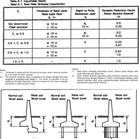
Table A.1 Tabel A.1
Liquefiable Sands
Pasir Pbka Terhadap Liquefaction ...A - 10
LIST OF FIGURES DAFTAR GAMBAR
Figure A.1 Gambar A.1
Depth to Fixity
Kedalaman Jepit ...A -10
Figure A.2 Gambar A.2
Ductility
Daktilitas ... A - 12
Figure A.3 Gambar A.3
Link Slab
Pelat Hubungan Sendi ...A - 17
Figure A.4 Gambar A.4
Lateral Restraints at Abutments
Penahan Lateral pada Pangkal Jembatan ...A - 18
Figure A.5 Gambar A.5
Overlap Distance
Jarak Bebas ...A - 19
Figure A.6 Gambar A. 6
Stiff Wall Pressure
Tekanan pada Tembok Kaku ...A - 21
Figure A.7 Gambar A. 7
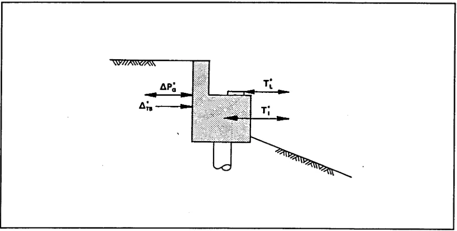
Forces on Abutment Walls
Gaya-gaya Tembok Pangkal ... A - 24
Figure A.8 Gambar A. 8
Typical Details of Binding Reinforcement
Tipikal Detail Tulangan Pbngikat ...A - 29
Figure A.9 Gambar A.9
Shear in Columns
Geser dalam Kolom-kolom ... A - 34
Figure A.10 Gambar A.10
Typical Expansion Joint Details
Tipikal Detail Sambungan Dilatasi ...A - 38
Figure A.1 1 Gam bar A. 11
Overburden Correction CN
Koreksi CN Terhadap Kedalaman ...A - 43
Figure A.12 Gambar A. 12
Effect of Flexible Mountings
APPENDIX A
DETAILED EARTHQUAKE
DESIGN
A.1 INTRODUCTION
A.1.1
SCOPE
This Section gives detailed requirements for bridges subject to earthquakes. These requirements are in addition to the other Sections of the Code and shall be read in conjunction with them.
The requirements of this Section represent current standards of good practice. They are not mandatory, but should be followed wherever possible to ensure that a bridge has the best chance of survival in the event of a major earthquake.
A.1.2
APPLICATION
This Section applies to road bridges in all parts of Indonesia, except for special structures.
The design of special structures requires the use of analysis techniques that are beyond the scope of this Section, although some general guidelines for dynamic analysis are given. Such techniques should only be used under the guidance of a Design Engineer with extensive experience in seismic design of bridges.
Special structures are bridges which meet any of the following four sets of conditions:
i. Special Structural Types:
x cable supported bridges;
x arch bridges;
x bridges using special energy dissipators; ii. Bridges with Extreme Geometry:
x bridges with tall piers such that the mass of a pier is greater than 20 % of the mass of the portion of the superstructure that contributes to the inertia load on the pier;
x bridges where the stiffness of the piers differs by more than the amount recommended in Article A.4.1;
x bridges with spans greater than 200 m;
LAMPIRAN A
PERSYARATAN TAHAN GEMPA
A.1
PENDAHULUAN
A.1.1
RUANG LINGKUP
Bagian ini memberikan penjelasan persyaratan jembatan terhadap gempa. Persyaratan ini melengkapi bagian-bagian lain dari Tata Cara dan harus dibaca secara berkaitan satu dengan lainnya.
Persyaratan dalam Bagian ini mewakili standar pelaksanaan yang baik dan berlaku. Syarat-syarat tersebut tidak mutlak, tetapi sedapat mungkin harus diikuti untuk menjamin bahwa suatu jembatan mempunyal kemungkinan terbaik untuk selamat dalam kejadian gempa besar.
A.1.2
PENGGUNAAN
Bagian ini digunakan untuk Jembatan Jalan Raya di seluruh wilayah Indonesia, kecuali untuk struktur khusus.
Perencanaan struktur khusus menuntut penggunaan tehnik analisa yang diluar lingkup bagian ini, walaupun telah diberikan beberapa pedoman umum untuk analisa dinamik. Tehnik demikian hanya boleh digunakan dibawah pengawasan Ahli Tehnik Perencana yang cukup berpengalaman dalam perencanaan seismik jembatan.
Struktur khusus adalah jembatan yang memenuhi salah satu dari empat kelompok kondisi berikut:
i. Tipe Struktur khusus:
x jembatan yang didukung oleh kabel
x jembatan lengkung
x jembatan yang menggunakan perlengkapan khusus untuk menyerap (dissipator) energi.
ii. Jembatan dengan geometrik khusus:
x jembatan dengan pilar tinggi sedemikian sehingga massa pilar adalah lebih besar dari 20 % massa bagian bangunan atas yang memberikan beban inersia pada pilar;
x jembatan dengan kekakuan pilar-pilar yang berbeda dengan nilai yang dianjurkan dalam persyaratan Artikel A.4.1;
x highly skewed bridges;
x bridges with large horizontal curvatures;
x piers in deep water.
iii. Bridges in Difficult Locations:
x sites across or near active faults;
x sites on or near potentially unstable slopes;
x liquefiable foundations;
x very soft foundations.
iv. Very Important Bridges:
x bridges with a high economic importance due to high construction cost or consequences of failure.
A.1.3
ORGANIZATION OF SECTION
This Section consists of guidelines and recommendations only. Consequently, all necessary explanation is included in the text and there is no corresponding section in the Commentary.
References are provided wherever possible. However, earthquake engineering is a very active research area and the Design Engineer is advised to seek out the most up-to-date information available for the design of complex bridges.
This Section is organized as follows:
Sub-section A.2 sets out the general design
procedures. Parameters used in seismic analysis of bridges are defined and the procedures for computing then are given. The principles of over strength design are explained. Guidelines are given for dynamic analysis.
Sub-section A.3 sets out the general design
requirements for siesmic restraints and connectivity for a bridge. Methods are given for computation of dynamic loads on retaining walls and abutments.
Sub-section A.4 sets out the detailed requirements
for fully ductile monolithic bridges (Type A). This covers design of concrete and steel hinge regions and the overstrength requirements for the members linking plastic hinges.
Sub-section A.5 sets out the detailed requirements
for fully ductile articulated bridges (Type B). Specific recommendations are given for the detailing
x jembatan dengan kemiringan sudut yang besar;
x jembatan dengan lengkung horisontal yang besar;
x pilar diperairan dalam.
iii. Jembatan pada lokasi rumit :
x lapangan melintasi atau dekat retakan aktip;
x lapangan pada atau dekat lereng yang potensial tidak stabil;
x pondasi yang dapat mengalami liquefaction -kehilangan kekuatan tanah;
x pondasi pada tanah sangat lunak.
iv. Jembatan sangat panting:
x jembatan dengan kepentingan segi ekonomi karena biaya konstruksi sangat besar atau akibat keruntuhan yang fatal.
A.1.3
SUSUNAN BAGIAN
PENJELASAN
Bagian ini terdiri dari pedoman dan anjuran persyaratan saja. Sehingga semua penjelasan yang diperlukan telah dicakup didalam uraian dan tidak terdapat artikel yang berkaitan dalam penjelasan ini.
Pustaka telah diberikan sebanyak mungkin. Bagaimanapun, tehnik gempa adalah suatu bidang penelitian yang aktip dan dianjurkan agar Akhli Tehnik Perencana berusaha mencari informasi terbaru yang tersedia untuk perencanaan jembatan dengan struktur rumit.
Susunan bagian ini adalah sebagai berikut:
Bab A.2 menetapkan langkah perencanaan secara
umum. Parameter yang digunakan dalam analisa seismik jembatan ditetapkan dan cara perhitungan kemudian diberikan. Dasar-dasar perencanaan "kekuatan lebih" dijelaskan. Pedoman untuk analisa dinamik diberikan.
Bab A.3 menetapkan persyaratan perencanaan
secara umum untuk penahan gempa dan hubungannya untuk suatu jembatan. Cara-cara diberikan untuk perhitungan beban dinamik pada tembok penahan dan pangkal jembatan.
Bab A.4 menetapkan persyaratan terperinci untuk
jembatan monolitik dengan daktilitas penuh (Tipe A). Ini mencakup perencanaan daerah sendi plastis pada beton dan baja, dan persyaratan "kekuatan lebih" untuk bagian-bagian penghubung sendi-sendi plastis.
Bab A.5 menetapkan persyaratan terperinci untuk
o
f linkages between the bridge elements and for provision of structural integrity across joints.Sub-section A.6 sets out the detailed requirements
for non-ductile bridges (Type C).
Subsection A.7 sets out guidelines for assessing the
liquefaction potential of loose sandy soils. Two methods are given, both based on empirical studies.
Sub-section A.8 provides information on mechanical
devices that can modify the siesmic response of a bridge. This Sub-section is informative only and is not sufficient by itself for the selection and design of such devices.
A.1.4
GLOSSARY
Design Bending Strength is the Nominal Bending
Strength of a member factored by the appropriate Strength Reduction Factor from Section 6 or 7.
Ductility is the ratio of the maximum plastic
displacement of a member (or structure) to the displacement at first yield. Ductility is usually restricted by the requirement that it remain constant over several cycles of loading.
Ductility demand is the ductility needed by a structure to resist the design earthquake loading combination.
Nominal Bending Strength is the ultimate nominal bending strength of a member computed in accordance with Section 6 or 7.
Overstrengthis the Nominal Bending Strength factored
by the Overstrength Factor.
Overstrength Factor is the ratio of the probable maximum bending strength of a member to its Nominal Bending Strength.
A.1.5
SYMBOLS
Ag gross cross-section area of a reinforced concrete
column (m2), see clause A.4.2.3
Ac area of the core of a spirally reinforced concrete
column (m2), see clause A.4.2.3
As gross cross section area of a steel section (mm'),
see clause A.4.3.3
Ash total area of confining reinforcement (mm'), see
clause A.4.2.3
khusus diberikan untuk detail hubungan antara elemen-elemen jembatan dan untuk mengadakan kesatuan struktural pada hubungan/sambungan.
Bab A.6 menetapkan persyaratan terperinci untuk
jembatan tidak daktail (Tipe C).
Bab A.7 menetapkan pedoman untuk pendekatan
potensial liquefaction, pada tanah pasir lepas. Diberikan dua cara, keduanya berdasarkan penelitian empirik.
Bab A.8 memberikan keterangan untuk perlengkapan
mekanikal yang dapat mememperbaiki respons seismik jembatan. Bab ini hanya bersifat informatif dan tidak mencukupi dalam pemilihan dan perencanaan perlengkapan tersebut.
A.1.4
ISTILAH
Kekuatan Lentur Rencana adalah kekuatan lentur nominal dari suatu komponen yang diberi factor sesuai Faktor Reduksi kekuatan dari Bagian 6 atau 7.
Daktilitas adalah perbandingan antara simpangan plastis maksimum dari suatu komponen (atau struktur) dengan simpangan pada pelelehan pertama. Daktilitas umumnya dibatasi oleh persyaratan bahwa dapat bertahan pada beberapa pembebanan berulang.
Persyaratan Daktilitas adalah daktilitas yang
diperlukan oleh suatu struktur untuk menahan kombinasi pembebanan Gempa Rencana.
Kekuatan Lentur Nominal adalah kekuatan lentur nominal ultimate-putus dari suatu komponen yang diperhitungkan sesuai Bagian 6 atau 7.
Kekuatan lebih adalah Kekuatan Lentur Nominal yang diberi faktor sesuai faktor kekuatan lebih (overstrength).
Faktor Kekuatan Lebih adalah perbandingan antara kekuatan lentur maksimum mungkin dari suatu komponen dengan kekuatan lentur nominalnya.
A.1.5
NOTASI
Ag luas penampang bruto dari kolom beton bertulang
(m2), lihat pasal A.4.2.3.
Ac luas inti dari kolom beton bertulang spiral (m2),
lihat pasal A.4.2.3.
As luas penampang bruto dari penampang baja
(mm'), lihat pasal A.4.3.3.
Ash jumlah luas tulangan pengikat (mm2), lihat pasal
Aw area of the web of a steel section (mm2), see
clause A.4.3.3
CN factor for normalising standard penetration
resistance defined in clause A.7.2.1
Cu undrained cohesion of a soil (kPa)
D50 grain size corresponding to 50 % fraction by weight
of a soil (mm), see clause A.7.2.2
d diameter of a reinforcing bar (mm)
df depth to fixity (m) defined in Article A.2.4
do minimum overlap between the end of a girder and
the edge of a support (m) defined in clause A.3.1.3
ds depth to sand layer (m), see clauses A.7.2.1 and
A.7.2.2
dw depth to water table (m), see clause A.7.2.1
E modulus of elasticity (MPa)
FL liquefaction resistance factor defined in clause
A.7.2.2
fa fraction of the design earthquake acceleration
defined in clause A.3.3.5
f’c characteristic concrete cylinder strength at 28 days
(MPa)
fy characteristic steel yield strength (MPa)
fyh yield strength of binding reinforcement (MPa), see
clause A.4.2.3
g acceleration due to gravity = 9.80 mV
H height of retaining wall or abutment (m)
hc dimension of concrete core to outside of rectangular hoop reinforcement (mm), see clause A.4.2.3
I second moment of area of a section (elastic)
Kh coefficient of horizontal seismic loading (ref.
Section 2)
KR strength reduction factor (ref. Sections 6 and 7)
K° overstrength factor defined in clause A.2.5.3
K coefficient of active earth pressure "
a
Aw luas badan dari penampang baja (mm'), lihat
pasal A.4.3.3.
CN faktor untuk normalisasi ketahanan penetrasi
standar ditentukan dalam pasal A.7.2.1.
Cu kohesi undrained tanah (kPa)
D50 ukuran butir sehubungan fraksi 50 % berat tanah
(mm), lihat pasal A.7.2.2.
d diameter batang tulangan (mm)
df kedalaman jepit (m) ditentukan dalam artikel
A.2.4.
do sambungan lebih (overlap) minimal antara ujung
gelagar dan tepi perletakan (m) ditentukan dalam pasal A.3.1.3.
ds kedalaman lapis pasir (m), lihat pasal A.7.2.1 dan
A.7.2.2.
dw kedalaman muka air (m), lihat pasal A.7.2.1. E
E Modulus Elastisitas
FL Faktor ketahanan kekuatan pasir (liquefaction)
ditentukan dalam pasal A.7.2.2.
fa fraksi percepatan gempa rencana ditentukan
dalam pasal A.3.3.5.
f’c kekuatan karakteristik beton silinder pada 28 hari
(MPa)
fy kekuatan karakteristik leleh baja (MPa)
fyh kekuatan leleh dari tulangan pengikat (MPa), lihat
pasal A.4.2.3.
g percepatan gravitasi = 9.80 m/detik
H tinggi tembok penahan atau pangkal jembatan (m)
hc dimensi inti beton terhadap tepi luar dari tulangan sengkang persegi (mm), lihat pasal A.4.2.3
I Momen kedua dari luas penampang (elastis)
Kh Koefisien pembebanan seismik horisontal (lihat
Bagian 2)
KR faktor Reduksi Kekuatan (lihat Bagian 6 atau 7)
K° faktor kekuatan lebih (overstrength) ditentukan dalam pasal A.2.5.3.
K Koefisien tekanan tanah aktip "
K"aG coefficient of dynamic active earth pressure
defined in clause A.3.3.4
L length of a column (m)
M nominal bending strength of a member (kN m)
MM modified Mercalli earthquake intensity, see clause A.7.2.1
M” design bending strength of a member (kN m), see clause A.2.5.2
M° overstrength bending strength of a member (kN m) defined in clause A.2.5.3
N standard penetration resistance (number of blows per 300 mm)
N1 normalised standard penetration resistance, see clause A.7.2.1
NM function of earthquake shaking intensity defined in clause A.7.2.1
NC limit of standard penetration resistence corresponding to onset of liquefaction defined in clause A.7.2.1
P axial load in a column at the overstrength condition (kN), see clause A.4.3.3
o a
RD a factor defined in clause A.7.2.2
RL resistance of soil elements to dynamic loading defined in clause A.7.2.2
r radius of gyration of a column section (m)
rc cyclic shear stress ratio defined in clause A.7.2.2
rd stress reduction factor defined in clause A.7.2.2
S span length (m)
sh centre to centre spacing of hoop and tie sets (mm),
see clause A.4.2.3
T period of the fundamental frequency of vibration of the structure in bending (sec)
T horizontal earthquake force on an abutment due to its own inertia (kN), see clause A.3.4.1
"
l
T horizontal earthquake force on an abutment due to the inertia of the superstructure (kN), see clause A.3.4.1
"
L
K"G Koefisien tekanan tanah aktip dinamik ditentukan dalam pasal A.3.3.4
a
L panjang kolom (m)
M kekuatan lentur nominal dari suatu komponen (kNm)
MM Intensitas gempa Modified Mercalli, lihat pasal A.7.2.1
M” kekuatan lentur Rencana dari suatu komponen (KNm), lihat pasal A.2.5.2.
M° kekuatan lentur lebih dari suatu komponen (kNm), ditentukan dalam pasal A.2.5.3
N ketahanan penetrasi standar - SPT (jumlah pukulan tiap 300 mm)
N1 ketahanan penetrasi standar yang dinormalisasi, lihat pasal A.7.2.1
NM fungsi intensitas goncangan gempa ditentukan dalam pasal A.7.2.1.
NC batas ketahanan penetrasi standar sehubungan terjadinya kehilangan kekuatan pasir (liquefaction) ditentukan dalam pasal A.7.2.1
P beban aksial dalam kolom pada keadaan kekuatan lebih (kN), lihat pasal A.4.3.3
o a
RD faktor yang ditentukan dalam pasal A.7.2.1
RL ketahanan elemen tanah terhadap pembebanandinamik ditentukan dalam pasal A.7.2.2
r jari-jari girasi dari penampang kolom (m)
r perbandingan tegangan geser berulang ditentukan dalam pasal A.7.2.2
c
r faktor Reduksi tegangan ditentukan dalam pasal A.7.2.2
d
S panjang bentang (m)
s jarak pusat ke pusat dari susunan tulangan melingkar dan pengikat, (mm), lihat pasal A.4.2.3
h
T periode-waktu getar dari frekuensi fundamental alami struktur dalam lentur (detik).
T gaya gempa horisontal pada pangkal jembatan akibat inersia sendiri (kN), lihat pasal A.3.4.1 "
l
T gaya gempa horisontal pada pangkal jembatan akibat inersia bangunan atas (kN), lihat pasal A.3.4.1
"
V shear induced by overstrength plastic hinging (kN), see clause A.4.3.3
o w
ws unit weight of soil (Mn) a slope of backfill
D back slope of a wall
E
black slope of wall'
h maximum estimated seismic deflection of thecentre of mass of a structure (mm), see clauses A.2.10.2 and A.3.3.5
'
E deflection of a member or structure at limit of elastic response (first yield) (mm), see Article A.2.6'
P available plastic deflection of a member orstructure beyond the elastic limit (mm), see Article A.2.6
'
Pg design dynamic earth pressure (kPa) defined inclause A.3.3.4
'
P"gGincremental coefficient of dynamic earthpressure (kPa) defined in clause A.3.3.4
G
’ design angle of soil/wall frictionT
earthquake coefficient used for dynamic earth pressure defined in clause A.3.3.4V
o total overburden pressure on a sand layer (kPa), see clause A.7.2.2V
'o effective overburden pressure on a sand layer
(kPa), See clause A.7.2.2
W
cyclic shear stress (kPa)I
"design angle of soil friction
P
member or overall structure ductility defined in Article A.2.6V geser yang timbul oleh kekuatan lebih dari sendi plastis (kN), lihat pasal A.4.3.3
o w
ws satuan berat isi tanah (kN/m3)
D sudut kemiringan tanah urug
E
sudut kemiringan bagian belakang tembok'
h perkiraan lendutan seismik maksimum daripusat massa suatu struktur (mm), lihat pasal A.2.10.2 dan A.3.3.5
l
'
E lendutan suatu komponen atau struktur pada batas respons elastis (pelelehan pertama) (mm), lihat artikel A.2.6'
P lendutan plastis yang tersedia pada suatukomponen atau struktur dibawah batas elastis (mm), lihat artikel A.2.6
'
Pg tekanan tanah dinamik Rencana (kPa)ditentukan dalam pasal A.3.3.4
'
P"gGkoefisien tambahan pada tekanan tanahdinamik (kPa) ditentukan pasal A.3.3.4
G
’ sudut geser Rencana dari tanah/tembokT
koefisien gempa yang digunakan untuk tekanan tanah dinamik ditentukan dalam pasal A.3.3.4V
o jumlah tekanan diatas suatu lapis pasir (kPa), lihat pasal A.7.2.2V
'o jumlah tekanan efektip diatas suatu lapis pasir
(kPa, lihat pasePA.7.2.2)
W
tegangan geser berulang (kPa)I
"sudut geser tanah rencana
A.2
DESIGN PROCEDURE
A.2.1
GENERAL
Earthquake design id a compromise between the need for bridged to survive earthquakes and the high cost of providing the required strength. The design levels chosen for earthquake loads in this Code are such a compromise. These loads represent an earthquake level which id likely to be exceeded a few timed during the life of a bridge, do that the probability of damage to the bridge id significant. However, if the bridge id detailed carefully the damage will be limited in extent and repairs will be relatively easy and inexpensive.
The design procedures specified in this Sub-section endure that earthquake damage will be limited to predetermined locations. It id important to understand that these procedures involve the computation of a member's maximum likely strength ad well ad its minimum likely strength. When a plastic hinge forms in a member, the sections of the member remote from the hinging zone must be strong enough to withstand the forced generated if the plastic bending moment id bigger than expected. Otherwise, during an earthquake larger than the design earthquake, the member may fail catastrophically in shear instead of forming predictable hinged. (Reference C)
A.2.2
ASSUMPTIONS
i. It id assumed that the behaviour of the structure under the design earthquake loading combinations can be approximated by an elastic analysis. The elastic stiffness of structural concrete members should, therefore, be based on the cracked section moment of inertia computed ad follows (Reference C):
x for members intended to form plastic hinged, use the El value corresponding to first yield of the reinforcement;
x for members intended to remain elastic, use the average of the uncracked section El and the value calculated in the previous paragraph for first yield.
ii. The ductility demand for the overall structure under the design earthquake loading combinations does not exceed six;
iii. The subsurface conditions at the site are adequately taken into account in the selection of the earthquake response coefficient in Section 2.
A.2
CARA PERENCANAAN
A.2.1
UMUM
Perencanaan tahan gempa adalah suatu kesepakatan antara keperluan agar jembatan selamat pada gempa dan biaya tinggi untuk mengadakan kekuatan yang disyaratkan. Tingkat perencanaan yang dipilih untuk beban gempa dalam Tata Cara ini mencerminkan kesepakatan tersebut. Beban-beban ini mewakili suatu tingkat gempa yang akan dapat dilampaui beberapa kali selama umur jembatan, sehingga kemungkinan kerusakan jembatan menjadi penting. Bagaimanapun, bila jembatan dilaksanakan dengan detail cukup baik, luas kerusakan akan dapat dibatasi dan perbaikan akan menjadi relatip mudah dan murah.
Tahap cara perencanaan yang dispesifikasi dalam Bab ini, menjamin bahwa kerusakan akibat gempa akan dibatasi pada lokasi-lokasi tertentu. Penting untuk diadakan pengertian bahwa tahap-tahap tersebut mencakup perhitungan kekuatan maksimum komponen dan juga kekuatan minimumnya yang diharapkan. Bila terjadi pembentukan sendi plastis dalam suatu komponen, bagian komponen yang berada diluar daerah sendi plastis harus cukup kuat untuk menahan gaya-gaya yang dihasilkan bila momen lentur pladtid adalah lebih bedar dari yang diharapkan. Bila tidak, maka pada suatu gempa lebih besar dari gempa rencana, komponen tersebut dapat runtuh fatal akibat geser karena tidak terbentuknya sendi-sendi yang diharapkann (Pustaka C).
A.2.2
ANGGAPAN ANGGAPAN
i. Dianggap bahwa perilaku struktur pada kombinasi pembebanan gempa rencana dapat diperkirakan berdasarkan analisa elastis. Kekakuan elastis dari komponen beton struktural, dengan demikian harusd berdasarkan momen inersia penampang retak yang diperhitungkan sebagai berikut (Pustaka C).
x untuk komponen yang akan membentuk sendi plastis, gunakan nilai El seduai dengan pelelehan pertama dari tulangan.
x untuk komponen yang akan tetap elastis, gunakan rata-rata dari nilai El untuk penampang utuh dan nilai perhitungan dalam butir sebelumnya untuk pelelehan pertama.
ii. Persyaratan daktilitas untuk seluruh struktur pada kombinasi pembebanan gempa rencana, tidak melebihi nilai enam.
2.3
PROCEDURE
For ductile and partially ductile structures, in which a plastic hinging mechanism is likely to develop, the design procedure should comprise two stages (based on reference C):
i. Design plastic hinge sections to have the minimum required flexural strengths:
(a) decide structural form and choose desired locations of plastic hinges to allow a plastic mechanism to develop;
(b) carry out an elastic analysis under the various earthquake loading combinations specified in Section 2;
(c) determine the minimum bending strengths required for plastic hinges. Design these sections to have sufficient Design Bending Strength.
ii. Design all sections other than the plastic hinges for shear and bending. Design plastic hinges for shear:
(a) compute overstrength bending strength of the plastic hinges designed in accordance with (I) above;
(b) analyze structure assuming that all plastic hinges have developed their overstrength bending strengths;
(c) determine shear and bending strengths required for all sections other than the plastic hinges, and design sections accordingly;
(d) design plastic hinges for shear.
In partially ductile structures, the hinging zones should be designed as for fully ductile structures. In addition, those earthquake-resisting elements that are designed to remain ductile should be designed for the forces produced by a total deformation equal to the appropriate horizontal limit displacement given in Article A.2.10.
Some structures use methods other than plastic hinges for absorbing the energy generated by earthquake motions. For these structures, the design procedure should be as follows:
(a) determine the forces generated by the. energy absorbing dampers using the earthquake loading combinations specified in Section 2;
(b) design the connections to these dampers, and associated members, to have a strength
A.2.3
TAHAPAN
Untuk struktur daktail dan daktail parsial, padamana mekanisme sendi plastis dapat berkembang, cara perencanaan harus terdiri dari 2 tahap (berdasarkan Pustaka C):
i. Rencana penampang sendi plastis sehingga mempunyai kekuatan lentur minimum yang diperlukan:
(a) tentukan bentuk struktur dan pilih lokasi sendi plastis yang diinginkan untuk mengijinkan perkembangan mekanisme plastis.
(b) laksanakan suatu analisa elastis pada berbagai kombinasi pembebanan gempa yang dispesifikasi dalam Bagian 2.
(c) tentukan kekuatan lentur minimum yang diperlukan untuk sendi plastis. Rencanakan penampang tersebut untuk mempunyai kekuatan lentur rencana yang cukup.
ii. Rencanakan semua penampang selain sendi plastis terhadap geser dan lentur. Rencanakan sendi plastis terhadap geser:
(a) hitung kekuatan lentur lebih dari sendi plastis yang - direncanakan sesuai butir (I) diatas.
(b) analisa struktur dengan anggapan bahwa semua sendi plastis telah mengembangkan kekuatan lentur lebih.
(c) tentukan kekuatan geser dan lentur yang diperlukan untuk semua penampang selain sendi plastis, dan rencanakan penampangpenampang tersebut.
(d) rencanakan sendi plastis terhadap geser.
Pada struktur daktail parsial, daerah sendi harus direncanakan sebagai struktur daktail penuh. Sebagai tambahan, komponen penahan gempa tersebut yang direncanakan tetap daktail, harus direncanakan terhadap gaya-gaya yang dihasilkan oleh deformasi total yang sama dengan batas simpangan horizontal sesuai Artikel A.2.10.
Berbagai struktur menggunakan cara-cara selain sendi plastis untuk menyerap energy yang dihasilkan oleh gerakan gempa. Untuk struktur tersebut, cara perencanaan harus sebagai berikut:
(a) tentukan gaya-gaya yang dihasilkan oleh perlengkapan peredam energi dengan menggunakan kombinasi pembebanan gempa yang dispesifikasi dalam Bagian 2.
greater than the generated forces. It is recommended that the overstrength factors given in clause A.2.5.3 be used unless the Design Engineer determines otherwise.
For non-ductile structures, no increase in force is necessary beyond the initial elastic analysis.
A.2.4
DEPTH TO FIXITY
(References A and D)
The depth to fixity, df,, is defined as the depth,
below the ground surface, to the level at which the structure is unable to move independently from the soil. It is not necessary to apply seismic forces to the structure or foundation material below this depth. Some typical examples of df are shown in Figure A.
1
Weak soils near the surface shall not contribute to the earthquake resistance of the foundations. The depth to fixity shall be measured to the lower boundary of these soils defined as follows:
i. Sandy soils vulnerable to liquefaction:
- values of df are given in Table A.1. Where
the liquefaction resistance factor of the sand is determined in accordance with clause A.7.2.2, its computed design strength shall be further reduced, as given in Table A.1. (Reference D)
ii. Extremely soft cohesive soils: (df)max = 3 m
- these comprise clays or silts with an unconfined compressive strength less than 20 kPa (undrained cohesion, cu less than 10 kPa).
Although the strength of these soils is disregarded in earthquake calculations, their surcharge effects shall be taken into account when computing the loads on the foundations.
A.2.5
MEMBER STRENGTH
A.2.5.1 Nominal Strength
The member Nominal Ultimate Strength in bending, M, shall be computed using the relevant Limit State provisions of Sections 6 and 7.
bersangkutan, sehingga mempunyai kekuatan melebihi gaya-gaya yang dihasilkan. Dianjurkan agar faktor kekuatan lebih yang diberikan dalam pasal A.2.5.3. digunakan, kecuali ada ketentuan lain dari Akhli Tehnik Perencana.
Untuk struktur tidak daktail, tidak diperlukan peningkatan gaya dalam analisa elastis permulaan.
A
.2.4
KEDALAMAN JEPIT
(Pustaka A dan D)
Kedalaman jepit, df ditentukan sebagai kedalaman
dibawah permukaan tanah, sampai kedalaman padamana struktur tidak dapat bergerak bebas terhadap tanah. Tidak perlu untuk mengadakan gaya seismik pada struktur atau bahan pondasi dibawah kedalaman tersebut. Berbagai contoh tipikal untk df
diberikan dalam Gambar A.1.
Tanah lunak dekat permukaan tidak diperhitungkan dalam ketahanan gempa pada pondasi. Kedalaman jepit harus diukur sampai batas lebih bawah dari tanah tersebut, ditentukan sebagai berikut:
i. tanah kepasiran yang peka terhadap liquefaction:
- nilai d, diberikan dalam Tabel A.1. Bila faktor ketahanan liquefaction dari pasir telah ditentukan sesuai pasal A.7.2.2., kekuatan rencana yang dihitung harus direduksi lagi seperti dalam Tabel A.1. (Pustaka D).
ii. tanah kohesif sangat lunak: (df)max= 3 m
- ini terdiri dari lempung atau silt dengan kekuatan tekan *unconfined" lebih kecil dari 20 kPa (kohesi undrained, cu lebih kecil dari 1 OkPa).
Walaupun kekuatan tanah tersebut diabaikan dalam perhitungan tahan gempa, pengaruh berat tanah tersebut harus diperhitungkan bila menghitung beban-beban pada pondasi.
A.2.5
KEKUATAN KOMPONEN
A.2.5.1 Kekuatan Nominal
tes:
ickness is measured from the ground surface, even if sand is overlain
t
.2.5.2 Design Strength
tatan:
l diukur terhadap permukaan tanah. biarpun pasir dilapisi oleh
.2.5.2 Kekuatan Rencana
n j ya-gaya gempa harus
No (1) Th
by a thin layer of other material.
(2) The dynamic reduction factor is applied to the design strength of the sand computed in accordance with Section 4. This factor is intended to be an additional Strength Reduction Factor to account for the loss in strength liquefaction) under dynamic loads.
Figure A. 1 Depth to Fixity
Gambar A.1 Kedalaman Jepi
A
The resistance of the bridge to earthquake forces shall be determined using the Design Ultimate Bending Strengths of the members, M', given by:
Ca (1) teba
suatu lapis tipis dari bahan lain.
(2) faktor reduksi dinamik digunakan pada kekustan rencana pasir yang dihitung sesuai dengan Bagian 4. Faktor ini diharapkan sebagai suatu reduksi kekustan lebih yang memperhitungkan kehilangan kekustan (liquefaction) pada beban dinamik.
A
etahana embatan terhadap ga K
here :
M’ = design b en di ng strength of the member;
KR = he ap pr opr i ate Strength Reduction Factor given in Section 6 or 7;
M = the n omi na l bending strength of the member.
A.2.5.3 Overstrength
The probable maximum value of the bending strength at a plastic hinge in a member is given by:
were:
M° = the bending overstrength of the member;
K° = the Overstrength Factor
= 1.25 for steel and structural concrete members (References B, C, 7).
A.2.6 STRUCTURE DUCTILITY
(References B, C and E)
The ductility,
P
, of a member or a structure is a measure of its ability to continue absorbing energy of deformation after it has reached its elastic limit, and is computed as follows:where:
'
E = displacement of the member or structure at thelimit of its elastic range, ie. at first yield;
'
p = additional plastic displacement of the member or structure after reaching its elastic limit.This is shown diagrammatically in Figure A.2
Properly detailed reinforced concrete members and steel members comprising compact sections, normally have a ductility, p, of at least 8. The ductility of prestressed concrete members is still under investigation, but it can be assumed that partially prestressed members with fully bondedtendons will also have a ductility of 8. The use of full prestressing and unbonded tendons in members likely to form plastic hinges is not recommended
M’ = K
RM
(A.1)
dengan:
M' = kek uat an lentur rencana dari komponen
KR = faktor reduksi kekuatan yang sesuai, diberikan dalam Bagian 6 dan 7
M = kek uat an lentur nominal dari komponen
A.2.5.3 Kekuatan Lebih
Nilai maksimum mungkin dari kekuatan lentur pada sendi plastis dalam suatu komponen diberikan oleh:
M’ = K
oM
(A.2)
dengan:
M ° = k ek uat an l e n t ur d ar i k om po ne n;
K° = faktor kekuatan lebih
= 1.25 untuk baja dan komponen struktural bet on (Pustaka B,C,7).
A.2.6 DAKTILITAS STRUKTUR
(Pustaka B,C, dan E)
Daktilitas,
P
, dari suatu komponen atau struktur adalah ukuran kemampuan untuk melanjutkan penyerapan energi akibat deformasi setelah mencapai batas elastis, dan dihitung sebagai berikut:'
E +'
p (A.3)P
='
Edengan:
'
E = simpangan komponen atau struktur pada batasdaerah elastis, yaitu pada pelelehan pertama
'
p = simpangan plastis tambahan dari komponenatau struktur setelah mencapai batas elastis
Hal ini dijelaskan dalam diagram Gambar A.2.
(
Reference C)The overall ductility,
P
, of a structure should be limited to six to allow for uncertainties in the structural relationship and to avoid damage under frequent minor earthquakes.For the purpose of design, structures are classified as fully ductile, partially ductile or non-ductile:
Fully ductile structures are those which can form a plastic mechanism to absorb the energy generated by earthquake motions. They can continue to deform after development of this mechanism without significant increase in applied horizontal force. To be effective, this relationship must be reversible and must be sustained over several loading cycles. Type A bridges (see Section 1) are fully ductile structures.
Partially ductile structures also form plastic hinges, but they contain elements (rubber bearings, piers without hinges, etc) which remain elastic. In these structures, the applied horizontal load continues to increase with increasing deformation. Type B bridges (see Section 1) are, in general, partially ductile structures.
Non-ductile structures do not yield during earthquake motions but remain elastic up to failure. Type C bridges (see Section 1) are non-ductile structures.
komponen yang dapat membentuk sendi-sendi plastis, tidak dianjurkan (Pustaka C).
Daktilitas keseluruhan,
P
, dari suatu struktur harus dibatasi sampai enam untuk mengijinkan ketidak pastian dalam hubungan struktural dan untuk mencegah kerusakan pada gempa kecil yang sering terjadi.Untuk maksud perencanaan, struktur diklasifikasi sebagai daktail penuh, daktail parsial atau tidak daktail:
Struktur daktail penuh adalah yang dapat
membentuk mekanisme plastis untuk menyerap energi yang dihasilkan gerakan gempa. Struktur tersebut dapat terus mengalami deformasi setelah mekanisme tersebut berkembang, tanpa peningkatan berarti dalam gaya horisontal yang bekerja. Untuk efektivitas, deformasi tersebut harus dapat kembali ke kondisi asli dan harus dapat bertahan pada beberapa pembebanan ulang. Jembatan Tipe A (lihat Bagian 1) adalah struktur daktail penuh.
Struktur daktail parsial juga membentuk sendi-sendi plastis, tetapi mengandung elemen (perletakan karet, pilar tanpa sendi, dan lain-lain) yang tetap elastis. Pada struktur ini, beban horisontal yang bekerja akan terus meningkat dengan bertambahnya deformasi. Jembatan tipe B (lihat Bagian 1) adalah umumnya struktur daktail parsial.
A.2.7
VERTICAL SEISMIC MOTIONS
Apart from the special provisions for design of bearings and cantilevers given in Section 2, it is normally only necessary to consider the effects of vertical earthquake motions for prestressed concrete superstructures. In prestressed concrete the main purpose of the prestressing is to balance the gravity loads. If these loads are reduced during an earthquake unforeseen damage may occur to the structure.
In this case it is recommended that the structure be investigated for an upwards acceleration of 0.1 g, an effective reduction of gravity loads by 10 % (Reference C, 7).
A.2.8
DIRECTION OF LOADING
It is normally sufficient to consider earthquake effects in the two principle directions of the bridge, longitudinally and transversely, and to assume that the earthquake forces only act in one direction at a time. However, structural design must be based on the occurrence of the worst possible effect and other possibilities should also be considered. The following examples from Reference C illustrate this point:
i. A group of four foundation cylinders arranged in a square pattern is most sensitive to horizontal loading along a diagonal rather than a major axis;
ii. A shear key between the superstructure and a pier is designed to resist transverse forces while allowing longitudinal sliding. The friction on the sliding surface, generated by transverse earthquake loading, may cause a large eccentric force that loads the pier in torsion.
A
.2.9
DYNAMIC ANALYSIS
(References C and D)
A.2.9.1
General
Although techniques are now available for computing for any bridge structure and foundation soil model, the computation of an accurate solution depends on the accuracy of the basic input parameters. At the present time it appears that, for given design effort, greater benefits can be achieved by devoting attention to refinements in both structural form and detailing of the members resisting the earthquake forces than by attempting to refine the analysis. It is therefore recommended that dynamic analysis should not be used for the majority of bridges where the dynamic behaviour can be satisfactorily predicted by simple analysis
A.2.7
GERAKAN SEISMIK VERTIKAL
Terpisah dari persyaratan khusus untuk perencanaan perletakan dan Kantilever dalam Bagian 2, umumnya hanya perlu dipertimbangkan pengaruh gerakan gempa vertikal pada bangunan atas beton pratekan. Dalam beton pratekan, maksud utama dari pratekan adalah untuk mengimbangi beban gravitasi. Bila beban-beban tersebut berkurang selama gempa, maka dapat terjadi kerusakan tak terduga dalam struktur.
Dalam hal ini dianjurkan bahwa struktur diperiksa terhadap suatu percepatan keatas sebesar 0.1 g , suatu pengurangan efektip terhadap beban-beban gravitasi sebesar 10% (Pustaka C, 7).
A.2.8
ARAH PEMBEBANAN
Umumnya cukup untuk mempertimbangkan pengaruh gempa dalam dua arah utama dari jembatan, longitudinal dan transversal, dan untuk menganggap bahwa gaya-gaya gempa hanya bekerja dalam 1 arah setiap kali. Bagaimanapun, perencanaan struktural harus berdasarkan kejadian pengaruh paling buruk dan kemungkinan lain harus dipertimbangkan juga. Contoh-contoh berikut dari Pustaka C menggambarkan hal ini:
i. Kelompok dari empat silinder pondasi yang dirancang dalam suatu pola persegi penuh, adalah paling peka terhadap pembebanan horisontal dalam arah diagonal daripada arah sumbu utama.
ii. Suatu gigi penahan geser antara bangunan atas dan pilar direncanakan untuk menahan gaya-gaya transversal sambil mengijinkan pergeseran longitudinal. Gesekan pada permukaan geser yang dihasilkan oleh pembebanan gempa transversal, dapat mengakibatkan gaya eksentris yang besar, yang membebani pilar dalam puntir.
A.2.9
ANALISA DINAMIK
(Pustaka C dan D)
A.2.9.1
Umum
(Preference C).
Article A.2.9 gives recommendations for dynamic analysis of bridges classed as special structures in accordance with Article A.1.2. It is emphasised that dynamic analysis is a specialised technique that requires expertise to carry out and experience to interpret. It should only be done under the guidance of an appropriately qualified Design Engineer.
A.2.9.2
Methods of Analysis
A.2.9.2.1 Elastic Behaviour
If the lateral load resisting elements remain generally elastic under the design earthquake loads then the elastic modal spectral analysis should be used. Modal responses should be computed using the design elastic response spectrum given in Section 2 (values of Kh). The total maximum responses should
be computed using the square root of the sum of the squares method (Reference 3).
A.2.9.2.2 Moderate Inelastic Behaviour
If the overall structural displacement ductility factor, p, is less than 2.0 under the design earthquake, the elastic response spectrum method given in sub-clause A.2.9.2.1 should be used by adopting equivalent overall stiffnesses and viscous damping values.
A.2.9.2.3 Inelastic Behaviour
If the overall structural displacement ductility factor,
P
, exceeds 2, the inelastic time history method, in which the response is computed using numerical integration, should be used.A.2.9.3
Loading Directions
Dynamic analyses should be undertaken for the two principle horizontal directions. An analysis in the vertical direction should also be carried out on bridges that have prestressed superstructures likely to be damaged by upward forces. Loadings in different directions should not be combined.
A.2.9.4
Input Ground Motions
The input ground motion records used for time-history analyses should:
i. contain at least 15 seconds, or five times the fundamental period of the structure, of strong
diprediksi dengan baik melalui analisa sederhana (Pustaka C).
Artikel A.2.9 memberi persyaratan analisa dinamik jembatan yang diklasifikasi sebagai struktur khusus sesuai dengan Artikel A.1.2. Perlu ditekankan bahwa analisa dinamik adalah suatu teknik keakhlian yang menuntut pengetahuan mendalam untuk melaksanakan dan pengalaman untuk mengerti. Hal ini hanya dapat dilakukan dengan petunjuk Akhli Tehnik Perencana yang cukup berpengalaman.
A.2.9.2
Cara Analisa
A.2.9.2.1 Perilaku Elastis
Bila elemen yang menahan beban lateral umumnya tetap elastis pada beban gempa rencana, maka harus digunakan analisa elastis modal spektral. Respons modal harus dihitung dengan menggunakan respons spektra elastis yang diberikan dalam Bagian 2 (nilai Kh). Jumlah respons maksimum harus dihitung
dengan menggunakan akar kwadrat dari jumlah dalam cara kwadrat tersebut (Pustaka C).
A.2.9.2.2 Perilaku Moderat Tidak Elastis
Bila faktor daktilitas untuk simpangan struktural keseluruhan, p, adalah lebih kecil dari 2.0 pada gempa rencana, cara respons spektra elastis yang diberikan dalam pasal A.2.9.2.1 harus digunakan dengan mengambil kekakuan ekuivalen keseluruhan dan nilai redaman.
A.2.9.2.3 Perilaku Tidak Elastis
Bila faktor daktilitas untuk simpangan struktural keseluruhan,
P
, adalah melebihi 2, harus digunakan cara tidak elastis-analisa riwayat waktu, padamana respons dihitung dengan menggunakan integrasi numerik.A.2.9.3
Arah Pembebanan
Analisa dinamik harus dilakukan untuk dua arah horisontal utama. Analisa dalam arah vertikal harus dilaksanakan juga pada jembatan yang mempunyai bangunan atas pratekan yang dapat mengalami kerusakan akibat gaya keatas. Pembebanan dalam arah berbeda tidak boleh dikombinasi.
A.2.9.4
Masukan Gerakan Tanah
Rekaman untuk masukan gerakan tanah yang digunakan dalam analisa riwayat waktu harus:
ground shaking;
ii. have ordinates not less than 90 % of the design spectrum over the range of the first three periods of vibration of the structure.
The bridge should be analyzed using two different input motions for each direction, the maximum computed response being used for design. The input motions may be assumed to be in phase at the bases of all supports.
A.2.9.5
Design Forces and Deformations
A.2.9.5.1 Modal Spectral Analysis
The design forces and deformations obtained from a modal spectral analysis should be compared with the values obtained from the simplified Code methods. It is unlikely that there will be significant differences, but where a difference of more than 20 % occurs the reason should be investigated.
A.2.9.5.2 Time-History Analysis
The overall ductility demands computed from a time-history analysis should not be greater than the available structural displacement ductility factors. As a guide, the overall structural displacement ductility factor should not exceed six, and individual member displacement ductilities should not exceed eight.
A.2.10
SEISMIC DISPLACEMENTS
A.2.10.1 General
Consideration should be given to the displacements induced by response of the foundation-pier-substructure system to earthquake motions. The consequences of relative ground displacements between supports shou
ld also be investigated.
A.2.10.2 Displacement Response
Where the seismic structural system can reasonably be simulated as a single degree of freedom oscillator, the maximum seismic displacement of the centre of mass, in mm, can be approximated by the following, based on a relationship given in Reference C:
goncangan tanah yang kuat.
ii. mempunyai ordinat minimal 90 % dari spektr; rencana pada rangkaian tiga waktu getar alam pertama dari struktur.
Jembatan harus dianalisa dengan menggunakan duw masukan gerakan berbeda untuk setiap arah perhitungan respons maksimum digunakan untulo perencanaan. Masukan gerakan dapat dianggar dalam tahap (fase) pada dasar semua perletakan.
A.2.9.5 Gaye Dan Deformasi Rencana
A.2.9.5.1 Analisa Modal Spektral
Gaya dan deformasi rencana yang diperoleh dar analisa modal spektral harus dibandingkan dengar nilai-nilai yang diperoleh dari cara sederhana dalarr Tata Cara. Biasanya tidak terdapat perbedaan besar, tetapi bila terjadi perbedaan melebihi 20 9( maka harus diperiksa sebabnya.
A.2.9.5.2 Analisa Riwayat Waktu (Time-history)
Daktilitas keseluruhan yang dihitung dari analisa riwayat waktu, tidak boleh lebih besar dari faktor daktilitas simpangan struktural yang telah tersedia. Sebagai pedoman, faktor daktilitas simpangan struktural keseluruhan tidak boleh melebihi enam, dan daktilitas simpangan komponen tersendiri tidak boleh melebihi delapan.
A.2.10
SIMPANGAN SEISMIK
A.2.10.1 Umum
Pertimbangan harus diberikan untuk simpangan akibat respons sistem pondasi-pilar-bangunan bawah terhadap gerakan gempa. Akibat dari simpangan tanah relatip antara tumpuan perlu diperiksa juga.
A.2.10.2 Simpangan Respons
where:
'
h = approximate maximum s e i s m i cdisplacement of the centre of mass (mm);
Kh = horizontal seismic coefficient given in
Section 2;
T = the fundamental period of vibration of the structure in bending.
The displacement,
'
h, shall be taken in the directionfor whichKh, andT have been computed.
For spans longer than 200 m consideration should be given to the possibility of relative displacements of piers due to out of phase ground movements.
dengan:
'
h = perkiraan simpangan seismik maksimumdari pusat massa (mm)
Kh = koefisien seismik horisontal yang diberikan
dalam Bagian 2
T = waktu getar alami fundamental dari struktur dalam lentur
Simpangan,
'
h,harus diambil dalam arah untukmanaKh, danT diperhitungkan.
A
.3
GENERAL DESIGN
REQUIREMENTS
A.3.1
STRUCTURAL INTEGRITY AND
PROVISION OR DISPLACEMENTS
A.3.1.1
Horizontal Linkages
Structural integrity can only be maintained if extreme displacements are controlled to prevent any span elements from dropping from their supports. Positive longitudinal linkage should be provided between adjacent sections of the superstructure at supports and hinges, and between superstructures and their pier supports. These linkages should be capable of transmitting tension forces as well as compressive forces.
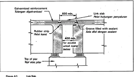
Where possible, the superstructure should be designed to be continuous or linked together at pier supports with a hinged linkage slab (normally as part
o
f the deck). An example of such a hinged slab, which causes negligible secondary bending moments, is shown in Figure A.3, from References A and B.Figure A.3 Link Slab
.3 ungan Sendi
A
t abutments, positive longitudinal restraint should beGambar A Pelat Hub
provided unless there is a minimum overlap distances between superstructure and substructure, as shown in Figure A.5. Positive lateral restraint should also be provided to prevent permanent relative displacement between the end of the bridge
A
.3
PERSYARATAN
PERENCANAAN UMUM
A.3.1
INTEGRITAS STRUKTURAL DAN
PERLENGKAPAN TERHADAP
SIMPANGAN
A.3.1.1
Hubungan Horisontal
Integritas struktural hanya dapat dipelihara bila simpangan yang berlebih dikendalikan untuk mencegah jatuhnya elemen bentang dari tumpuan. Hubungan longitudinal positip harus diadakan antara bagian-bagian bangunan atas yang berdekatan pada tumpuan dan sendi, dan antara bangunan atas dan tumpuan pada pilar. Hubungan-hubungan ini harus mampu menyalurkan gaya-gaya tarik maupun gayagaya tekan.
Bila mungkin, bangunan atas harus direncanakan sebagai menerus atau dihubungkan menjadi bersatu pada tumpuan pilar dengan suatu pelat hubungan sendi (umumnya sebagai bagian dari pelat lantai). Suatu contoh pelat hubungan sendi, yang menyebabkan momen lentur sekunder yang dapat diabaikan, diberikan dalam Gambar A.3, dari Pustaka
A dan B.
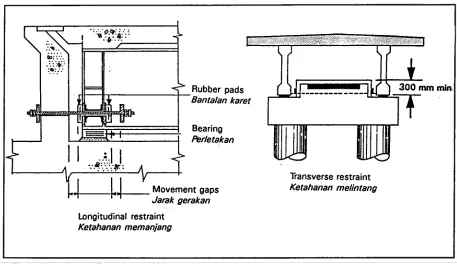
deck and the approaches. Lateral restraints shall have a minimum capacity as given in Subsection 2.9.
Some typical abutment restraint systems are shown in Figure A.4.
Figure A.4 Lateral Restraints at Abutments
Gambar A.4 Penahan Lateral pada Pangkal Jembatan
A.3.1.2
Holding-Down Devices
Holding-down devices should be provided at all bearings or supports to prevent vertical movements under seismic actions.
The minimum vertical seismic design load for such devices is given in clause 2.4.7.3. However, in continuous bridges this force may be exceeded and the design loading must be calculated. The vertical loading at supports of a continuous bridge is calculated on the assumption that the applied horizontal seismic force is large enough to cause all plastic hinges to develop their overstrength bending moments (clause A.2.5.3).
Holding-down devices should be designed to allow relative horizontal movement unless such movements are prevented by horizontal linkages.
Alternatively, a suitably designed ductile shear key with no hold down but with a 300 mm minimum upstand measured from the lowest point of lateral resistance on the deck superstructure may be used.
pendekatnya. Penahan lateral harus mempunyai suatu kapasitas minimum sesuai dengan Bab 2.9.
Berbagai tipikal sistim penahan pada pangkal diberikan dalam Gambar A.4.
A.3.1.2 Perlengkapan Penahan Vertikal
Perlengkapan penahan vertikal harus diadakan pada semua perletakan atau tumpuan untuk mencegah gerakan vertikal pada aksi seismik.
Rencana beban seismik vertikal minimum untuk perlengkapan tersebut diberikan dalam pasal 2.4.7.3. Bagaimanapun, pada jembatan menerus gaya tersebut dapat dilampaui dan pembebanan rencana harus dihitung. Pembebanan vertikal pada tumpuan jembatan menerus dihitung berdasarkan anggapan bahwa gaya seismik horisontal yang bekerja, adalah cukup besar untuk menyebabkan perkembangan momen kekuatan lentur lebih dalam semua sendi plastis (pasal A.2.5.3).
Perlengkapan penahan vertikal harus direncanakan agar mengijinkan gerakan horisontal relatip kecuali bila gerakan tersebut dicegah oleh hubungan horisontal.
A.3.1.3
Horizontal Clearance
Clearances between major structural elements and around holding-down devices may be calculated in accordance with clause A.2.10.2.
If the calculated displacements are unacceptably large, or if the calculations are uncertain due to the complexity or lack of ductility of the structure, it will be necessary to provide horizontal linkages designed in accordance with clause A.3.1.1.
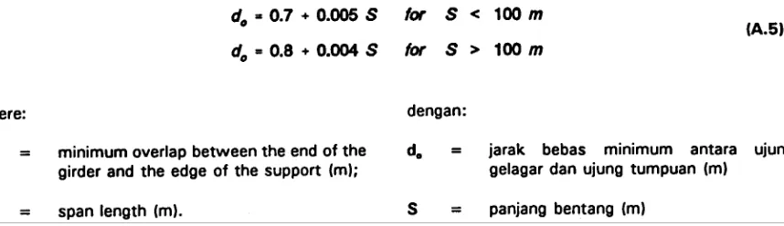
Where there are no provisions to limit relative movements at bearings or expansion joints (such as buffers and/or linkages), a minimum overlap between the end ofthe girder and the edgeofthe support (see Figure A.5) shall be provided as follows (Reference D):
Attention should also be given to the design of clearances around minor structural elements such as deck movement joints. Strong seismic motion can be expected to cause damage at such locations and the design Engineer should detail these elements so that permanent repairs can be carried out easily.
Figure A.5 Overlap Distance
Gambar A.5 Jarak Bebas
A.3.1.3
Jarak Bebas Horisontal
Jarak bebas antara elemen struktural utama dan sekitar perlengkapan penahan vertikal dapat diperhitungkan sesuai dengan pasal A.2.10.2.
Bila simpangan yang dihitung menjadi terlampau besar, atau bila perhitungan kurang meyakinkan akibat kerumitan atau kekurangan daktilitas struktur, maka diperlukan pengadaan hubungan horisontal yang direncanakan sesuai pasal A.3.1.1.
Dimana tidak terdapat perlengkapan untuk membatasi gerakan relatip pada perletakan atau hubungan dilatasi (seperti peredam dan/atau hubungan), suatu jarak bebas minimum antara ujung gelagar dan ujung tumpuan (lihat Gambar A.5) harus diadakan sebagai berikut (Pustaka D):
3.2
REPAIR CONSIDERATIONS
The Design Engineer should consider the likely method of repair and ease of access to areas of a structure where seismic damage will most probably occur. It is important to consider the hierarchy of inelastic failure of structural members during strong earthquake motions so that the members that will fail first are the easiest to repair.
Where the superstructure is supported on bearings, provision shall be made for jacking the superstructure so that the bearings can be removed and replaced. In this respect, the arrangement of anchorage bolts on the bearings shall be such that the bearings can be removed without requiring excessive jacking of the superstructure.
For the repair of plastic hinge areas on piers, it may be an advantage to provide suitable locating fixtures or holes in the piers for the support of scaffolding.
A.3.3
FREE STANDING RETAINING WALLS
A.3.3.1
General
Either of the following design methods may be used:
i. Design the wall to remain elastic (Type C) and not suffer any significant permanent displacement during the design earthquake. This will ensure a more serviceable structure than the following method (ii), but it may not be feasible or economic in all cases.
ii. Accept a limited amount of permanent outward movement of the wall and design for a mode failure which avoids yielding of structural elements wherever practicable. If outward movement of the walr cannot occur without yielding of structural elements, the cost of repairs may be unacceptable.
A.3.3.2
Static Earth Pressure
The static earth pressure on the wall should be computed in accordance with Sub-section 4.6. Care should be taken to determine if the static earth pressure is acting in a normal or relieving sense.
4.3.3.3
Inertial Force
The inertial force generated by the wall's self weight
A.3.2
PERTIMBANGAN PERBAIKAN
Ahli Tehnik Perencana harus mempertimbangan kemungkinan cara perbaikan dan kemudahan dalam mencapai bagian-bagian struktur dimana kerusakan seismik akan paling mungkin terjadi. Adalah penting untuk mempertimbangkan cara terjadinya keruntuhan tidak elastis dari komponen struktural pada gerakan gempa kuat sehingga komponen yang akan runtuh terlebih dahulu adalah yang paling mudah diperbaiki.
Bila bangunan atas ditumpu pada perletakan, harus diadakan tempat pendongkrakan bangunan atas sehingga perletakan dapat diambil dan diganti. Mengingat ini, penempatan baut angker pada perletakan harus sedemikian agar perletakan dapat diambil tanpa diperlukan pendongkrakan berlebih pada bangunan atas.
Untuk perbaikan daerah sendi plastis pada pilar, akan dapat menguntungkan bila disediakan profil tertanam atau lubang dilokasi sesuai dalam pilar untuk penempatan tumpuan dari penyangga.
A.3.3
TEMBOK PENAHAN YANG BERDIRI
BEBAS
A.3.3.1
Umum
Salah satu dari cara perencanaan berikut dapat digunakan:
i. Rencanakan tembok agar tetap elastis (Tipe C) dan tidak mengalami simpangan permanen yang berarti selama terjadi gempa rencana. Ini akan menjamin suatu kelayanan struktural lebih baik dari cara berikut (ii), tetapi hal ini mungkin kurang layak atau ekonomis dalam semua kasus.
ii. ljinkan gerakan permanen kearah luar tembok secara terbatas dan rencanakan untuk suatu keruntuhan perubahan bentuk/ragam yang mencegah pelelehan elemen struktural sedapat mungkin. Bila gerakan kearah luar tembok tidak dapat terjadi tanpa pelelehan elemen struktural, maka biaya perbaikan dapat menjadi terlalu besar.
A.3.3.2
Tekanan Tanah Statik
Tekanan tanah statik pada tembok harus dihitung sesuai dengan Bab 4.6. Harus dijaga agar ditentukan apakah tekanan tanah statik bekerja secara biasa atau mengurangi pengaruh.