Mobile User Interface Based on the Rear Touch Panel on Mobile
Device
Byung-Hun Oh
1,Jong-In Park
1and Kwang-Seok Hong
1 1 mobile devices is in demand. We propose mobile user interface based on rear touch panel on mobile device. In this paper, touch pad manufacture in the form of fixed or removable on the rear-facing of mobile device, there is provided a method of recognizing a control command(e.g., click, double click, drag and drop, moving) based on motion of a user’ s finger. For applying a set of previously defined commands, we are applied interface to application that produced by direct. The proposed algorithm will enable easier and more intuitive to control and operate the mobile device, can apply to application of various forms.Keywords: mobile user interface, touch panel, finger motion
1. Introduction
The rapid growth of mobile devices including smart-phones and tablet PCs has introduced multimedia content and web services to our lives. Users want to increase their interaction efficiency with mobile devices and applications. To support this demand, the importance of user interface (UIs) has increased. Mobile UIs comprise the interaction between a user and a mobile device. A user's ability to efficiently control the device is strongly related to the UI [1].
Currently mobile phones with a touch screen have been released. A touch screen contains the strength, such as an ease to control, an intuition, and a wide display. Now mobile phones with a touch screen are developing because of these advantages. Mobile phones with a touch screen are expected to account for 69.4% of the market by 2012. Moreover, mobile contents using the existing keypad need to be adjusted to the touch screen. This will cause a rise in the quality of the content, which had been restricted because of a limitation of the input device, as ,the existing keypad. This might be an opportunity to have sympathy for users who think it is difficult to control the keypad mobile contents [2].
Depending on the circumstances of use, sometimes it is desirable for a user of a mobile device to control the mobile device and the contents played on the mobile device with the use of one hand. The proposed system can support a user interface (UI) using only the index finger of the hand holding the mobile device [3].
double click, drag and drop, and moving operations using a touch input device on a back surface of a mobile terminal, thereby providing a convenient and efficient user interface.
2. System Configuration
2.1. System configuration
The overall configuration of the system is shown in Figure 1. MCU (Micro Control Unit) module using ATMEGA128 and TSC2004 touch pad, FB155 Bluetooth module and mobile device using the SPH-M84100 in SAMSUNG smartphone, is divided into three parts.
Figure 1. System configuration
2.1.1. MCU module: After storing coordinate values received from the TSC2004 touch pad module, the X and Y coordinates are transmitted to the Bluetooth module using an internal program (UART transmission) on the ATMEGA128.
2.1.2. Bluetooth module: An FB 155 Bluetooth module is used. After sending data through the Txd Rxd terminal, a serial communication program of the mobile device is connected. LEDs were used to enable intuitive confirmation of the communication status, connection status, and power status.
2.2. Production of system
2.2.1. Touch pad circuit board manufacturing: For system production, an ATMEGA128 board was used. A TWI module was connected to the LCD output and touch screen module, and calibration was performed for the x, y coordinate values of the touch screen panel and displayed on the LCD screen. The coordinate values were sent through UART communication, and converted into character-type values using the predefined xputn() function.
2.2.2. Bluetooth and mobile device interlocking: The data is transmitted with Bluetooth UART communication. A separate regulator was attached to match the 3-V voltage required for the Bluetooth module. The settings on the Bluetooth interface board were set for pairing with Bluetooth mobile devices.
3. Proposed interface
Propose an interface for the control and operation of mobile devices using a touch pad on the rear face of a mobile device. A touch user interface (TUI) is a computer-pointing technology based on the sense of touch (haptics) [7]. Figure 5 illustrates an example of a mobile device with a touch input device, and Figure 6 illustrates an example of using such a device.
3.1. System overview
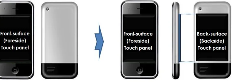
In Figure 4, an existing mobile device with touch input on its front surface is shown in comparison with a mobile device with touch input on its back surface.
Figure 4. An example of a mobile device with touch input
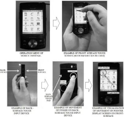
For example, a mobile device may include a front-surface touch panel as a touch input device that allows a user to use a stylus to manipulate the operation menu, which requires both hands, with one hand used to hold the mobile device, and the other hand to hold the stylus. In other examples, the touch input device may allow the user to touch the display screen to manipulate the operation menu. Another method of using the mobile device may include holding the mobile device with one hand with an index finger facing the back surface of the mobile device. The user may touch the touch input device provided on the back surface of the mobile device to move a pointer displayed on the display screen on the front surface of the mobile terminal. In this example, the mobile device allows the user to visualize the movement of the finger on the back surface of the mobile device by displaying a pointer on the front-surface display screen.
Figure 5. An example of a method of using a mobile device with a touch input device
3.2. Command definition
double click commands are triggered by one and two touches, respectively, similarly to the gesture of clicking a mouse. The control command corresponding to the length of time for which the pointer is touched to an object triggers the object selection command for dragging and dropping the object. The object selection command is triggered in response to the pointer being touched to an object for a time equal to or longer than a predetermined length. Moving action was defined to control the movement of a button or image using a momentary finger movement behavior of up, down, left or right on the touch pad.
3.3. Commands implementation
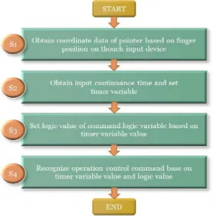
This proposed control method involves: (a) obtaining coordinate data of a pointer corresponding to the position of the finger in contact with a touch input device of a mobile terminal; (b) obtaining the input continuance time of the coordinate data, and setting values of timer variables based on the input continuance time; (c) setting logic values of several command logic variables whose logic values of True or False are based on values of the respective timer variables; and (d) recognizing an operation control command of the pointer based on the respective timer variable values and the command logic variable values.
Figure 6 is a block diagram of a mobile device example in which a method of recognizing a pointer control command based on finger motion is implemented. The mobile device includes a touch input device that is fixed or can be attached and detached from the mobile device, a controller, and storage. The method of recognizing a pointer control command based on finger motion is described below. In the mobile device, a pointer control command may be input through the touch input device installed on the back surface of the mobile device. Examples of devices that may be used as the touch input device include touch panels, touch pads, and similar devices. When display function is unnecessary on the back surface of the mobile device, a device that only recognizes a touch may be used as the touch input device. Further, the touch input device may be installed on other surfaces of the mobile terminal or provided as a detachable device.
Figure 6. An example of a block diagram of a mobile device in which a method of recognizing a pointer control command based on finger motion is
implemented
Figure 7. A flowchart illustrating an example of the overall process of the proposed finger motion command method
After the coordinate data is obtained, in step S2, the controller of the mobile device receives the input continuance time of the coordinate data received via the touch input device as one or more timer variables, and sets the values of timer variables. Then, the controller stores the timer variables. n this example, respective timer variables, Timer before (Tb), Timer after (Ta) and Timer middle (Tm) are variables for which a time value is input for storage. In this example, the values stored in times variables Tb, Ta, and Tm are each compared with a predefined time value, and an operation control command of the pointer is performed using the variables Tb, Ta, and Tm.
After performing step S2, in step S3, the controller sets several command logic variables
whose logic values of “True” or “False” are selected on the basis of the timer variables, and
stores the set command logic values in the storage. To this end, each of the timer variables Tb, Ta, and Tm includes a logic value field that is set to “True” when a time value is input,
and “False” when no time value is input. In this example, there are at least four command
logic variables: Click, D_Click, Drag, and Moving, the logic values of which correspond to a click operation, a double click operation, a drag operation, and a moving operation, respectively. The moving operation does not denote an operation of moving a specific object displayed on a display screen. Rather, the moving operation denotes the operation of moving the entire screen in a predetermined direction.
The controller is placed in a first state, a second state, a third state, and a fourth state according to the values of variables Tb, Ta, and Tm; whether or not pointer coordinate data is input; and the logic variable values of Click, D_Click, Drag, and Moving.
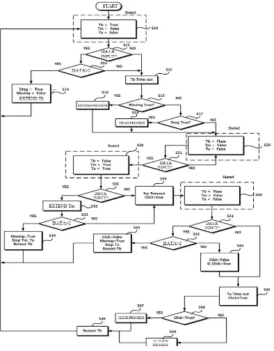
3.3.2. Commands Recognition Method: Figure 8 is a flowchart illustrating an example of a process by which step S4 of Figure 7 may be implemented.
In order for the controller to recognize an operation control command of the pointer on the basis of the respective timer variable values and the command logic variable values after step S3, in the first state, the logic value of Tb is set to “True” and logic values of Tm and Ta are
set to “False” in step S10. In this example, setting the value involves either assigning a
different value or maintaining the stored value, based on the value that is already stored in the variable. However, in another example, a new value may be assigned to the variable without checking whether the variable already contains the same value.
After step S10, if coordinate data of the pointer is not input to the touch input device within a time that has been defined as Tb in advance (S11 and S12), the controller proceeds to the second state (S20). For example, when coordinate data of the pointer is not received within the time that has been set as Tb in advance, the logic values of Moving and Drag are set to
“False,” and the controller proceeds to the second state.
If the logic value of Moving has been set to “True” when input of the time value of Tb is
completed, the controller recognizes operation control of the pointer as Moving and proceeds to the second state, as illustrated in step S16.
More specifically, if the logic value of Moving has been set to “False” in step S15, and the logic value of Drag has been set to “True” in step S17, when the input of the time value of Tb
is completed in step S12, the controller 12 recognizes operation control of the pointer as Drag as in step S18 and proceeds to the second state in S20.
When two or more pieces of coordinate data of the pointer are input within the time that has been defined as Tb in advance (S11 and S13), the controller 12 sets the logic value of
Drag to “True” and the logic value of Moving to “False” (S14). Also, the controller extends
the time value that has been set as Tb in advance.
The controller causes the second state to start with logic values of Tb, Tm and Ta set to
“False” (S20), and maintains the second state when no coordinate data of the pointer is input
to the touch input device (S21).
For example, the controller proceeds to the third state (S30) when coordinate data of the pointer is input to the touch input device (S21), and maintains the second state when no coordinate data of the pointer is input to the touch input device (S21).
The controller causes the third state to start with a logic value of Tb set to “False” and
logic values of Tm and Ta set to “True” (S30). When no coordinate data of the pointer is input to the touch input device (S31) or only one piece of coordinate data of the pointer is input within a time that has been defined as Tm in advance (S33), the controller may set the logic value of Click as “True” (S35) and proceeds to the fourth state (S40). In this example, even when only one piece of coordinate data of the pointer is input in step S31, the controller extends the time value that has been set as Tm in advance (S32).
When two or more pieces of coordinate data of the pointer are input to the touch input device within the time value that has been defined as Tm in advance in step S33, the
controller sets the logic value of Moving to “True” as in step S34 and proceeds to the first
state as in step S10. In step S34, the controller stops changing the time values that have been defined as Tm and Ta in advance, resets the time value that has been defined as Tb in advance, and then proceeds to the first state.
The controller initiates the fourth state with the logic values of Tb and Tm set to “False”
and the logic value of Ta set to “True” (S40). When two or more pieces of coordinate data of
the pointer are input to the touch input device (S42), the controller sets the logic value of
Click to “False” and the logic value of Moving to “True,” (S43) and proceeds to the first state
When two or more pieces of coordinate data of the pointer are not input to the touch input device (S42) after the controller causes the fourth state to start with the logic values of Tb and
Tm set to “False” and the logic value of Ta set to “True” (S40), the controller sets the logic value of Click to “False” and the logic value of D_Click to “True” (S44).
After step S44, if the logic value of Click has been set to “True” when the time value that
has been defined as Ta in advance elapses (S45), the controller recognizes operation control of the pointer input to the touch input device 11 as a Click (S47). Here, when the logic value
of Click has been set to “False,” the controller recognizes the operation control of the pointer
as D_Click (S49) and proceeds to the first state (S10).
After step S47 and step S49, the controller resets the time value that has been set as Tb in advance (S48), and then proceeds to the first state.
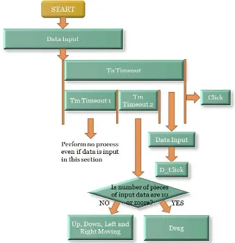
Figure 9 is a diagram illustrating an example of the process of setting logic values of command logic variables corresponding to Click, D_Click, Moving, and Drag in step S3 of Figure 7. The controller sets a logic value of a command logic variable corresponding to Click when a time that has been set as Ta in advance elapses (S200) after data input (S100).
Figure 9. diagram illustrating an example of a process of setting logic values of command logic variables in accordance with step S3 of Figure 7
When, for example, 10 or more pieces of data are input during the duration of a second time period (Timeout 2) that has been set as Tm in advance, the controller sets the logic value of the command logic variable corresponding to Drag. Alternatively, when less than 10 pieces of data are input, the controller sets the logic values of the command logic variables corresponding to moving up, down, left, and right.
Finally, when data is received during the time that has been set as Ta in advance and the second time that has been set as Tm in advance, the controller sets the logic value of the command logic variable corresponding to D_Click.
As described above, the proposed method may provide a set of commands for click, double click, drag and drop, and moving operations using a touch input device on the back surface of a mobile device, thereby providing a convenient and efficient user interface.
4. System Operation and Application
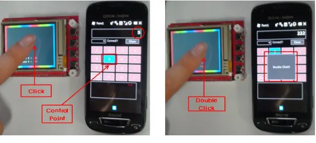
We implemented a few application to demonstrate the mobile interface using touch pad on the rear-facing. An example of control of click, double click and moving action is shown in Figure 10, Figure 11. The calculator applications run, after the port setting and connection, calculator was controlled by a set of commands for click, double click, drag and drop, and moving operations using a touch input device. Such a touch input device may also to be used with a front-surface touch input device such that the mobile terminal can be operated and controlled with both hands or with only one hand.
Figure 10. An example of control of click and double click
Figure 11. An example of control of moving action
content, etc. by continuously sensing motion of a user’s finger in contact with, or placed on, a
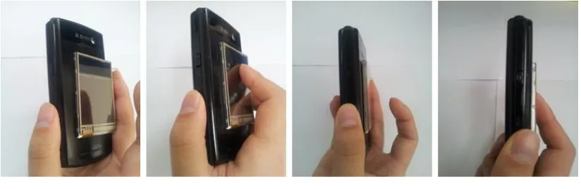
touch panel attached to a back surface, visually transferring a movement path of a touch point on a front surface. The method may allow recognizing click, double click, moving, and drag operations based on finger motion to allow a user to select a content of interest or an operation menu. Figure 12 shows the finished system and an example of applied system.
Figure 12. An example of applied system
5. Conclusion
In this paper, we propose mobile user interface based on rear touch panel on mobile device. The touch pad manufacture in the form of fixed or removable on the rear-facing of mobile device, there is provided a method of recognizing a control command(e.g., click,
double click, drag and drop, moving) based on motion of a user’s finger. For applying a set of
previously defined commands, we are applied interface to application that produced by direct. The proposed system further estimates the finger movement and operates the calculator applications through the rear-facing touch pad. As a result, this indicates the feasibility of the proposed algorithm for finger movement-based mobile user interfaces.
Acknowledgements
This work was supported by Priority Research Centers Program through the National Research Foundation of Korea(NRF) funded by the Ministry of Education, Science and Technology(2012-0005861) and Basic Science Research Program through the National Research Foundation of Korea(NRF) funded by the Ministry of Education, Science and Technology(2010-0021411) and by MKE, Korea under ITRC NIPA-2012-(H0301-12-3001).
References
[1] A. Mulder, "Hand gestures for HCI", Technical Report 96-1, Simon Fraster University, (1996).
Authors
Byung-Hun Oh received his B.S. degree in electronic engineering from the Eulji University, Seongnam, Korea, in 2011, M.S. degree in at the College of Information and Communication Engineering at Sungkyunkwan University, Suwon, Korea, respectively. He is presently a Ph.D. candidate at the College of Information and Communication Engineering at Sungkyunkwan University, Suwon, Korea. His current research focuses on digital image processing and pattern recognition.
Jong-In Park received his B.S. degree in electronic engineering from the Kwangwoon University, Seoul, Korea, in 2011. He is presently an M.S candidate at the College of Information and Communication Engineering at Sungkyunkwan University, Suwon, Korea. His current research focuses on digital image processing and pattern recognition.